AzureWave Technologies NM230NF IEEE 802.11 b/g/n Wireless LAN and Bluetooth combo M.2 1216 module User Manual AW AH691A
AzureWave Technologies, Inc. IEEE 802.11 b/g/n Wireless LAN and Bluetooth combo M.2 1216 module AW AH691A
Contents
- 1. Users Manual-1
- 2. Users Manual-2
- 3. User manual
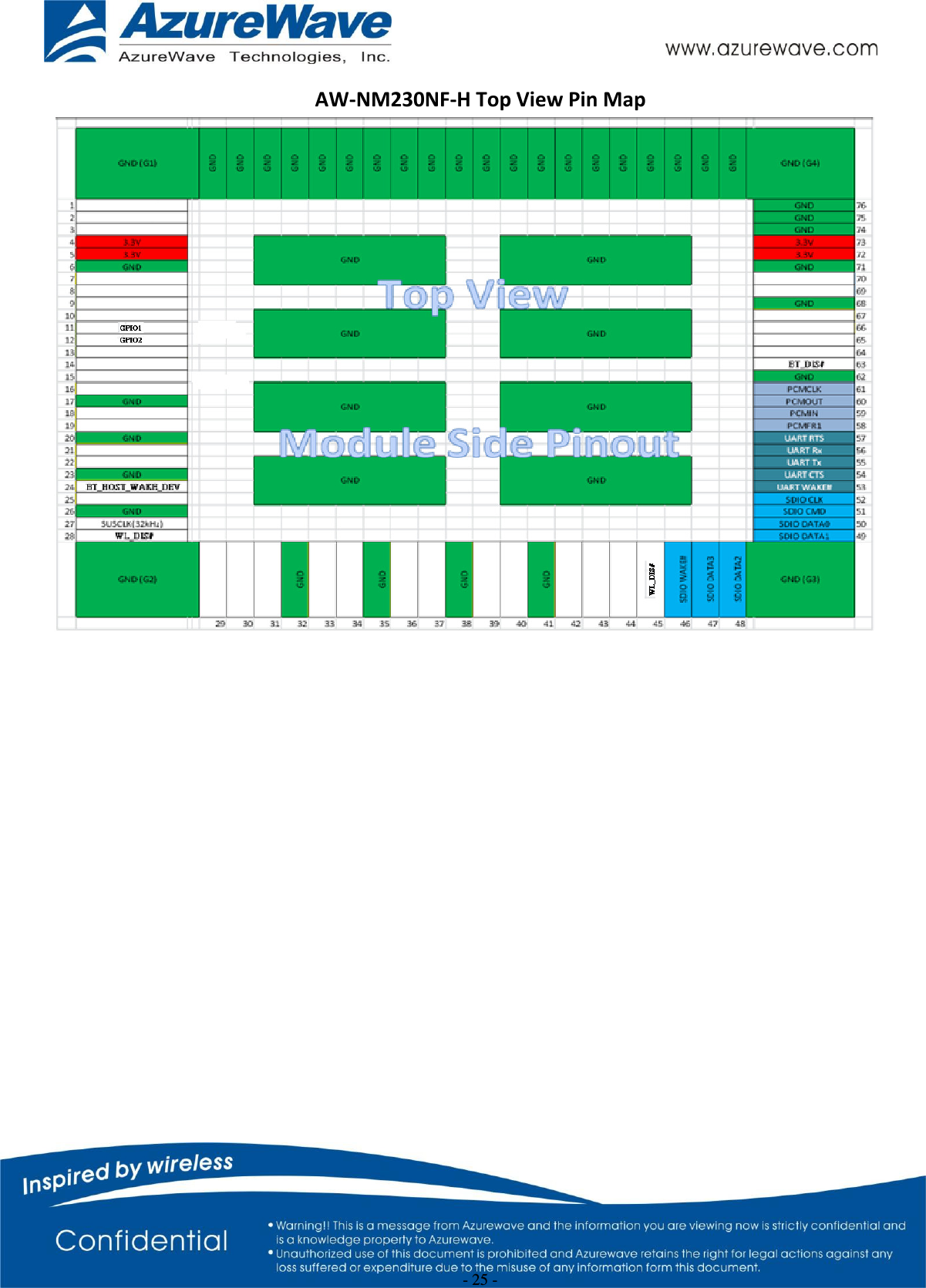
- 4. User manual statement
Users Manual-1
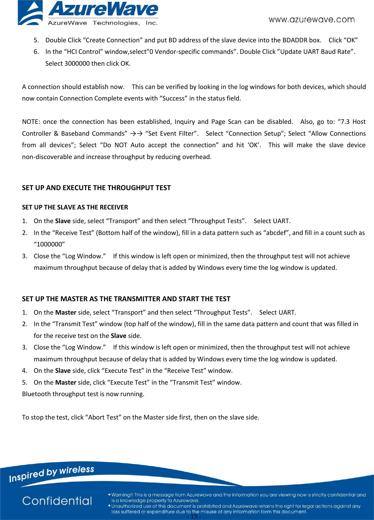
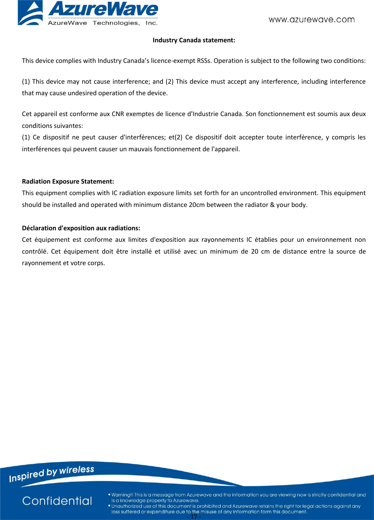
![- 2 - 1. WLAN Basic Test **Must connect USB to PC Driver Installation DRIVER INSTALLATION (IN LINUX) •First prepare the Broadcom’s linux package, and put it in the “home”folder. •Open the Terminal, enter the command: sudo su and password. •Enter cd /home/username/drivername/src/dhd/linux •Enter make dhd-cdc-sdmmc-gpl to generate the dhd.ko file in /home/username/ drivername /src/dhd/linux/dhd-cdc-sdmmc-gpl-kernelversion •Enter Insmod /(path of dhd.ko file) firmware_path=/(path of firmware file) nvram_path=/(path of nvram file) to enable. •Enter rmmod dhd to disable Throughput Test CONNECTING TO WIRELESS NETWORKS The examples in the following sections illustrate how to connect to both infrastructure and ad hoc networks, including infrastructure networks that use no security, WEP security, and WPA/PSK and WPS2/PSK security. SCANNING FOR WIRELESS NETWORKS To force the dongle to scan • Run wl scan. To force the dongle to return the results of the scan • Run wl scanresults. Example results returned when an AP is found: • SSID: “Eval4325” • Mode: Managed: RSSI: -48 dBm noise: -105 dBm Channel: 1 • BSSID: 00:10:18:90:2E:C1 Capability: ESS ShortSlot • Supported Rates: [ 1(b) 2(b) 5.5(b) 11(b) 18 24 36 54 6 9 12 48 ] Example results returned when an ad hoc network is found: • SSID: “ADHOC#1” • Mode: Ad Hoc RSSI: -41 dBm noise: -105 dBm Channel: 1](https://usermanual.wiki/AzureWave-Technologies/NM230NF.Users-Manual-1/User-Guide-2707136-Page-2.png)
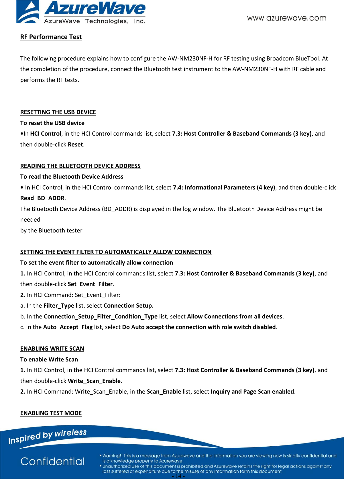
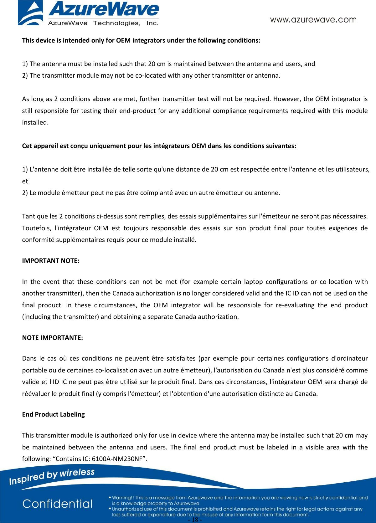
![- 3 - • BSSID: B2:51:28:6B:3C:A1 Capability: IBSS • Supported Rates: [ 1(b) 2(b) 5.5(b) 11(b) ] CONNECTING TO AN INFRASTRUCTURE NETWORK WITH NO SECURITY (AP CONNECTION) To connect to the network through an AP with SSID = Eval4325 Run wl join Eval4325. CONNECTING TO AN INFRASTRUCTURE NETWORK WITH WEP SECURITY To connect to the network that uses 12345 as the network key • Run wl join Eval4325 key 12345. CONNECTING TO AN INFRASTRUCTURE NETWORK WITH WPA-PSK/WPA2-PSK SECURITY To specify TKIP or AES as the data encryption method • Run wl wsec 3/7. To enable the supplicant • Run wl sup_wpa 1. To specify the PSK passphrase (network key) to use • Run wl set_psk $passphrase. To connect to a network that uses WPA-PSK security • Run wl join Eval4325 imode bss amode wpapsk. To connect to a network that uses WPA2-PSK security • Run wl join Eval4325 imode bss amode wpa2psk. CONNECTING TO AN AD HOC NETWORK USING CHANNEL 1 To set the channel to channel 1 • Run wl channel 1. To connect to the ad hoc network with SSID = 4325-ADHOC • Run wl join 4325-ADHOC imode ibss. MANAGING POWER CONSUMPTION To disable Power Save (PS) mode (default) • Run wl PM 0. To enable legacy IEEE 802.11 Power Save (PS) mode • Run wl PM 1. To enable Fast IEEE 802.11 Power Save mode • Run wl PM 2.](https://usermanual.wiki/AzureWave-Technologies/NM230NF.Users-Manual-1/User-Guide-2707136-Page-3.png)
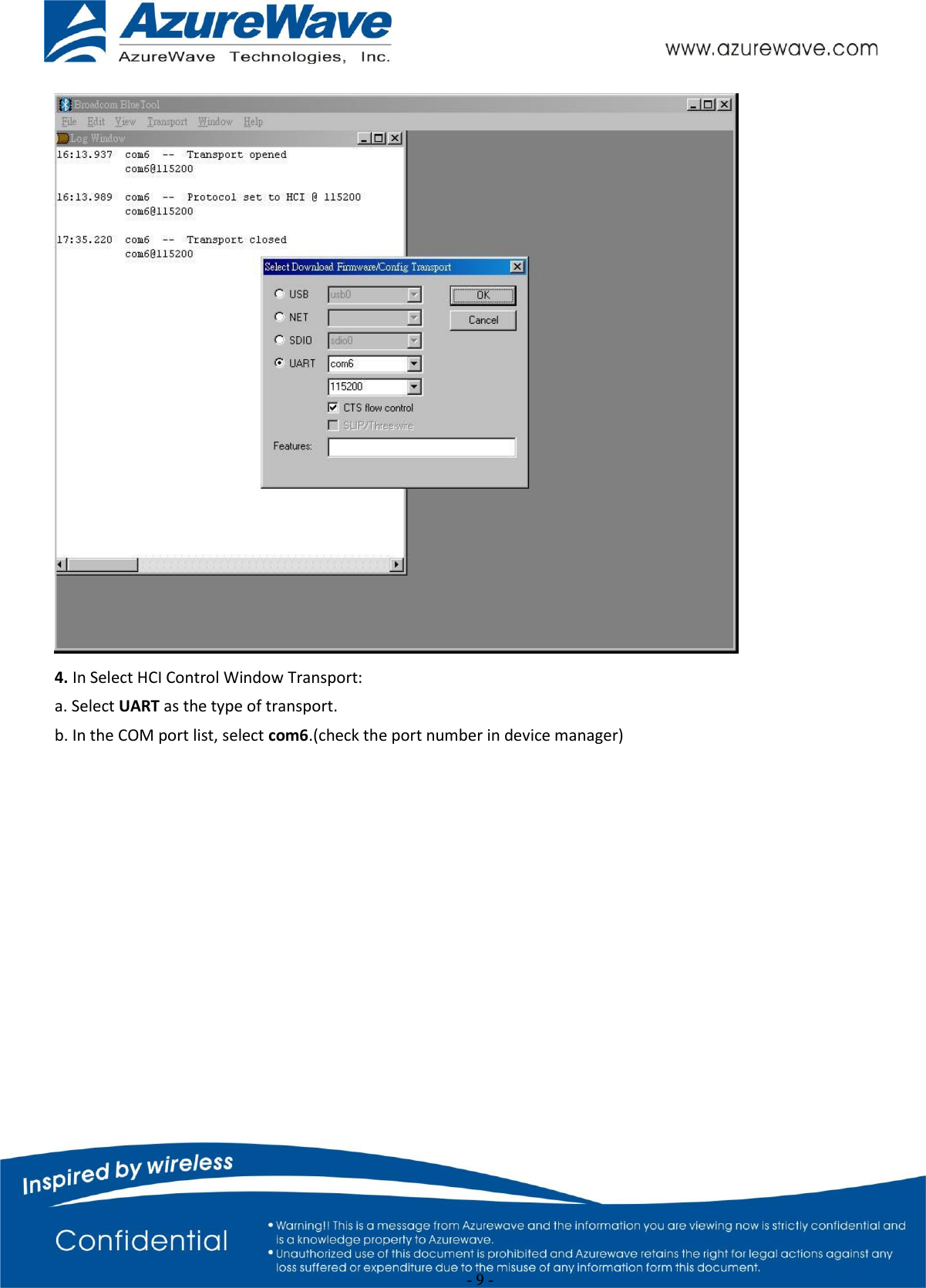
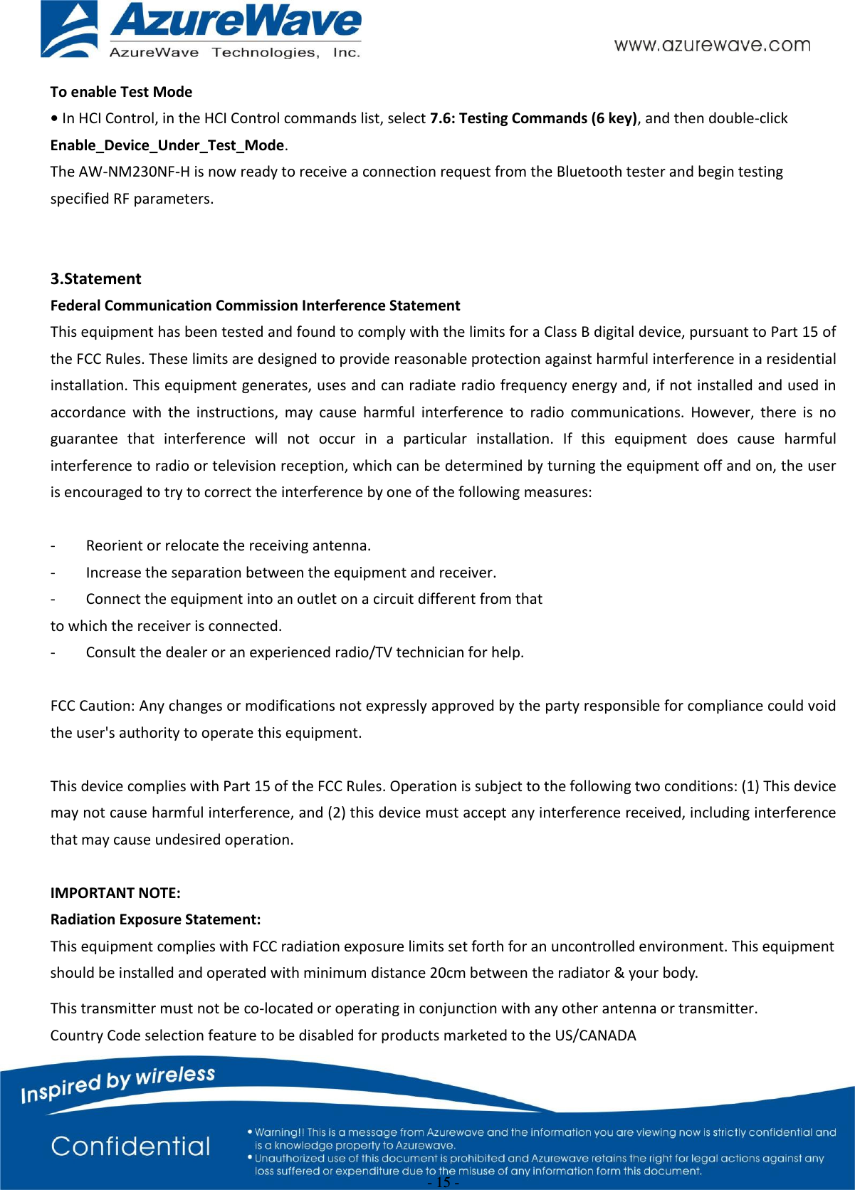
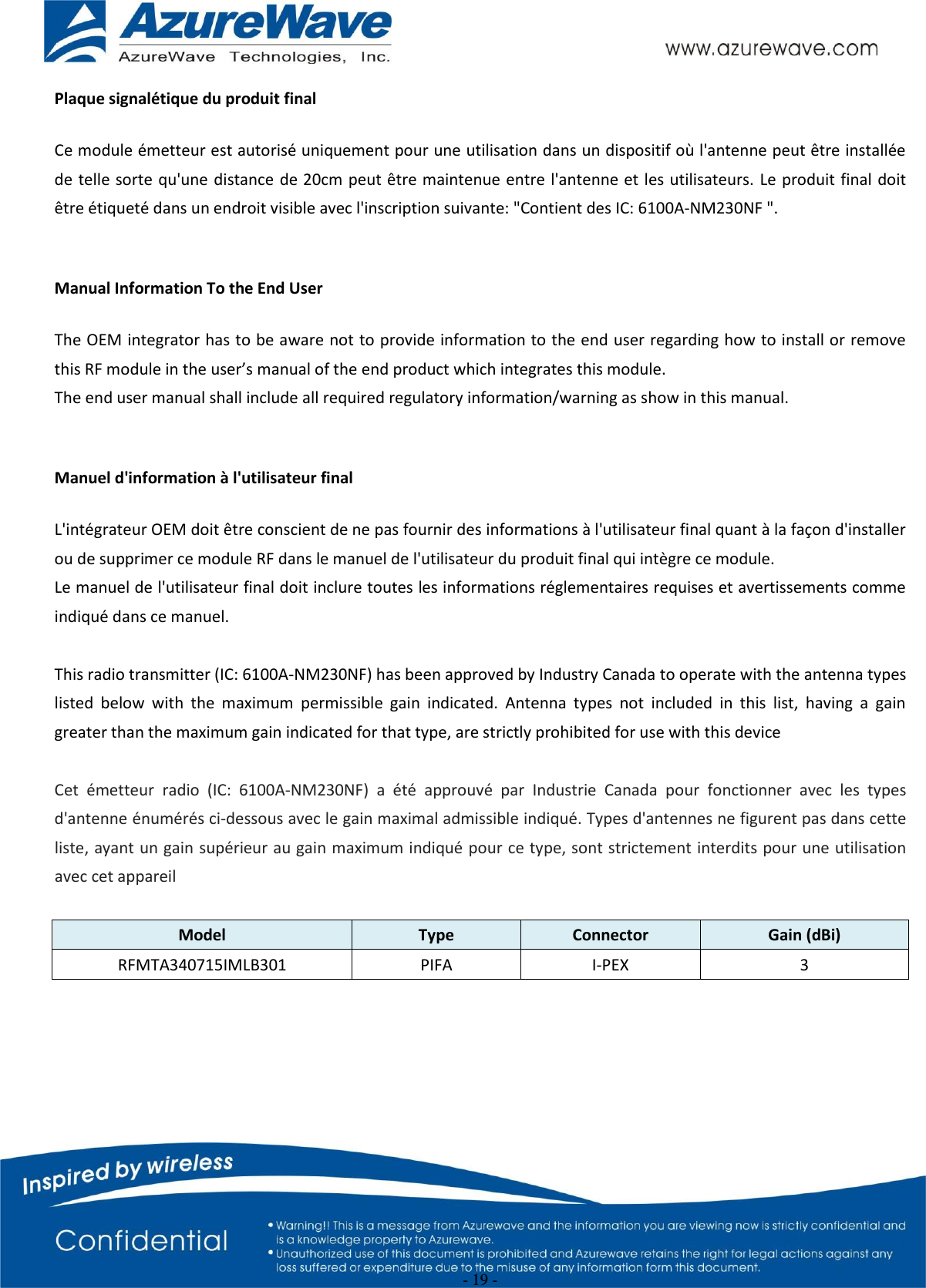
![- 8 - ./wl phy_forcecal 1 ./wl scansuppress 1 ./wl rxchain 1 ./wl reset_cnts ./wl counters This will enter Channel 7 receive mode. ※.The default MAC address is 001122334455. Packets sent from Signal Generator must have the same MAC address as the DUT’s MAC address (Runtime mac address can be overrode by using wl cur_etheraddr xx:xx:xx:xx:xx:xx . ※. Use “./wl counters” and find the received frame numbers in “rxdfrmocast”. ※. The RX PER = [ (Total lost packets at the receiver) / (Total sent packets from the Signal Generator) ] x 100%. Thus, PER =100% - [(rxdfrmocast numbers after sequence play) – (rxdfrmocast numbers before sequence play)] / (Total sent packets from the signal Generator) x 100%. . 2. Bluetooth Basic Test *Must connect USB to PC Download Mini-driver 1. Start Broadcom BlueTool. 2. On the View menu, click Log Windows Details. 3. On the Transport menu, click HCI Control.](https://usermanual.wiki/AzureWave-Technologies/NM230NF.Users-Manual-1/User-Guide-2707136-Page-8.png)