Avaya AP8120 802.11abgn Access Point User Manual NN47251 109 01 02 REGAP8120E

Avaya, Inc. 802.11abgn Access Point NN47251 109 01 02 REGAP8120E

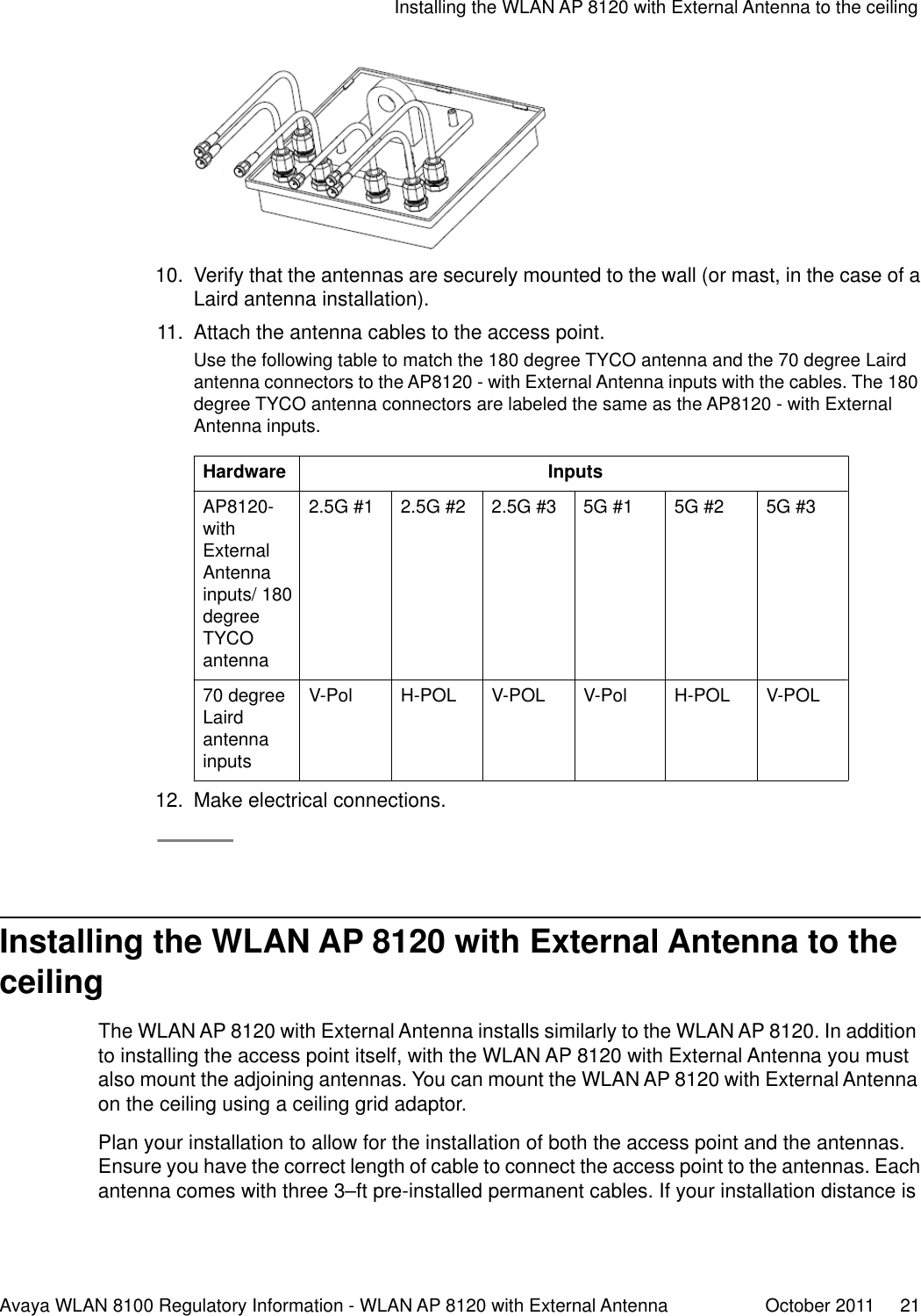
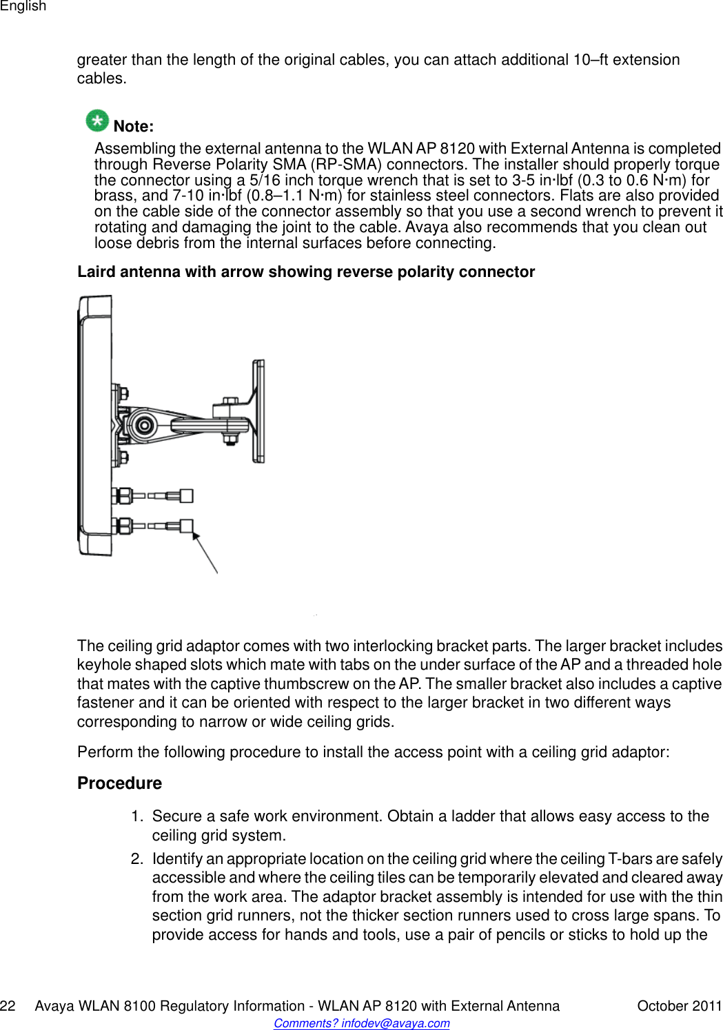
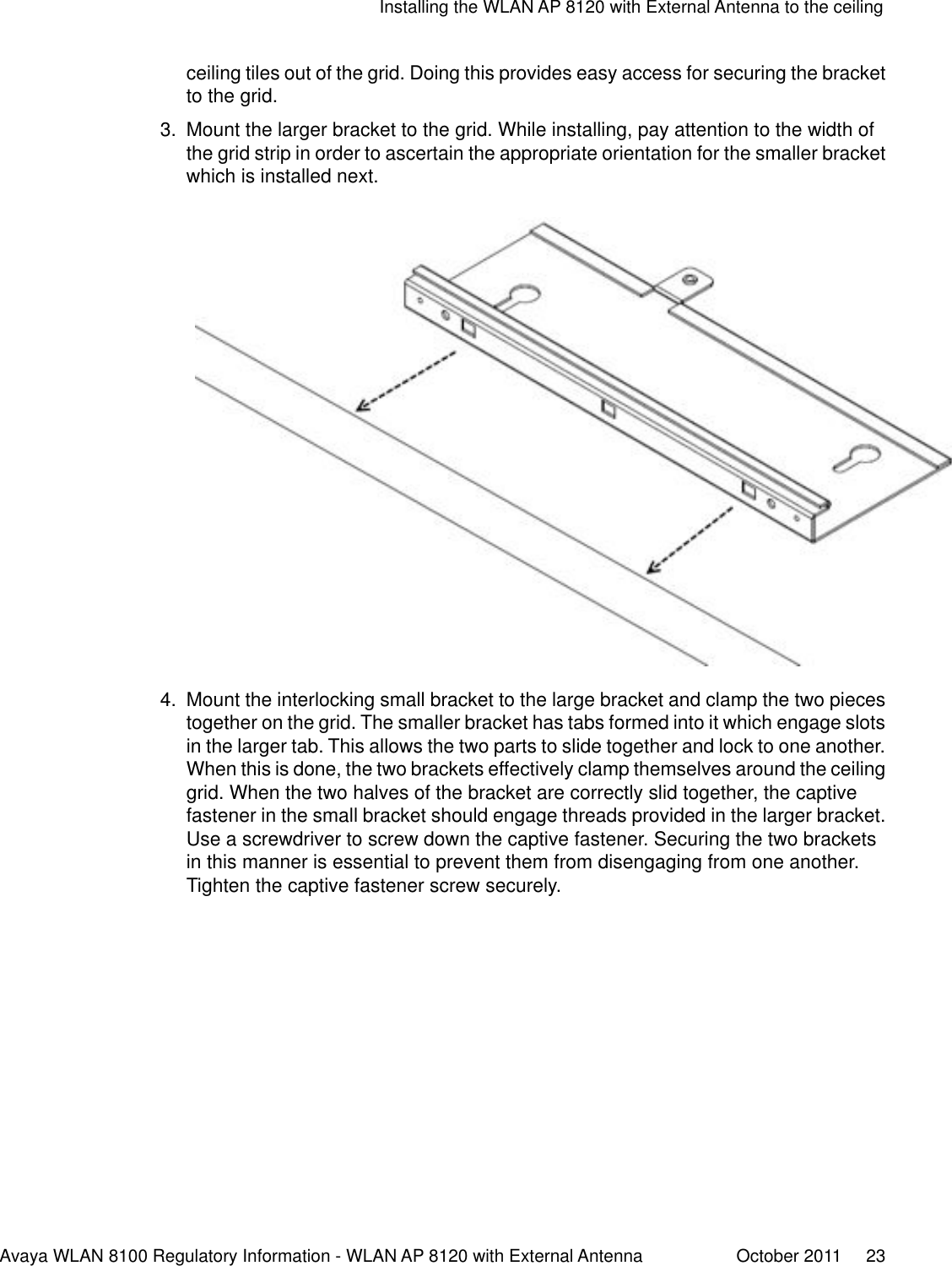
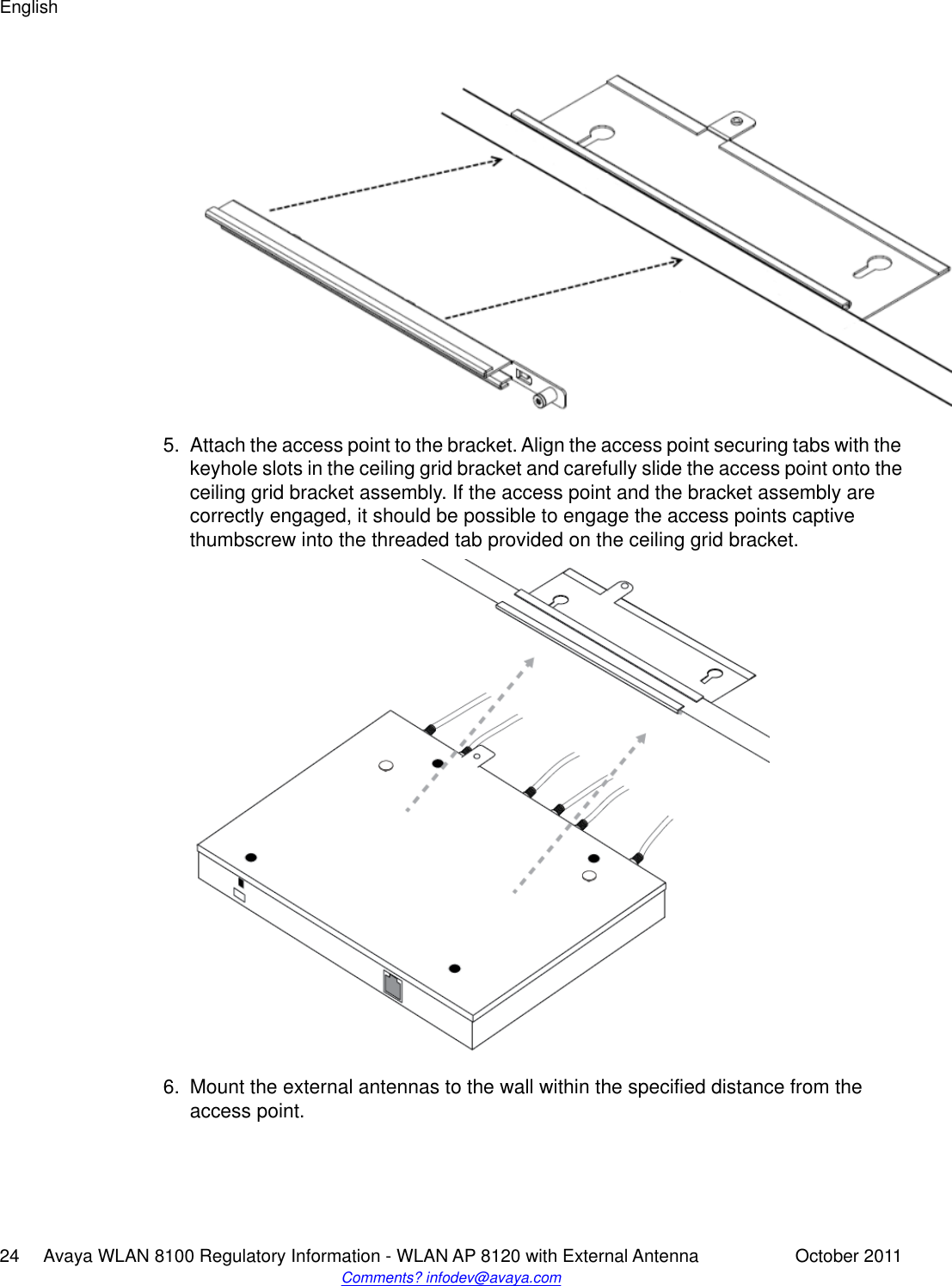
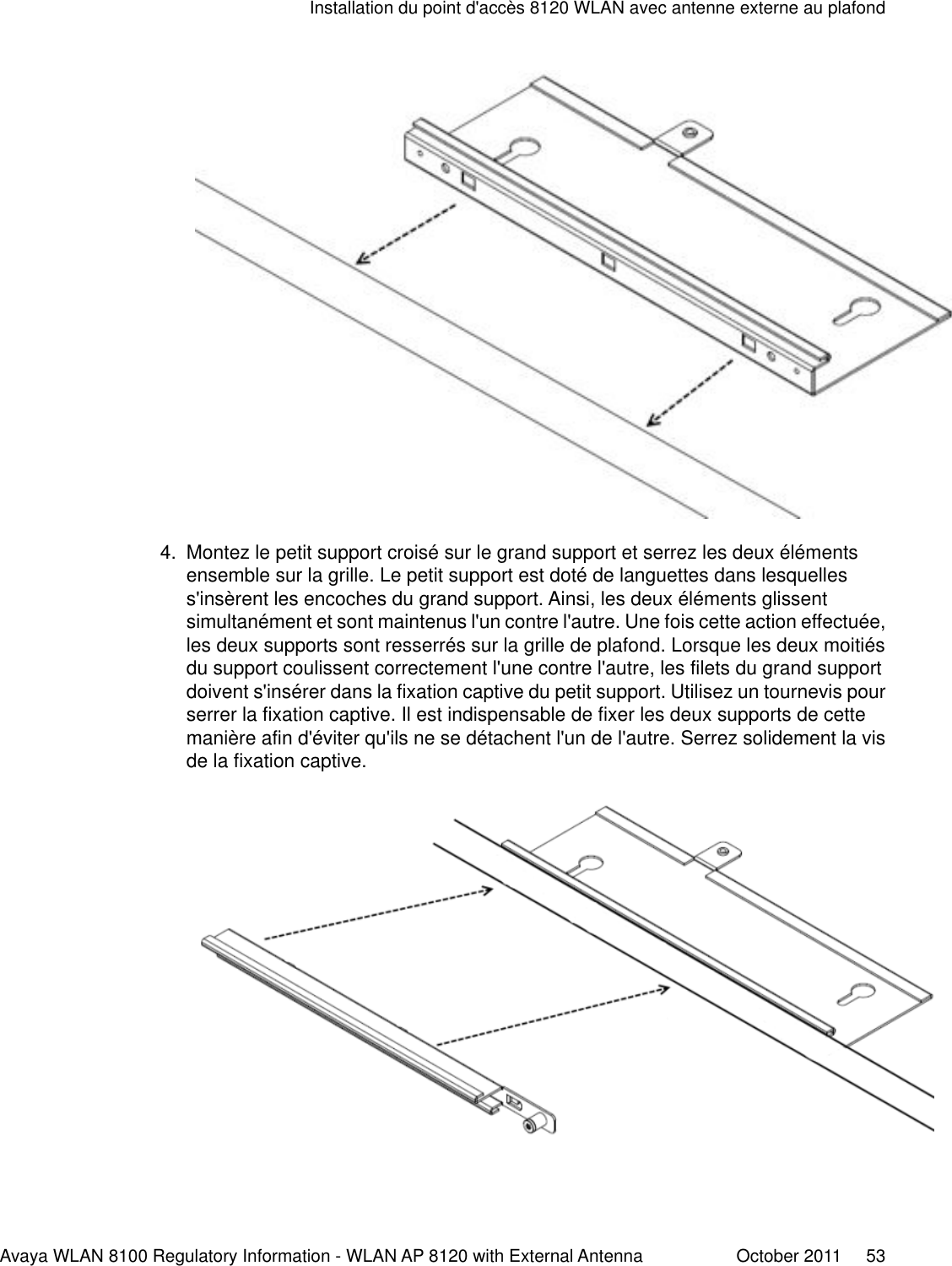
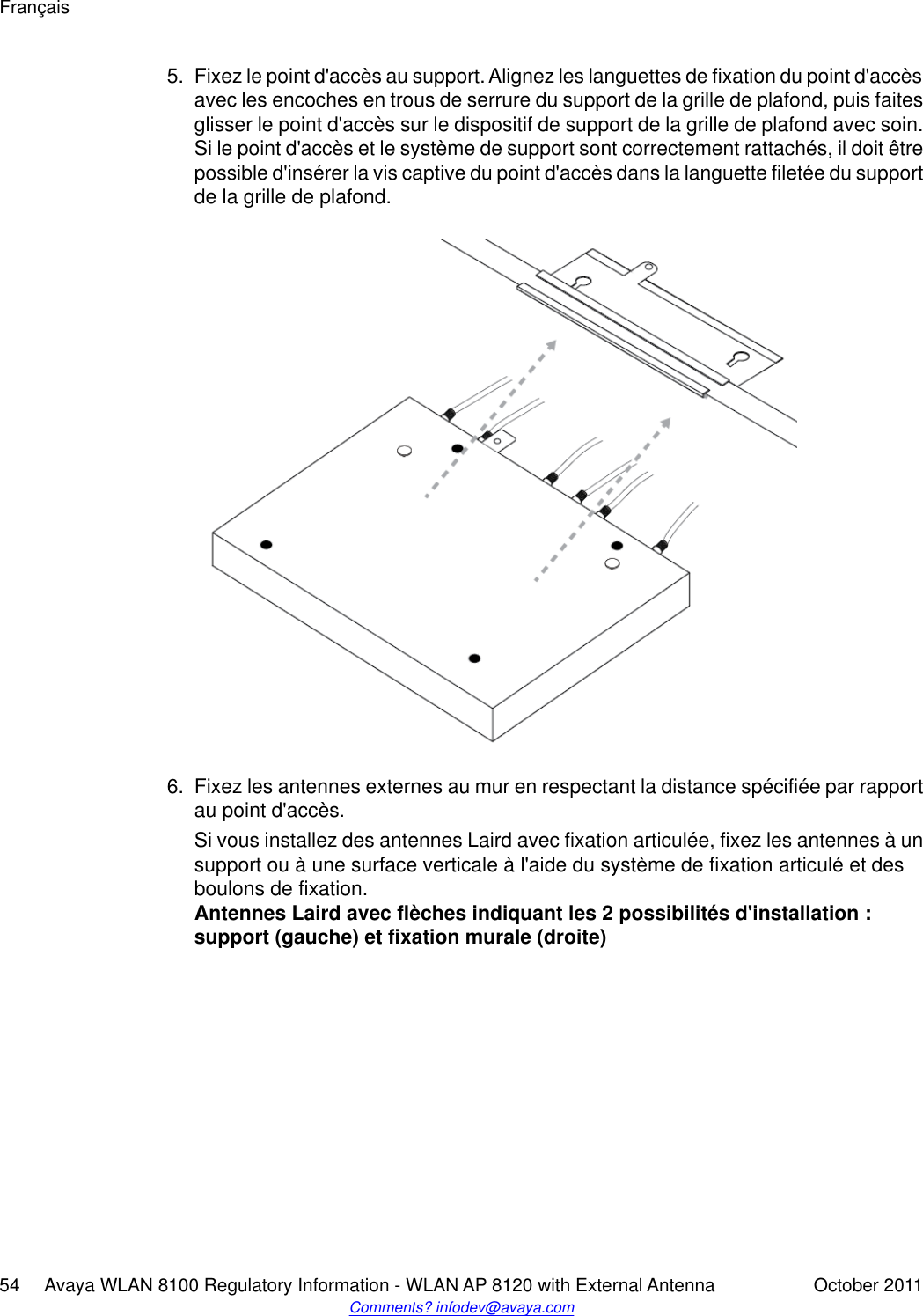
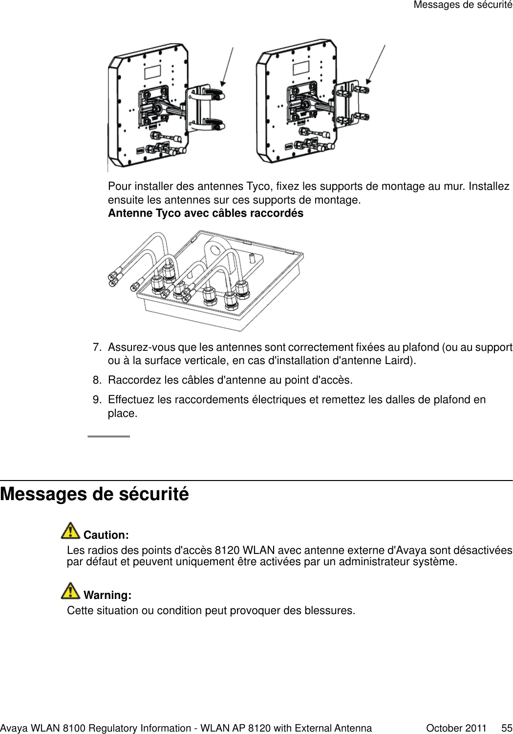
NN47251-109 01.02 REGAP8120E

Avaya WLAN 8100 Regulatory Information- WLAN AP 8120 with External Antenna1.1.0.0NN47251-109, 01.02October 2011
© 2011 Avaya Inc.All Rights Reserved.NoticeWhile reasonable efforts have been made to ensure that theinformation in this document is complete and accurate at the time ofprinting, Avaya assumes no liability for any errors. Avaya reserves theright to make changes and corrections to the information in thisdocument without the obligation to notify any person or organization ofsuch changes.Documentation disclaimer“Documentation” means information published by Avaya in varyingmediums which may include product information, operating instructionsand performance specifications that Avaya generally makes availableto users of its products. Documentation does not include marketingmaterials. Avaya shall not be responsible for any modifications,additions, or deletions to the original published version ofdocumentation unless such modifications, additions, or deletions wereperformed by Avaya. End User agrees to indemnify and hold harmlessAvaya, Avaya's agents, servants and employees against all claims,lawsuits, demands and judgments arising out of, or in connection with,subsequent modifications, additions or deletions to this documentation,to the extent made by End User.Link disclaimerAvaya is not responsible for the contents or reliability of any linked Websites referenced within this site or documentation provided by Avaya.Avaya is not responsible for the accuracy of any information, statementor content provided on these sites and does not necessarily endorsethe products, services, or information described or offered within them.Avaya does not guarantee that these links will work all the time and hasno control over the availability of the linked pages.WarrantyAvaya provides a limited warranty on its Hardware and Software(“Product(s)”). Refer to your sales agreement to establish the terms ofthe limited warranty. In addition, Avaya’s standard warranty language,as well as information regarding support for this Product while underwarranty is available to Avaya customers and other parties through theAvaya Support Web site: http://support.avaya.com. Please note that ifyou acquired the Product(s) from an authorized Avaya reseller outsideof the United States and Canada, the warranty is provided to you bysaid Avaya reseller and not by Avaya.LicensesTHE SOFTWARE LICENSE TERMS AVAILABLE ON THE AVAYAWEBSITE, HTTP://SUPPORT.AVAYA.COM/LICENSEINFO/ AREAPPLICABLE TO ANYONE WHO DOWNLOADS, USES AND/ORINSTALLS AVAYA SOFTWARE, PURCHASED FROM AVAYA INC.,ANY AVAYA AFFILIATE, OR AN AUTHORIZED AVAYA RESELLER(AS APPLICABLE) UNDER A COMMERCIAL AGREEMENT WITHAVAYA OR AN AUTHORIZED AVAYA RESELLER. UNLESSOTHERWISE AGREED TO BY AVAYA IN WRITING, AVAYA DOESNOT EXTEND THIS LICENSE IF THE SOFTWARE WAS OBTAINEDFROM ANYONE OTHER THAN AVAYA, AN AVAYA AFFILIATE OR ANAVAYA AUTHORIZED RESELLER; AVAYA RESERVES THE RIGHTTO TAKE LEGAL ACTION AGAINST YOU AND ANYONE ELSEUSING OR SELLING THE SOFTWARE WITHOUT A LICENSE. BYINSTALLING, DOWNLOADING OR USING THE SOFTWARE, ORAUTHORIZING OTHERS TO DO SO, YOU, ON BEHALF OFYOURSELF AND THE ENTITY FOR WHOM YOU ARE INSTALLING,DOWNLOADING OR USING THE SOFTWARE (HEREINAFTERREFERRED TO INTERCHANGEABLY AS “YOU” AND “END USER”),AGREE TO THESE TERMS AND CONDITIONS AND CREATE ABINDING CONTRACT BETWEEN YOU AND AVAYA INC. OR THEAPPLICABLE AVAYA AFFILIATE ( “AVAYA”).CopyrightExcept where expressly stated otherwise, no use should be made ofmaterials on this site, the Documentation, Software, or Hardwareprovided by Avaya. All content on this site, the documentation and theProduct provided by Avaya including the selection, arrangement anddesign of the content is owned either by Avaya or its licensors and isprotected by copyright and other intellectual property laws including thesui generis rights relating to the protection of databases. You may notmodify, copy, reproduce, republish, upload, post, transmit or distributein any way any content, in whole or in part, including any code andsoftware unless expressly authorized by Avaya. Unauthorizedreproduction, transmission, dissemination, storage, and or use withoutthe express written consent of Avaya can be a criminal, as well as acivil offense under the applicable law.Third-party componentsCertain software programs or portions thereof included in the Productmay contain software distributed under third party agreements (“ThirdParty Components”), which may contain terms that expand or limitrights to use certain portions of the Product (“Third Party Terms”).Information regarding distributed Linux OS source code (for thoseProducts that have distributed the Linux OS source code), andidentifying the copyright holders of the Third Party Components and theThird Party Terms that apply to them is available on the Avaya SupportWeb site: http://support.avaya.com/Copyright.TrademarksThe trademarks, logos and service marks (“Marks”) displayed in thissite, the Documentation and Product(s) provided by Avaya are theregistered or unregistered Marks of Avaya, its affiliates, or other thirdparties. Users are not permitted to use such Marks without prior writtenconsent from Avaya or such third party which may own the Mark.Nothing contained in this site, the Documentation and Product(s)should be construed as granting, by implication, estoppel, or otherwise,any license or right in and to the Marks without the express writtenpermission of Avaya or the applicable third party.Avaya is a registered trademark of Avaya Inc.All non-Avaya trademarks are the property of their respective owners,and “Linux” is a registered trademark of Linus Torvalds.Downloading DocumentationFor the most current versions of Documentation, see the AvayaSupport Web site: http://support.avaya.com.Contact Avaya SupportAvaya provides a telephone number for you to use to report problemsor to ask questions about your Product. The support telephone numberis 1-800-242-2121 in the United States. For additional supporttelephone numbers, see the Avaya Web site: http://support.avaya.com.2     Avaya WLAN 8100 Regulatory Information - WLAN AP 8120 with External Antenna October 2011Comments? infodev@avaya.com
ContentsChapter 1: Regulatory Compliance Statements............................................................... 5Federal Communications Commission (FCC) Compliance Notices.......................................................... 5Class B Interference Statement................................................................................................................ 5Class B Equipment (Residential Use) (Korean)........................................................................................ 6FCC Caution............................................................................................................................................. 6RF Radiation Exposure and Hazard Statement........................................................................................ 6Non-Modification Statement...................................................................................................................... 7Deployment Statement.............................................................................................................................. 7Dynamic Frequency Selection (DFS) in the 5.0 GHz UNII bands............................................................. 7Canadian IC Statements........................................................................................................................... 7European Union and European Free Trade Association (EFTA) Regulatory Compliance........................ 8Declaration of Conformity.......................................................................................................................... 8European Community Declaration of Conformity...................................................................................... 9Countries of Operation and Restrictions of Use in the European Community.......................................... 11Operation Using the 2.400 to 2.4835 GHz Channels in the European Community.................................. 11Operation Using the 5.15 to 5.25 GHz, 5.25 to 5.35 GHz, and 5.470 to 5.725 GHz Channels in theEuropean Community............................................................................................................................... 12Dynamic Frequency Selection (DFS)........................................................................................................ 12Transmit Power Control............................................................................................................................ 13Antenna Statement................................................................................................................................... 13Chapter 2: Devices with detachable antennas................................................................. 15Chapter 3: English.............................................................................................................. 17Cable requirements................................................................................................................................... 17Mounting the WLAN AP 8120 with External Antenna on a wall................................................................ 17Installing the WLAN AP 8120 with External Antenna to the ceiling.......................................................... 21Safety Messages....................................................................................................................................... 26Chapter 4: Deutsch............................................................................................................. 27Kabelanschlüsse....................................................................................................................................... 27Wandmontage des WLAN AP 8120 mit externer Antenne....................................................................... 27Deckenmontage des WLAN AP 8120 mit externer Antenne.................................................................... 31Sicherheitshinweise.................................................................................................................................. 36Chapter 5: Español............................................................................................................. 37Requisitos de cableado............................................................................................................................. 37Cómo montar la WLAN AP 8120 con antena externa en una pared........................................................ 37Instalación de la WLAN AP 8120 con la antena externa en el techo........................................................ 41Advertencias de seguridad....................................................................................................................... 45Chapter 6: Français............................................................................................................. 47Configuration requise pour les câbles....................................................................................................... 47Installation murale du point d'accès 8120 WLAN avec antenne externe.................................................. 47Installation du point d'accès 8120 WLAN avec antenne externe au plafond............................................ 51Messages de sécurité............................................................................................................................... 55Chapter 7: Português do Brasil......................................................................................... 57Requisitos de cabo.................................................................................................................................... 57Montando o WLAN AP 8120 com antena externa em uma parede.......................................................... 57Avaya WLAN 8100 Regulatory Information - WLAN AP 8120 with External Antenna October 2011     3
Instalando o WLAN AP 8120 com antena externa no teto....................................................................... 61Mensagens de segurança......................................................................................................................... 65Chapter 8: Simplified Chinese........................................................................................... 67Chinese..................................................................................................................................................... 684     Avaya WLAN 8100 Regulatory Information - WLAN AP 8120 with External Antenna October 2011
Chapter 1:  Regulatory ComplianceStatementsThe Avaya WLAN 8100 product line consists of the following models:• WLAN AP 8120• WLAN AP 8120 with External Antenna Warning:The AP8120 and the AP8120 with External Antenna are both designed for indoor use only and mustnot be installed outdoors. Warning:The AP8120 with External Antenna must be installed by a professional installer.This section contains regulatory compliance statements for the WLAN AP 8120 with External Antennamodel.Federal Communications Commission (FCC) ComplianceNoticesThis section includes the following FCC statements for the WLAN AP 8120 with ExternalAntenna access point:• FCC ID:• Class B Interference Statement• RF Radiation Exposure and Hazard Warning• Non-Modification Statement• Deployment StatementClass B Interference StatementThis equipment has been tested and found to comply with the limits for a Class B digital device,pursuant to Part 15 of the FCC Rules. These limits are designed to provide reasonableprotection against harmful interference in a residential installation. This equipment generates,Avaya WLAN 8100 Regulatory Information - WLAN AP 8120 with External Antenna October 2011     5
uses, and can radiate radio frequency energy and, if not installed and used in accordance withthe instructions, may cause harmful interference to radio communications. However, there isno guarantee that interference will not occur in a particular installation. If this equipment doescause harmful interference to radio or television reception, which can be determined by turningthe equipment off and on, the user is encouraged to try to correct the interference by one ormore of the following measures:• Reorient or relocate the receiving antenna.• Increase the separation between the equipment and receiver.•Connect the equipment into an outlet on a circuit different from that to which the receiveris connected.• Consult the dealer or an experienced radio/TV technician for help.Class B Equipment (Residential Use) (Korean)FCC CautionThis device complies with Part 15 of the FCC Rules. Operation is subject to the following twoconditions: (1) This device may not cause harmful interference, and (2) this device must acceptany interference received, including interference that may cause undesired operation.RF Radiation Exposure and Hazard StatementTo ensure compliance with FCC RF exposure requirements, this device must be installed in alocation such that the antenna of the device will be greater than 24.9 cm (9.8 in.) away fromall persons. Using higher gain antennas and types of antennas not covered under the FCCcertification of this product is not allowed. Installers of the radio and end users of the productmust adhere to the installation instructions provided in this manual.This transmitter must not be co-located or operating in conjunction with any other antenna ortransmitter.Regulatory Compliance Statements6     Avaya WLAN 8100 Regulatory Information - WLAN AP 8120 with External Antenna October 2011Comments? infodev@avaya.com
Non-Modification StatementUse only the supplied internal antenna. Unauthorized antennas, modifications, or attachmentscould damage the WLAN AP 8120 with External Antenna and violate FCC regulations. Anychanges or modifications not expressly approved by the party responsible for compliance couldvoid the user's authority to operate this equipment.Deployment StatementThis product is certified for indoor deployment only. Do not install or use this productoutdoors.Dynamic Frequency Selection (DFS) in the 5.0 GHz UNIIbandsThe WLAN AP 8120 with External Antenna access point has been prohibited, via software,from operating in the 5250 to 5350 MHz and 5470 to 5725 MHz frequency bands for the USand Canada because it is in the process of certification (has not yet been certified), to meetthe DFS requirements as outlined in the rules of the FCC for Part 15, Subpart E that came intoforce on July 20, 2007.Canadian IC StatementsThis device complies with Industry Canada licence-exempt RSS standard(s). Operation issubject to the following two conditions: (1) this device may not cause interference, and (2) thisdevice must accept any interference, including interference that may cause undesiredoperation of the device.Le présent appareil est conforme aux CNR d'Industrie Canada applicables aux appareils radioexempts de licence. L'exploitation est autorisée aux deux conditions suivantes : (1) l'appareilne doit pas produire de brouillage, et (2) l'utilisateur de l'appareil doit accepter tout brouillageradioélectrique subi, même si le brouillage est susceptible d'en compromettre lefonctionnement.The device for operation in the band 5150-5250 MHz is only for indoor use to reduce thepotential for harmful interference to co-channel mobile satellite systems.Non-Modification StatementAvaya WLAN 8100 Regulatory Information - WLAN AP 8120 with External Antenna October 2011     7
Les dispositifs fonctionnant dans la bande 5150-5250 MHz sont réservés uniquement pourune utilisation à l’intérieur afin de réduire les risques de brouillage préjudiciable aux systèmesde satellites mobiles utilisant les mêmes canaux.Be advised that high-power radars are allocated as primary users (i.e. priority users) of thebands 5250-5350 MHz and 5650-5850 MHz and that these radars could cause interferenceand/or damage to LE-LAN devices.Les utilisateurs de radars de haute puissance sont désignés utilisateurs principaux (c.-à-d.,qu’ils ont la priorité) pour les bandes 5250-5350 MHz et 5650-5850 MHz et que ces radarspourraient causer du brouillage et/ou des dommages aux dispositifs LAN-EL.European Union and European Free Trade Association(EFTA) Regulatory ComplianceThis equipment may be operated in the countries that comprise the member countries of theEuropean Union and the European Free Trade Association. These countries, listed in thefollowing paragraph, are referred to as The European Community throughout this document:AUSTRIA, BELGIUM, BULGARIA, CYPRUS, CZECH REPUBLIC, DENMARK, ESTONIA,FINLAND, FRANCE, GERMANY, GREECE, HUNGARY, IRELAND, ITALY, LATVIA,LITHUANIA, LUXEMBOURG, MALTA, NETHERLANDS, POLAND, PORTUGAL, ROMANIA,SLOVAKIA, SLOVENIA, SPAIN, SWEDEN, UNITED KINGDOM, ICELAND, LICHTENSTEIN,NORWAY, SWITZERLAND.The WLAN AP 8120-E access point communicates with an Avaya WLAN 8100 WirelessController using a standard CAT-5 (Category 5) or higher 1000 Mbps twisted pair Ethernetcable to provide wireless local area networking (WLAN) capabilities. The WLAN AP 8120 withExternal Antenna access point includes two 802.11a+n, b/g+n radios.Declaration of ConformityMarking by this symbolindicates compliance with the Essential Requirements of the R&TTE Directive of the EuropeanUnion (1999/5/EC). This equipment meets the following conformance standards:Safety: EN 60950-1:2001 + A11:2004EMC: EN 55022:2006, EN 55024:1998 + A1:2001 + A2:2003, EN 301-489-1 v1.6.1, EN301-489-17 v1.2.1, CISPR22:2005, CISPR24Regulatory Compliance Statements8     Avaya WLAN 8100 Regulatory Information - WLAN AP 8120 with External Antenna October 2011Comments? infodev@avaya.com
Including: EN 61000-3-2, -3-3, -4-2, -4-3, -4-4, -4-5, -4-6 and -4-11. The product is also licensedas required for additional country specific standards as required for the InternationalMarketplace.Radio: EN 300-328 v.1.7.1 (2006-10) & EN 301-893 v.1.5.1 (2008-12)DEVIATION: The WLAN AP 8120 with External Antenna access point was tested to and arecompliant with all of the technical specifications of EN 301-893 v1.5.1 for operation in the 5.0GHz bands, except the DFS requirements in the 5600 – 5650 MHz band.IEEE 802.11a operation in the 5250 to 5350 MHz and 5470 to 5725 MHz frequency bands isgoverned by ETSI EN 301-893 v1.5.1 and the R&TTE Directive 1999/5/EC. Effective July 1,2008, EN 301-893 v1.5.1 was updated to require compliance with 0.8 μsecond pulse widthsand staggered PRF’s in the 5470 – 5725 MHz band. The WLAN AP 8120 with External Antennaaccess point meets compliance with these new mandates by disabling operation, via software,on channels 120, 124, 128 and 132 in the 5600 to 5650 MHz frequency band because it cannotmeet the 0.8 μsecond pulse width and staggered PRF DFS requirements as outlined in theupdated EN 301-893 v1.5.1 standard.Electromagnetic compatibility and Radio spectrum Matters (ERM); Wideband transmissionsystems; Data transmission equipment operating in the 2,4 GHz ISM band and using wideband modulation techniques and Broadband Radio Access Networks (BRAN); 5 GHz highperformance RLAN. Certifications are harmonized to the EN standards covering essentialrequirements under article 3.2 of the R&TTE Directive.SAR: EN 50385:2002European Community Declaration of ConformityWLAN Radio Model, WLAN AP 8120 with External Antenna, as stated in the followingDeclarations of Conformity, represents all models in the WLAN AP 8120 with External Antennaas listed above.Bulgaria българскиС това, avayal обявява, че този модел на радио на WLAN Радио МоделAP 8120-E, е със съгласие с съществените изисквания и други важниусловия на директива 1999/5 на европейски съюзCzechRepublic ÈeskyAvaya tímto prohlašuje, že tento WLAN Rádio Model, WLAN AP 8120-E, jeve shodì se základními požadavky a dalšími pøíslušnými ustanovenímismìrnice 1999/5/ES.Denmark DanskUndertegnede Avayaerklærer herved, at følgende udstyr WLAN Radio Model,WLAN AP 8120-E, overholder de væsentlige krav og øvrige relevante krav idirektiv 1999/5/EF.English EnglishEuropean Community Declaration of ConformityAvaya WLAN 8100 Regulatory Information - WLAN AP 8120 with External Antenna October 2011     9
Hereby, Avaya declares that this WLAN Radio Model, WLAN AP 8120 withExternal Antenna, is in compliance with the essential requirements and otherrelevant provisions of Directive 1999/5/EC.Estonia EestiKäesolevaga kinnitab Avayaseadme WLAN Radio Model, WLAN AP 8120-E,vastavust direktiivi 1999/5/EÜ põhinõuetele ja nimetatud direktiivisttulenevatele teistele asjakohastele sätetele.Finland SuomiAvayavakuuttaa täten että WLAN Radio Esikuvallinen, WLAN AP 8120-E,tyyppinen laite on direktiivin 1999/5/EY oleellisten vaatimusten ja sitäkoskevien direktiivin muiden ehtojen mukainen.France FrançaisPar la présente Avaya déclare que l'appareil Model Par radio, WLAN AP 8120-E de WLAN, est conforme aux exigencies essentielles et aux autresdispositions pertinentes de la directive 1999/5/CE.Germany DeutschHiermit erklärt Avaya., dass sich das Gerät WLAN Radiomodell, WLAN AP8120-E, in Übereinstimmung mit den grundlegenden Anforderungen und denübrigen einschlägigen Bestimmungen der Richtlinie 1999/5/EG befindet.Greece ΕΛΛΗΝΙΚΗHungary MagyarAlulírott, Avayanyilatkozom, hogy a WLAN Rádió Minta, WLAN AP 8120-E,megfelel a vonatkozó alapvetõ követelményeknek és az 1999/5/EC irányelvegyéb elõírásainak.Italy ItalianoCon la presente Avayadichiara che questo Modello Radiofonico WLAN, AP8120-E di WLAN, è conforme ai requisiti essenziali ed alle alter disposizionipertinenti stabilite dalla direttiva 1999/5/CE.Latvia LatviskiAr šo Avayadeklarç, ka WLAN Radio Model, WLAN AP 8120-E, atbilstDirektîvas 1999/5/EK bûtiskajâm prasîbâm un citiem ar to saistîtajiemnoteikumiem.Lithuania LietuviøŠiuo Avayadeklaruoja, kad šis WLAN Radio Model, WLAN AP 8120-E, atitinkaesminius reikalavimus ir kitas 1999/5/EB Direktyvos nuostatas.Malta MaltiHawnhekk, Avaya., jiddikjara li dan WLAN Radio, Model WLAN AP 8120-E,jikkonforma mal-tiijiet essenzjali u ma provvedimenti orajn relevanti li hemmfid-Dirrettiva 1999/5/EC.NetherlandsNetherlandsRegulatory Compliance Statements10     Avaya WLAN 8100 Regulatory Information - WLAN AP 8120 with External Antenna October 2011Comments? infodev@avaya.com
Hierbij verklaart Avayadat het toestel WLAN Radiomodel, WLAN AP 8120-E,in overeenstemming is met de essentiële eisen en de andere relevantebepalingen van richtlijn 1999/5/EG.Poland PolskiNiniejszym Avayaooewiadcza, ¿e WLAN Radio Model, WLAN AP 8120-E, jestzgodny z zasadniczymi wymogami oraz pozosta³ymi stosownymipostanowieniami Dyrektywy 1999/5/EC.Portugal PortuguêsAvaya declara que este Modelo De rádio WLAN, AP 8120-E de WLAN, estáconforme com os requisitos essenciais e outras disposições da Directiva1999/5/CE.Romania RomânAstfel, Avaya declarã acel acest WLAN Radio Model, WLAN AP 8120-E, esteîn conformitate cu cerinþele necesare ºi proviziile alte semnificative deDirective 1999 5 EC.Slovakia SlovenskyAvaya týmto vyhlasuje, že WLAN Radio Model, WLAN AP 8120-E spåòazákladné požiadavky a všetky príslušné ustanovenia Smernice 1999/5/ES.Slovenia SlovenskoAvaya izjavlja, da je ta WLAN Radio Model, WLAN AP 8120-E, v skladu zbistvenimi zahtevami in ostalimi relevantnimi doloèili directive 1999/5/ES.Spain EspañolPor medio de la presente Avaya declara que el Modelo De radio, WLAN AP8120-E de WLAN, cumple con los requisitos esenciales y cualesquiera otrasdisposiciones aplicables o exigibles de la Directiva 1999/5/CE.Sweden SvenskaHärmed intygar Avaya elatt denna WLAN Radiotelegrafera till Modell, WLANAP 8120-E, står I överensstämmelse med de väsentliga egenskapskrav ochövriga relevanta bestämmelser som framgår av direktiv 1999/5/EG.Countries of Operation and Restrictions of Use in theEuropean CommunityOperation Using the 2.400 to 2.4835 GHz Channels in theEuropean CommunityThe professional installer should use the configuration utility provided with this product to verifythe current channel of operation, the expected transmit power level, and to confirm that theCountries of Operation and Restrictions of Use in the European CommunityAvaya WLAN 8100 Regulatory Information - WLAN AP 8120 with External Antenna October 2011     11
device is operating in conformance with the spectrum usage rules for the selected EuropeanCommunity country. If operation is occurring outside of the allowable channels as indicated inthis guide, then operation of the product must cease immediately and the installer must consultwith the local technical support staff responsible for the wireless network.This device is intended to be operated in all countries of the European Community. Additionalrestrictions of use for the WLAN AP 8120 with External Antenna access point within theEuropean Community countries in the 2.400 to 2.4835 GHz band are listed below.• The frequencies associated with channels 1 to 13 in the 2.400 to 2.4835 GHz band areallowed to be used either indoors or outdoors in all countries of the European Community,except where noted below.• In France, the following operation is permitted:Indoor operation is permitted in the 2.400 to 2.4835 GHz band on channels 1 to 13 ata maximum EIRP of 100 mW (20 dBm).The WLAN AP 8120 with External Antenna access point is guaranteed to meet this limit byautomatically adjusting the transmit power level through the operating software.Operation Using the 5.15 to 5.25 GHz, 5.25 to 5.35 GHz, and5.470 to 5.725 GHz Channels in the European CommunityTo remain in conformance with European National spectrum usage laws, follow the channellimitations associated with the 5 GHz bands as specified in this document. The professionalinstaller should verify the current channel of operation and the expected transmit power levelof the WLAN AP 8120 with External Antenna access point to confirm that the device isoperating in conformance with the spectrum usage rules for the European Community countrywhere the unit is being installed. If operation is occurring outside of the allowable frequenciesor above the power levels, as indicated in this guide, then operation of the product must ceaseimmediately and the installer must consult with the local technical support staff responsible forthe wireless network.This device is intended to be operated in all countries of the European Community. Additionalrestrictions of use for the WLAN AP 8120 with External Antenna access points within theEuropean Community countries in the 5.15 to 5.25 GHz, 5.25 to 5.35 GHz, and 5.470 to 5.725GHz bands are listed below.This device is restricted to indoor use only when operated in the European Community usingthe 5.15-5.25 GHz and 5.25-5.35 GHz bands, which includes channels 36, 40, 44, 48, 52,56, 60 & 64. • The 5 GHz Turbo Mode feature is not allowed for operation in any EuropeanCommunity country.Dynamic Frequency Selection (DFS)The WLAN AP 8120 with External Antenna access point implements a DFS feature inaccordance with the limits in EN 301-893 v1.5.1, Section 4.7 and Annex D, Tables D.1, D.2 &Regulatory Compliance Statements12     Avaya WLAN 8100 Regulatory Information - WLAN AP 8120 with External Antenna October 2011Comments? infodev@avaya.com
D.4 for a device operating in the mode defined as “Master”. Section 4.7 and Tables 5 of thisdocument define the requirements prior to using a channel and during normal operation for aMaster device (i.e., Interference Detection Threshold, Channel Availability Check Time,Uniform Spreading, Channel Closing Transmission Time and Channel Move Time). Thisproduct qualifies for this category since the maximum achievable transmit power is greaterthan 23 dBm per the requirements of Table D.2 in Annex D of the standard.IEEE 802.11a operation in the 5250 to 5350 MHz and 5470 to 5725 MHz frequency bands isgoverned by ETSI EN 301-893 v1.5.1 and the R&TTE Directive 1999/5/EC. Effective July 1,2008, EN 301-893 v1.5.1 was updated to require compliance with 0.8 μsecond pulse widthsand staggered PRF’s in the 5470 – 5725 MHz band. The WLAN AP 8120 with External Antennaaccess point meets compliance with these new mandates by disabling operation, via software,on channels 120, 124, 128 and 132 in the 5600 to 5650 MHz frequency band because it cannotmeet the 0.8 μsecond pulse width and staggered PRF DFS requirements as outlined in theupdated EN 301-893 v1.5.1 standard.Transmit Power ControlEuropean Regulatory requirements specify that wireless devices must employ Transmit PowerControl (TPC) to reduce the potential for interference to other communication systemsoperating in the 5 GHz frequency bands. This device includes a provision for adjustment ofTransmit Power in accordance with the limits in EN 301-893 v1.5.1, Sections 4.4.2.1 and4.4.2.2.Antenna StatementIntentional radiators, such as the WLAN AP 8120 with External Antenna access point, are notintended to be operated with any antenna(s) other than those furnished by Avaya. Anintentional radiator may only be operated with the antenna(s) with which it is authorized.Use of an antenna not specifically authorized by Avaya may not comply with local regulatoryrequirements with respect to radiated emission limits and may result in illegal operation of theproduct. The installer of the wireless system and associated antenna is required to ensure thatonly those antennas specifically approved by Avaya are deployed with the intentionalradiator.Be sure to associate the appropriate antenna model number and localized regulatory regionwhen selecting the Avaya authorized antenna(s).Transmit Power ControlAvaya WLAN 8100 Regulatory Information - WLAN AP 8120 with External Antenna October 2011     13
Regulatory Compliance Statements14     Avaya WLAN 8100 Regulatory Information - WLAN AP 8120 with External Antenna October 2011Comments? infodev@avaya.com
Chapter 2:  Devices with detachableantennasUnder Industry Canada regulations, this radio transmitter may only operate using an antenna of a typeand maximum (or lesser) gain approved for the transmitter by Industry Canada. To reduce potential radiointerference to other users, the antenna type and its gain should be so chosen that the equivalentisotropically radiated power (e.i.r.p.) is not more than that necessary for successful communication.Conformément à la réglementation d'Industrie Canada, le présent émetteur radio peut fonctionner avecune antenne d'un type et d'un gain maximal (ou inférieur) approuvé pour l'émetteur par Industrie Canada.Dans le but de réduire les risques de brouillage radioélectrique à l'intention des autres utilisateurs, il fautchoisir le type d'antenne et son gain de sorte que la puissance isotrope rayonnée équivalente (p.i.r.e.) nedépasse pas l'intensité nécessaire à l'établissement d'une communication satisfaisante.This radio transmitter WLAN AP 8120 with External Antenna has been approved by Industry Canada tooperate with the antenna types listed below with the maximum permissible gain and required antennaimpedance for each antenna type indicated. Antenna types not included in this list, having a gain greaterthan the maximum gain indicated for that type, are strictly prohibited for use with this device.Le présent émetteur radio WLAN AP 8120-E a été approuvé par Industrie Canada pour fonctionner avecles types d'antenne énumérés ci-dessous et ayant un gain admissible maximal et l'impédance requisepour chaque type d'antenne. Les types d'antenne non inclus dans cette liste, ou dont le gain est supérieurau gain maximal indiqué, sont strictement interdits pour l'exploitation de l'émetteur.Antenna types approved for use with the transmitter:1. Laird Technologies S24517PT36RSM:Maximum permissible antenna gain <11 dBiImpedance 50 ohmsProduct code: WL81AT180E62. TYCO Electronics 2118235-1:Maximum permissible antenna gain <6 dBiImpedance 50 ohmsProduct code: WL81AT070E6The following figure shows the Laird Technologies antenna supported by the WLAN AP 8120 with ExternalAntenna.Laird antennaAvaya WLAN 8100 Regulatory Information - WLAN AP 8120 with External Antenna October 2011     15
The following figure shows the TYCO Electronics antenna supported by the WLAN AP 8120 with ExternalAntenna.TYCO antenna with bracket mount and antenna cablesThe following figure shows the WLAN AP 8120 with External Antenna with attached antennas.WLAN AP 8120 with External Antenna attached to Laird antennasDevices with detachable antennas16     Avaya WLAN 8100 Regulatory Information - WLAN AP 8120 with External Antenna October 2011Comments? infodev@avaya.com
Chapter 3:  EnglishUsing the following procedures and information when installing the Avaya WLAN AP 8120 with ExternalAntenna access points.Cable requirementsThe Ethernet ports on the access point cannot accept a CAT-5 cable that has an uneven sheathas shown below. The RJ-45 connector on the cable will not seat properly in the receptacle onthe access point. Use a CAT-5 cable with an even sheath instead.Mounting the WLAN AP 8120 with External Antenna on awallThe WLAN AP 8120 with External Antenna installs similarly to the WLAN AP 8120. In additionto installing the access point itself, with the WLAN AP 8120 with External Antenna you mustalso mount the adjoining antennas. You can mount the WLAN AP 8120 with External Antennaon the wall using wall anchors.Plan your installation to allow for the installation of both the access point and the antennas.Ensure you have the correct length of cable to connect the access point to the antennas. Eachantenna comes with three 3–ft pre-installed permanent cables. If your installation distance isgreater than the length of the original cables, you can attach additional 10–ft extensioncables.Avaya WLAN 8100 Regulatory Information - WLAN AP 8120 with External Antenna October 2011     17
 Note:Assembling the external antenna to the WLAN AP 8120 with External Antenna is completedthrough Reverse Polarity SMA (RP-SMA) connectors. The installer should properly torquethe connector using a 5/16 inch torque wrench that is set to 3-5 in·lbf (0.3 to 0.6 N·m) forbrass, and 7-10 in·lbf (0.8–1.1 N·m) for stainless steel connectors. Flats are also providedon the cable side of the connector assembly so that you use a second wrench to prevent itrotating and damaging the joint to the cable. Avaya also recommends that you clean outloose debris from the internal surfaces before connecting.Laird antenna with arrow showing reverse polarity connectorThe mounting bracket is designed to use wall anchors with threaded section diameters rangingbetween 3.5mm and 4.5mm. If wall anchors have threaded diameters greater than 3.5mm,only the two mounting holes marked ‘A’ may be used. If wall anchors have threaded diametersof less than 3.5mm, the holes marked ‘A’ and the holes marked ‘B’ may be used. All wallanchors must have a head diameter of less than 10mm or the wall mounting bracket cannotbe installed over them.Perform the following procedure to mount a wireless LAN access point on a wall:Procedure1. Locate the appropriate position of the wall anchors. The wall anchors should be95mm apart horizontally and 80mm apart vertically.English18     Avaya WLAN 8100 Regulatory Information - WLAN AP 8120 with External Antenna October 2011Comments? infodev@avaya.com
The wall bracket is designed to use a minimum of 2 anchors and a maximum of4.2. Install the screws into the wall anchors but do not seat them fully, leave at least a2mm gap between the screw head and the wall.3. Slip the wall bracket over the heads of the screws and slide the bracket to the rightas viewed facing the wall.4. Tighten the screws to secure the wall mounting bracket tightly against the wall.5. Align the mounting tabs on the bottom of the access point sheet metal enclosurewith the vertically oriented keyhole slots in the mounting bracket.Mounting the WLAN AP 8120 with External Antenna on a wallAvaya WLAN 8100 Regulatory Information - WLAN AP 8120 with External Antenna October 2011     19
6. Allow the access point to slide down the keyhole slots, making sure the access pointmounting tabs are seated at the bottom of the slot.7. Secure the access point to the wall mounting bracket and tighten thethumbscrews.8. Verify that the access point is secured to both the bracket and to the wall.9. Mount the external antennas to the wall within the specified distance from theaccess point.If you are installing Laird antennas, you can mount the antennas on a mast orvertical surface (wall) using the articulated mount and mounting bolts.Laird antennas with arrows showing mast (left) and wall mount (right) optionsIf you are installing TYCO antennas, attach mounting brackets to the wall and attachthe antennas to the mounting brackets.TYCO antenna showing attached cablesEnglish20     Avaya WLAN 8100 Regulatory Information - WLAN AP 8120 with External Antenna October 2011Comments? infodev@avaya.com
10. Verify that the antennas are securely mounted to the wall (or mast, in the case of aLaird antenna installation).11. Attach the antenna cables to the access point.Use the following table to match the 180 degree TYCO antenna and the 70 degree Lairdantenna connectors to the AP8120 - with External Antenna inputs with the cables. The 180degree TYCO antenna connectors are labeled the same as the AP8120 - with ExternalAntenna inputs.Hardware InputsAP8120-withExternalAntennainputs/ 180degreeTYCOantenna2.5G #1 2.5G #2 2.5G #3 5G #1 5G #2 5G #370 degreeLairdantennainputsV-Pol H-POL V-POL V-Pol H-POL V-POL12. Make electrical connections.Installing the WLAN AP 8120 with External Antenna to theceilingThe WLAN AP 8120 with External Antenna installs similarly to the WLAN AP 8120. In additionto installing the access point itself, with the WLAN AP 8120 with External Antenna you mustalso mount the adjoining antennas. You can mount the WLAN AP 8120 with External Antennaon the ceiling using a ceiling grid adaptor.Plan your installation to allow for the installation of both the access point and the antennas.Ensure you have the correct length of cable to connect the access point to the antennas. Eachantenna comes with three 3–ft pre-installed permanent cables. If your installation distance isInstalling the WLAN AP 8120 with External Antenna to the ceilingAvaya WLAN 8100 Regulatory Information - WLAN AP 8120 with External Antenna October 2011     21
greater than the length of the original cables, you can attach additional 10–ft extensioncables. Note:Assembling the external antenna to the WLAN AP 8120 with External Antenna is completedthrough Reverse Polarity SMA (RP-SMA) connectors. The installer should properly torquethe connector using a 5/16 inch torque wrench that is set to 3-5 in·lbf (0.3 to 0.6 N·m) forbrass, and 7-10 in·lbf (0.8–1.1 N·m) for stainless steel connectors. Flats are also providedon the cable side of the connector assembly so that you use a second wrench to prevent itrotating and damaging the joint to the cable. Avaya also recommends that you clean outloose debris from the internal surfaces before connecting.Laird antenna with arrow showing reverse polarity connectorThe ceiling grid adaptor comes with two interlocking bracket parts. The larger bracket includeskeyhole shaped slots which mate with tabs on the under surface of the AP and a threaded holethat mates with the captive thumbscrew on the AP. The smaller bracket also includes a captivefastener and it can be oriented with respect to the larger bracket in two different wayscorresponding to narrow or wide ceiling grids.Perform the following procedure to install the access point with a ceiling grid adaptor:Procedure1. Secure a safe work environment. Obtain a ladder that allows easy access to theceiling grid system.2. Identify an appropriate location on the ceiling grid where the ceiling T-bars are safelyaccessible and where the ceiling tiles can be temporarily elevated and cleared awayfrom the work area. The adaptor bracket assembly is intended for use with the thinsection grid runners, not the thicker section runners used to cross large spans. Toprovide access for hands and tools, use a pair of pencils or sticks to hold up theEnglish22     Avaya WLAN 8100 Regulatory Information - WLAN AP 8120 with External Antenna October 2011Comments? infodev@avaya.com
ceiling tiles out of the grid. Doing this provides easy access for securing the bracketto the grid.3. Mount the larger bracket to the grid. While installing, pay attention to the width ofthe grid strip in order to ascertain the appropriate orientation for the smaller bracketwhich is installed next.4. Mount the interlocking small bracket to the large bracket and clamp the two piecestogether on the grid. The smaller bracket has tabs formed into it which engage slotsin the larger tab. This allows the two parts to slide together and lock to one another.When this is done, the two brackets effectively clamp themselves around the ceilinggrid. When the two halves of the bracket are correctly slid together, the captivefastener in the small bracket should engage threads provided in the larger bracket.Use a screwdriver to screw down the captive fastener. Securing the two bracketsin this manner is essential to prevent them from disengaging from one another.Tighten the captive fastener screw securely.Installing the WLAN AP 8120 with External Antenna to the ceilingAvaya WLAN 8100 Regulatory Information - WLAN AP 8120 with External Antenna October 2011     23
5. Attach the access point to the bracket. Align the access point securing tabs with thekeyhole slots in the ceiling grid bracket and carefully slide the access point onto theceiling grid bracket assembly. If the access point and the bracket assembly arecorrectly engaged, it should be possible to engage the access points captivethumbscrew into the threaded tab provided on the ceiling grid bracket.6. Mount the external antennas to the wall within the specified distance from theaccess point.English24     Avaya WLAN 8100 Regulatory Information - WLAN AP 8120 with External Antenna October 2011Comments? infodev@avaya.com
If you are installing Laird antennas with articulated mount, you must attach theantennas to a mast or a vertical surface using the articulated mount and mountingbolts.Laird antennas with arrows showing mast (left) and wall mount (right) optionsIf you are installing TYCO antennas, attach mounting brackets to the wall and attachthe antennas to the mounting brackets.TYCO antenna showing attached cables7. Verify that the antennas are securely mounted to the ceiling (or mast or verticalsurface, in the case of a Laird antenna installation).8. Attach the antenna cables to the access point.Use the following table to match the 180 degree TYCO antenna and the 70 degree Lairdantenna connectors to the AP8120 - with External Antenna inputs with the cables. The 180degree TYCO antenna connectors are labeled the same as the AP8120 - with ExternalAntenna inputs.Hardware InputsAP8120-withExternalAntennainputs/ 180degreeTYCOantenna2.5G #1 2.5G #2 2.5G #3 5G #1 5G #2 5G #370 degreeLaird V-Pol H-POL V-POL V-Pol H-POL V-POLInstalling the WLAN AP 8120 with External Antenna to the ceilingAvaya WLAN 8100 Regulatory Information - WLAN AP 8120 with External Antenna October 2011     25
antennainputs9. Make electrical connections and return ceiling tiles.Safety Messages Caution:The Avaya WLAN AP 8120 with External Antenna radios are disabled by default and canbe enabled only by a system administrator. Warning:This situation or condition can cause injury. Warning:High voltage. This situation or condition can cause injury due to electric shock. Warning:Only qualified service personnel must perform installation. Read and follow all warningnotices and instructions marked on the product or included in the documentation. Warning:Install this device in such a manner as to maintain a minimum of 24.9 cm (9.8 inches)separation distance between the radiating element(s) and all persons. This safety warningconforms with FCC radio frequency exposure limits. Warning:Do not operate access point near unshielded blasting caps or in an otherwise explosiveenvironment unless the device has been modified for such use by qualified personnel. Warning:Do not touch or move the access point when the antennas are transmitting or receiving. Warning:Before using a wireless device in a hazardous location, consult the local codes, nationalcodes, and safety directors of the location for usage constraints.English26     Avaya WLAN 8100 Regulatory Information - WLAN AP 8120 with External Antenna October 2011Comments? infodev@avaya.com
Chapter 4:  DeutschVerwenden Sie die folgenden Verfahren und Informationen zur Installation der Access Points AvayaWLAN AP 8120 mit externer Antenne.KabelanschlüsseAn die Ethernet-Ports an den Access Points können nicht CAT 5-Kabel mit abgesetzterKabelhülse angeschlossen werden (siehe unten). Der RJ-45-Anschluss des Kabels sitzt indiesem Fall nicht richtig auf dem Port des Access Points auf. Verwenden Sie stattdessen einCAT 5-Kabel mit einer geraden Kabelhülse.Wandmontage des WLAN AP 8120 mit externer AntenneBei der Montage des WLAN AP 8120 mit externer Antenne ist ähnlich vorzugehen wie bei derMontage des WLAN AP 8120. Zusätzlich zur Installation des Access Point müssen beimModell „WLAN AP 8120 mit externer Antenne“ außerdem die zugehörigen Antennenangebracht werden. Sie können bei der Deckenmontage des WLAN AP 8120 mit externerAntenne Wanddübel verwenden.Berücksichtigen Sie bei der Planung der Montage den Platzbedarf des Access Point und derAntennen. Sie benötigen ausreichend Kabellänge, um den Access Point mit den Antennenverbinden zu können. An jeder Antenne ist ein 90 cm langes Kabel untrennbar angebracht.Wenn das Kabel zu kurz ist für den Abstand zwischen Access Point und Antenne, können Sieein 3 Meter langes Zwischenkabel einsetzen.Avaya WLAN 8100 Regulatory Information - WLAN AP 8120 with External Antenna October 2011     27
 Note:Der Anschluss der externen Antenne an den WLAN AP 8120 mit externer Antenne erfolgtmit SMA-Steckverbindern mit umgekehrter Polarität (RP-SMA). Der Monteur muss denSteckverbinder mit einem Drehmomentschlüssel (5/16", 8 mm) festziehen. FürMessingstecker muss ein Drehmoment zwischen 0,3 und 0,6 Nm (3-5 in lbf) eingestelltwerden, für Edelstahlstecker ein Drehmoment zwischen 0,8 und 1,1 Nm (7-10 in lbf). AmStecker ist kabelseitig eine Abflachung vorhanden. An diese kann ein zweiterSchraubenschlüssel zum Dagegenhalten angesetzt werden. Das Kabel kann sich dannnicht mitdrehen, und die Kabelverbindung wird nicht beschädigt. Avaya empfiehltaußerdem, vor dem Anschließen losen Schmutz aus dem Innenbereich des Steckers zuentfernen.Laird-Antennen. Die Pfeile zeigen auf die Steckverbinder mit umgekehrter Polarität.Die Wandhalterung wird mit Wanddübeln mit einem Gewindedurchmesser von 3,5-4,5 mmbefestigt. Bei Gewindedurchmessern über 3,5 mm dürfen nur die mit „A“ markiertenMontagelöcher der Wandhalterung verwendet werden. Bei Gewindedurchmessern unter3,5 mm können Sie die mit „A“ und die mit „B“ markierten Montagelöcher verwenden. DerKopfdurchmesser des Wanddübels muss kleiner als 10 mm sein, damit die Wandhalterungrichtig montiert werden kann.So bringen Sie einen Wireless LAN Access Point an der Wand an:Procedure1. Bestimmen Sie die richtige Position der Wanddübel. Die Wanddübel müssenwaagerecht in einem Abstand von 95 mm und senkrecht in einem Abstand von80 mm eingebracht werden.Deutsch28     Avaya WLAN 8100 Regulatory Information - WLAN AP 8120 with External Antenna October 2011Comments? infodev@avaya.com
Die Wandhalterung wird mit mindestens 2 und höchstens 4 Schrauben befestigt.2. Drehen Sie die Schrauben in die Wand, aber ziehen Sie sie nicht ganz fest. LassenSie einen Abstand von mindestens 2 mm zwischen dem Schraubenkopf und derWand.3. Setzen Sie die Wandhalterung auf die Schraubenköpfe auf. Schieben Sie dieHalterung nach rechts (von Ihnen aus gesehen).4. Befestigen Sie die Wandhalterung durch Festziehen der Schrauben sicher an derWand.5. Richten Sie die Montagelaschen unten am Metallgehäuse des Access Point auf diesenkrechten Längsschlitze an der Wandhalterung aus.Wandmontage des WLAN AP 8120 mit externer AntenneAvaya WLAN 8100 Regulatory Information - WLAN AP 8120 with External Antenna October 2011     29
6. Schieben Sie den Access Point vorsichtig in den Längsschlitzen nach unten, sodassdie Montagelaschen des Access Point am unteren Rand der Längsschlitzeaufsitzen.7. Befestigen Sie den Access Point an der Wandhalterung, und ziehen Sie dieDaumenschrauben an.8. Prüfen Sie, ob der Access Point sicher an der Wandhalterung und an der Wandangebracht ist.9. Bringen Sie die externen Antennen an der Wand an. Halten Sie dabei denvorgeschriebenen Abstand zum Access Point ein.Laird-Antennen können an einem Mast oder einer senkrechten Fläche (Wand)angebracht werden. Verwenden Sie dazu die Gelenkhalterung und dieMontageschrauben.Laird-Antennen. Die Pfeile zeigen auf die Halterungsoptionen „Mast“ (links)und „Wand“ (rechts).Deutsch30     Avaya WLAN 8100 Regulatory Information - WLAN AP 8120 with External Antenna October 2011Comments? infodev@avaya.com
Werden TYCO-Antennen verwendet, müssen die Montagehalterungen an dieWand montiert werden. Die Antennen werden auf die Montagehalterungenaufgesetzt.TYCO-Antenne mit aufgeschraubten Kabeln10. Prüfen Sie, ob die Antennen sicher an der Wand (bzw. am Mast, falls Laird-Antennen verwendet werden) montiert sind.11. Schließen Sie die Antennenkabel an den Access Point an.12. Stellen Sie die elektrischen Verbindungen her.Deckenmontage des WLAN AP 8120 mit externer AntenneBei der Montage des WLAN AP 8120 mit externer Antenne ist ähnlich vorzugehen wie bei derMontage des WLAN AP 8120. Zusätzlich zur Installation des Access Point müssen beimModell „WLAN AP 8120 mit externer Antenne“ außerdem die zugehörigen Antennenangebracht werden. Sie können bei der Deckenmontage des WLAN AP 8120 mit externerAntenne einen Adapter für die Deckenmontage verwenden.Berücksichtigen Sie bei der Planung der Montage den Platzbedarf des Access Point und derAntennen. Sie benötigen ausreichend Kabellänge, um den Access Point mit den Antennenverbinden zu können. An jeder Antenne ist ein 90 cm langes Kabel untrennbar angebracht.Wenn das Kabel zu kurz ist für den Abstand zwischen Access Point und Antenne, können Sieein 3 Meter langes Zwischenkabel einsetzen.Deckenmontage des WLAN AP 8120 mit externer AntenneAvaya WLAN 8100 Regulatory Information - WLAN AP 8120 with External Antenna October 2011     31
 Note:Der Anschluss der externen Antenne an den WLAN AP 8120 mit externer Antenne erfolgtmit SMA-Steckverbindern mit umgekehrter Polarität (RP-SMA). Der Monteur muss denSteckverbinder mit einem Drehmomentschlüssel (5/16", 8 mm) festziehen. FürMessingstecker muss ein Drehmoment zwischen 0,3 und 0,6 Nm (3-5 in lbf) eingestelltwerden, für Edelstahlstecker ein Drehmoment zwischen 0,8 und 1,1 Nm (7-10 in lbf). AmStecker ist kabelseitig eine Abflachung vorhanden. An diese kann ein zweiterSchraubenschlüssel zum Dagegenhalten angesetzt werden. Das Kabel kann sich dannnicht mitdrehen, und die Kabelverbindung wird nicht beschädigt. Avaya empfiehltaußerdem, vor dem Anschließen losen Schmutz aus dem Innenbereich des Steckers zuentfernen.Laird-Antennen. Die Pfeile zeigen auf die Steckverbinder mit umgekehrter Polarität.Der Adapter für die Deckenmontage verfügt über zwei ineinander greifende Halterungen. DieMontagelaschen unten am Access Point passen in die Längsschlitze an der größerenHalterung. Die unverlierbare Schraube am Access Point wird in das Gewindeloch an dergrößeren Haltung geschraubt. Die unverlierbare Schraube an der kleineren Halterung kann jenach Rastergröße auf zweierlei Weise an der größeren Halterung ausgerichtet werden.So montieren Sie einen Access Point an einer Rasterdecke:Procedure1. Sorgen Sie für eine sichere Arbeitsumgebung. Sie benötigen eine Leiter, auf derSie zur Rasterdecke hochsteigen können.2. Bestimmen Sie eine geeignete Montageposition an der Rasterdecke. Die T-Profilemüssen sicher zugänglich sein und die Deckenplatten müssen vorübergehendabgehängt werden können. Der Adapter für die Deckenmontage wird an dendünneren Querschienen befestigt, nicht an den dickeren und längerenHaupttrageschienen. Um ungehindert arbeiten zu können, heben Sie dieDeutsch32     Avaya WLAN 8100 Regulatory Information - WLAN AP 8120 with External Antenna October 2011Comments? infodev@avaya.com
Deckenplatten mit zwei Stiften oder Stäben nach oben aus dem Deckenraster. Soerhalten Sie einfachen Zugang zum Befestigen der Halterung.3. Befestigen Sie die größere Halterung am Deckenraster. Achten Sie dabei auf dieBreite der Schiene, um die richtige Positionierung für die kleinere Halterung zubestimmen, die anschließend montiert wird.4. Montieren Sie die kleinere Halterung so an der größeren, dass sie ineinandergreifen, und klemmen Sie die beiden Halterungen zusammen. Die Montagelaschender kleineren Halterung passen in die Schlitze der größeren Halterung. So könnendie beiden Halterungen sicher arretiert und um die Deckenschiene herum montiertwerden. Wenn Sie die beiden Halterungen richtig miteinander verbunden haben,passt die unverlierbare Schraube an der kleineren Halterung in das Gewinde in dergrößeren Halterung. Sichern Sie die unverlierbare Schraube mit einemSchraubendreher. Es ist sehr wichtig, die beiden Halterungen auf diese Weise zusichern, damit sie sich nicht voneinander lösen. Ziehen Sie die unverlierbareSchraube fest an.Deckenmontage des WLAN AP 8120 mit externer AntenneAvaya WLAN 8100 Regulatory Information - WLAN AP 8120 with External Antenna October 2011     33
5. Befestigen Sie den Access Point an der Halterung. Richten Sie dieSicherungslaschen am Access Point an den Längsschlitzen an derDeckenhalterung aus, und schieben Sie den Access Point vorsichtig auf diemontierte Deckenhalterung. Wenn der Access Point richtig auf die Deckenhalterungaufgesetzt ist, kann die unverlierbare Daumenschraube auf dem Access Point indas Gewinde an der Deckenhalterung geschraubt werden.6. Bringen Sie die externen Antennen an der Wand an. Halten Sie dabei denvorgeschriebenen Abstand zum Access Point ein.Deutsch34     Avaya WLAN 8100 Regulatory Information - WLAN AP 8120 with External Antenna October 2011Comments? infodev@avaya.com
Laird-Antennen mit Gelenkmechanismus müssen an einem Mast oder einersenkrechten Fläche angebracht werden. Verwenden Sie dazu die Gelenkhalterungund die Montageschrauben.Laird-Antennen. Die Pfeile zeigen auf die Halterungsoptionen „Mast“ (links)und „Wand“ (rechts).Werden TYCO-Antennen verwendet, müssen die Montagehalterungen an dieWand montiert werden. Die Antennen werden auf die Montagehalterungenaufgesetzt.TYCO-Antenne mit aufgeschraubten Kabeln7. Prüfen Sie, ob die Antennen sicher auf der Decke (bzw. am Mast oder aufsenkrechter Fläche, falls Laird-Antennen verwendet werden) montiert sind.8. Schließen Sie die Antennenkabel an den Access Point an.9. Stellen Sie die elektrischen Verbindungen her, und setzen Sie die Deckenplattenwieder ein.Deckenmontage des WLAN AP 8120 mit externer AntenneAvaya WLAN 8100 Regulatory Information - WLAN AP 8120 with External Antenna October 2011     35
Sicherheitshinweise Caution:Die Frequenzempfänger des Avaya WLAN AP 8120 mit externer Antenne sindstandardmäßig deaktiviert und können nur von einem Systemadministrator aktiviertwerden. Warning:Dieser Zustand bzw. diese Bedingung kann zu Verletzungen führen. Warning:Hochspannung. Dieser Zustand bzw. diese Bedingung kann aufgrund von Stromschlag zuVerletzungen führen. Warning:Die Installation darf nur von qualifiziertem Wartungspersonal durchgeführt werden. Lesenund befolgen Sie alle Warnhinweise und Anweisungen, die am Produkt angebracht oder inder Dokumentation zu finden sind. Warning:Installieren Sie das Gerät so, dass zwischen den Strahlungselementen und allen Personenein Abstand von mindestens 24,9 cm gewährleistet ist. Diese Sicherheitswarnung entsprichtden FCC-Grenzwerten für Hochfrequenzstrahlung. Warning:Setzen Sie den Access Point nicht in der Nähe von ungeschützten Zündkapseln oder inanderen Umgebungen mit Explosionsgefahr ein, es sei denn, das Gerät wurde vonqualifiziertem Personal für einen solchen Einsatz modifiziert. Warning:Berühren oder bewegen Sie den Access Point nicht, wenn die Antennen geradeFunksignale senden oder übertragen. Warning:Informieren Sie sich vor der Verwendung eines Wireless-Geräts in einerGefahrenumgebung über regionale und überregionale Vorschriften zuNutzungsbeschränkungen sowie die Sicherheitsrichtlinien für den jeweiligen Standort.Deutsch36     Avaya WLAN 8100 Regulatory Information - WLAN AP 8120 with External Antenna October 2011Comments? infodev@avaya.com
Chapter 5:  EspañolAl momento de instalar los puntos de acceso WLAN AP 8120 con antena externa de Avaya, tenga encuenta el procedimiento y la información que se presentan a continuación.Requisitos de cableadoLos puertos de Ethernet en el punto de acceso no pueden aceptar un cable CAT-5 que tengauna cubierta despareja, como se muestra a continuación. El conector RJ-45 del cable no sefijará correctamente en el receptáculo en el punto de acceso. Use un cable CAT-5 con unacubierta pareja.Cómo montar la WLAN AP 8120 con antena externa en unaparedLa WLAN AP 8120 con la antena externa se instala en forma similar a la WLAN AP 8120.Además de instalar el punto de acceso en sí mismo, con la WLAN AP 8120 con antena externa,también debe montar las antenas unidas. Puede montar la WLAN AP 8120 con antena externaen la pared utilizando anclajes para pared.Planifique la instalación para tener en cuenta tanto la instalación del punto de acceso comode las antenas. Asegúrese de tener la longitud de cable correcta para conectar el punto deacceso a las antenas. Cada antena incluye tres cables permanentes preinstalados de 3 pies.Si la distancia de instalación es mayor que la longitud de los cables originales, puede adjuntarcables de extensión adicionales de 10 pies.Avaya WLAN 8100 Regulatory Information - WLAN AP 8120 with External Antenna October 2011     37
 Note:La instalación de la antena externa con la WLAN AP 8120 con antena externa se completaa través de conectores de polaridad invertida SMA (RP-SMA). El instalador debe ajustarcorrectamente el conector usando una llave dinamométrica de 5/16 pulgadas ajustada a3-5 libras pulgadas (in-lbf) (0,3 a 0,6 N·m) para conectores de bronce y 7-10 in-lbf (0,8–1,1N·m) para conectores de acero inoxidable. También se proveen caras planas del lado delcable de la unidad del conector para utilizar una segunda llave para impedir que gire y dañeel ensamble al cable. Avaya también recomienda limpiar los desechos sueltos de lassuperficies internas antes de conectar.Antena Laird con flecha que muestra el conector con polaridad invertida.El soporte de montaje está diseñado para usar anclajes de pared con diámetros de secciónroscada de entre 3,5 mm y 4,5 mm. Si los anclajes de pared tienen diámetros roscados demás de 3,5 mm, solo pueden usarse los orificios de montaje marcados "A". Si los anclajes depared tienen diámetros roscados de menos de 3,5 mm, pueden usarse los orificios marcados"A" y los marcados "B". Todos los anclajes de pared deben tener un diámetro de cabezal demenos de 10 mm, de lo contrario, el soporte de montaje de pared no podrán instalarse sobreellos.Realice el siguiente procedimiento para montar un punto de acceso LAN inalámbrico en unapared:Procedure1. Ubique la posición correcta de los anclajes de pared. Los anclajes de pared debenestar separados con una distancia de 95 mm en forma horizontal y una distanciade 80 mm en forma vertical.Español38     Avaya WLAN 8100 Regulatory Information - WLAN AP 8120 with External Antenna October 2011Comments? infodev@avaya.com
El soporte de pared está diseñado para usar un mínimo de 2 anclajes y un máximode 4.2. Instale los tornillos en los anclajes de la pared pero no los inserte por completo,deje un espacio mínimo de 2 mm entre el cabezal del tornillo y la pared.3. Deslice el soporte de la pared por los cabezales de los tornillos y deslice el soportehacia la derecha visto como de frente a la pared.4. Ajuste los tornillos para fijar el soporte de montaje de pared con firmeza contra lapared.Cómo montar la WLAN AP 8120 con antena externa en una paredAvaya WLAN 8100 Regulatory Information - WLAN AP 8120 with External Antenna October 2011     39
5. Alinee las lengüetas de montaje en la parte inferior de la caja metálica del puntode acceso con las ranuras verticales con forma de cerradura del soporte demontaje.6. Permita que el punto de acceso se deslice por las ranuras con forma de cerradura,asegurándose de que las lengüetas de montaje del punto de acceso esténasentadas en la parte de abajo de la ranura.7. Asegure el punto de acceso en el soporte de montaje de pared y apriete los tornillosde ajuste.8. Verifique que el punto de acceso quede bien sujeto tanto al soporte como a lapared.9. Monte las antenas externas a la pared dentro de la distancia especificada del puntode acceso.Si instala antenas Laird, puede montarlas en un mástil o en una superficie vertical(pared) utilizando el montaje articulado y los pernos de montaje.Antenas Laird con las flechas que muestran las opciones de mástil (izquierda)y montaje de pared (derecha).Español40     Avaya WLAN 8100 Regulatory Information - WLAN AP 8120 with External Antenna October 2011Comments? infodev@avaya.com
Si instala antenas TYCO, fije los soportes de montaje a la pared y fije las antenasa los soportes de montaje.La Antena TYCO muestra los cables conectados.10. Verifique que las antenas estén montadas de manera segura a la pared (o mástil,en caso de instalar una antena Laird).11. Conecte los cables de la antena al punto de acceso.12. Realice las conexiones eléctricas.Instalación de la WLAN AP 8120 con la antena externa en eltechoLa WLAN AP 8120 con la antena externa se instala en forma similar a la WLAN AP 8120.Además de instalar el punto de acceso en sí mismo, con la WLAN AP 8120 con la antenaexterna, también debe montar las antenas unidas. Puede montar la WLAN AP 8120 conantena externa en el techo utilizando un adaptador para las estructuras de los techos.Planifique la instalación para permitir la instalación tanto del punto de acceso como de lasantenas. Asegúrese de tener la longitud de cable correcta para conectar el punto de accesoa las antenas. Cada antena incluye tres cables permanentes preinstalados de 3 pies. Si ladistancia de instalación es mayor que la longitud de los cables originales, puede adjuntarcables de extensión adicionales de 10 pies.Instalación de la WLAN AP 8120 con la antena externa en el techoAvaya WLAN 8100 Regulatory Information - WLAN AP 8120 with External Antenna October 2011     41
 Note:La instalación de la antena externa con la WLAN AP 8120 con antena externa se completaa través de conectores de polaridad invertida SMA (RP-SMA). El instalador se debe ajustarcorrectamente al conector usando una llave dinamométrica de 5/16 pulgadas ajustada a3-5 libras pulgadas (in-lbf) (0,3 a 0,6 N·m) para conectores de bronce y 7-10 in-lbf (0,8–1,1N·m) para conectores de acero inoxidable. También se proveen caras planas del lado delcable de la unidad del conector para usar una segunda llave para impedir que gire y dañeel ensamble al cable. Avaya también recomienda limpiar los desechos sueltos de lassuperficies internas antes de conectar.Antena Laird con flecha que muestra el conector con polaridad invertida.El adaptador para estructuras de techos incluye un soporte de dos piezas que van conectadasentre sí. El soporte más grande tiene ranuras con forma de cerradura que coinciden conlengüetas ubicadas en la superficie inferior del punto de acceso, además de contar con unorificio roscado para el tornillo imperdible de ajuste manual del punto de acceso. El máspequeño también incluye un tornillo imperdible y puede orientarse de dos maneras distintascon respecto al soporte de mayor tamaño a fin de adaptarse a estructuras de techosdesmontables angostas y anchas.Para instalar el punto de acceso con un adaptador para estructuras de techos desmontables,siga los pasos que se presentan a continuación:Procedure1. Tome las medidas necesarias para garantizar la seguridad del lugar de trabajo.Consiga una escalera que le permita llegar fácilmente a la estructura del techodesmontable.2. Identifique un lugar apropiado en la ubicación del techo desmontable donde puedaaccederse sin correr riesgos a los perfiles en T y donde las placas del cielorrasopuedan levantarse y quitarse momentáneamente del sector de trabajo. ElEspañol42     Avaya WLAN 8100 Regulatory Information - WLAN AP 8120 with External Antenna October 2011Comments? infodev@avaya.com
adaptador sirve para perfiles delgados de techos desmontables, no para los perfilesmás gruesos que se utilizan para cubrir distancias mayores. A fin de poder accederal punto de instalación, utilice un par de lápices o palitos para mantener levantadaslas placas del cielorraso de la estructura. De esta manera, resulta fácil llegar conlas manos y las herramientas para sujetar bien el soporte a la estructura.3. Coloque el soporte más grande en la estructura. Mientras lo hace, fíjese cuál es elancho del perfil con objeto de determinar la orientación adecuada del soportepequeño que debe instalarse a continuación.4. Monte el soporte pequeño en el grande y ajuste ambos soportes a la estructura. Elsoporte más pequeño tiene lengüetas que encajan en ranuras ubicadas en elsoporte más grande. Esto permite que las dos piezas queden conectadas y sesujeten entre sí. Cuando esto se realice, los dos soportes efectivamente sesujetarán con firmeza a la estructura del techo desmontable. Si ambas piezas delsoporte quedar bien conectadas, el tornillo imperdible del soporte pequeño tieneque quedar alineado con el orificio roscado del soporte grande. Utilice undestornillador para ajustar el tornillo imperdible. Es muy importante sujetar los dossoportes soporte de esta manera para impedir que se suelten. Ajuste bien el tornilloimperdible.Instalación de la WLAN AP 8120 con la antena externa en el techoAvaya WLAN 8100 Regulatory Information - WLAN AP 8120 with External Antenna October 2011     43
5. Monte el punto de acceso en el soporte. Alinee las lengüetas del punto de accesocon las ranuras con forma de cerradura del adaptador para estructuras de techosdesmontables e inserte con cuidado el punto de acceso en el adaptador. Si tantoel punto de acceso como el adaptador están bien colocados, el tornillo imperdiblede ajuste manual del punto de acceso tiene que coincidir con la lengüeta roscadadel adaptador para estructuras de techos desmontables.6. Monte las antenas externas a la pared dentro de la distancia especificada del puntode acceso.Español44     Avaya WLAN 8100 Regulatory Information - WLAN AP 8120 with External Antenna October 2011Comments? infodev@avaya.com
Si instala antenas Laird con montaje articulado, debe conectar las antenas a unmástil o una superficie vertical utilizando el montaje articulado y los pernos demontaje.Las antenas Laird con las flechas que muestran las opciones de mástil(izquierda) y montaje de pared (derecha).Si instala antenas TYCO, fije los soportes de montaje a la pared y fije las antenasa los soportes de montaje.La antena TYCO muestra los cables conectados.7. Verifique que las antenas estén montadas de manera segura al techo (o mástil osuperficie vertical, en caso de instalar una antena Laird).8. Conecte los cables de la antena al punto de acceso.9. Realice las conexiones eléctricas y vuelva a colocar las placas del cielorraso.Advertencias de seguridad Caution:Las radios WLAN AP 8120 con antena externa de Avaya se encuentran desactivadas demanera predeterminada, y sólo puede activarlas un administrador de sistemas.Advertencias de seguridadAvaya WLAN 8100 Regulatory Information - WLAN AP 8120 with External Antenna October 2011     45
 Warning:Esta situación o estado puede provocar lesiones. Warning:Alta tensión. Esta situación o estado puede provocar lesiones por descarga eléctrica. Warning:La instalación debe dejarse en manos de personal de servicio técnico especializado. Lea yrespete todas las advertencias de seguridad e instrucciones que figuren en el producto oen la documentación pertinente. Warning:Instale este dispositivo de modo que quede una separación de como mínimo 24,9 cm (9,8pulgadas) entre las personas y todo lo que emita señales de radiofrecuencia. Estaadvertencia de seguridad se ajusta a los límites de exposición a señales de radiofrecuenciaque dicta la FCC. Warning:No utilice el punto de acceso cerca de detonadores sin blindaje ni en ningún tipo de lugaren que exista riesgo de explosión a menos que personal especializado haya adaptado eldispositivo para dicho fin. Warning:No toque ni mueva el punto de acceso cuando las antenas estén transmitiendo o recibiendoinformación. Warning:Antes de utilizar un dispositivo inalámbrico en un entorno peligroso, familiarícese con lasnormativas locales y nacionales, y consulte al encargado de seguridad del lugar para estaral tanto de los usos permitidos.Español46     Avaya WLAN 8100 Regulatory Information - WLAN AP 8120 with External Antenna October 2011Comments? infodev@avaya.com
Chapter 6:  FrançaisUtilisez les procédures et informations suivantes lors de l'installation des points d'accès WLAN AP 8120avec antenne externe d'Avaya.Configuration requise pour les câblesLes câbles CAT-5 dotés d'une gaine irrégulière, comme illustré ci-dessous, ne sont pasadaptés aux ports Ethernet du point d'accès. Sur ce type de câble, le connecteur RJ-45 nes'insère pas correctement dans le logement du point d'accès. Utilisez plutôt un câble CAT-5doté d'une gaine régulière.Installation murale du point d'accès 8120 WLAN avecantenne externeLa procédure d'installation du point d'accès 8120 WLAN avec antenne externe est identiqueà celle du point d'accès 8120 WLAN. En plus de l'installation du point d'accès proprement dite,le point d'accès 8120 WLAN avec antenne externe nécessite également le montage desantennes adjacentes. Vous pouvez utiliser des dispositifs d'ancrage au mur pour fixer le pointd'accès 8120 WLAN avec antenne externe.Lors de l'installation, pensez à laisser un espace suffisant pour installer à la fois le point d'accèset les antennes. Vérifiez que la longueur de câble est suffisante pour relier le point d'accèsaux antennes. Chaque antenne est livrée avec des câbles permanents pré-installés d'unelongueur de 0,91 m (3 pieds). Si la distance de votre installation est supérieure à la longueurdes câbles d'origine, vous pouvez utiliser des rallonges supplémentaires d'une longueur de3,04 m (10 pieds).Avaya WLAN 8100 Regulatory Information - WLAN AP 8120 with External Antenna October 2011     47
 Note:Des connecteurs SMA à polarité inversée (RP-SMA) permettent de fixer l'antenne externeau point d'accès 8120 WLAN avec antenne externe. Le connecteur doit être correctementfixé à l'aide d'une clé dynamométrique de 5/16 pouces réglée sur 0,3 à 0,6 Nm pour lesconnecteurs en cuivre et sur 0,8 à 1,1 Nm pour les connecteurs en acier inoxydable. Desembouts sont également placés au niveau des câbles de l'assemblage de connecteurs afinqu'une autre clé puisse être utilisée pour éviter toute rotation et endommagement duraccordement aux câbles. Il est recommandé de nettoyer les dépôts présents sur lessurfaces internes avant de procéder au raccordement.Antenne Laird avec flèches indiquant un connecteur à polarité inverséeLe support de montage est conçu pour utiliser des dispositifs d'ancrage au mur équipés dediamètres de filetage de sections allant de 3,5 à 4,5 mm. Si le diamètre de filetage desdispositifs d'ancrage au mur est supérieur à 3,5 mm, seuls les deux trous de montage marquéspar la lettre A peuvent être utilisés. Si le diamètre de filetage des dispositifs d'ancrage au murest inférieur à 3,5 mm, les trous marqués par les lettres A et B peuvent être utilisés. Tous lesdispositifs d'ancrage au mur doivent posséder un diamètre de tête inférieur à 10 mm, sinon ilsne peuvent pas prendre en charge l'installation du support de montage mural.Pour monter un point d'accès WLAN sur un mur, procédez comme suit :Procedure1. Localisez l'emplacement adéquat pour les dispositifs d'ancrage au mur. Lesdispositifs d'ancrage au mur doivent être écartés de 95 mm horizontalement et80 mm verticalement.Français48     Avaya WLAN 8100 Regulatory Information - WLAN AP 8120 with External Antenna October 2011Comments? infodev@avaya.com
Le support mural est conçu pour utiliser entre 2 et 4 dispositifs d'ancrage.2. Insérez les vis dans les dispositifs d'ancrage au mur sans les serrer complètement :laissez un espace de 2 mm au moins entre la tête de la vis et le mur.3. Glissez le support mural sur les têtes des vis, puis faites-le glisser vers la droite (enregardant le mur).4. Serrez les vis afin de fixer solidement le support de montage mural au mur.5. Alignez les languettes de montage de la partie inférieure du boîtier en tôle du pointd'accès avec les encoches en trous de serrure du support de montage, orientéesà la verticale.Installation murale du point d'accès 8120 WLAN avec antenne externeAvaya WLAN 8100 Regulatory Information - WLAN AP 8120 with External Antenna October 2011     49
6. Faites glisser le point d'accès dans les encoches en trous de serrure en veillant àce que ses languettes de montage soient correctement installées dans la partieinférieure des encoches.7. Fixez solidement le point d'accès au support de montage mural et serrez les vis.8. Vérifiez que le point d'accès est solidement fixé au support et au mur.9. Fixez les antennes externes au mur en respectant la distance spécifiée par rapportau point d'accès.Si vous installez des antennes Laird, vous pouvez les fixer à un support ou à unesurface verticale (mur) à l'aide d'une fixation articulée et de boulons de montage.Antennes Laird avec flèches indiquant les 2 possibilités d'installation :support (gauche) et fixation murale (droite)Pour installer des antennes Tyco, fixez les supports de montage au mur. Installezensuite les antennes sur ces supports de montage.Français50     Avaya WLAN 8100 Regulatory Information - WLAN AP 8120 with External Antenna October 2011Comments? infodev@avaya.com
Antenne Tyco avec câbles raccordés10. Assurez-vous que les antennes sont correctement fixées au mur (ou au support,en cas d'installation d'une antenne Laird).11. Raccordez les câbles d'antenne au point d'accès.12. Effectuez les raccordements électriques.Installation du point d'accès 8120 WLAN avec antenneexterne au plafondLa procédure d'installation du point d'accès 8120 WLAN avec antenne externe est identiqueà celle du point d'accès 8120 WLAN. En plus de l'installation du point d'accès proprement dite,le point d'accès 8120 WLAN avec antenne externe nécessite également le montage desantennes adjacentes. Vous pouvez fixer le point d'accès 8120 WLAN avec antenne externeau plafond à l'aide d'un adaptateur pour grille de plafond.Lors de l'installation, pensez à laisser un espace suffisant pour installer à la fois le point d'accèset les antennes. Vérifiez que la longueur de câble est suffisante pour relier le point d'accèsaux antennes. Chaque antenne est livrée avec des câbles permanents pré-installés d'unelongueur de 0,91 m (3 pieds). Si la distance de votre installation est supérieure à la longueurdes câbles d'origine, vous pouvez utiliser des rallonges supplémentaires d'une longueur de3,04 m (10 pieds). Note:Des connecteurs SMA à polarité inversée (RP-SMA) permettent de fixer l'antenne externeau point d'accès 8120 WLAN avec antenne externe. Le connecteur doit être correctementfixé à l'aide d'une clé dynamométrique de 5/16 pouces réglée sur 0,3 à 0,6 Nm pour lesconnecteurs en cuivre et sur 0,8 à 1,1 Nm pour les connecteurs en acier inoxydable. Desembouts sont également placés au niveau des câbles de l'assemblage de connecteurs afinqu'une autre clé puisse être utilisée pour éviter toute rotation et endommagement duraccordement aux câbles. Il est recommandé de nettoyer les dépôts présents sur lessurfaces internes avant de procéder au raccordement.Antenne Laird avec flèches indiquant un connecteur à polarité inverséeInstallation du point d'accès 8120 WLAN avec antenne externe au plafondAvaya WLAN 8100 Regulatory Information - WLAN AP 8120 with External Antenna October 2011     51
L'adaptateur pour grille de plafond est fourni avec deux pièces de support croisées. Le grandsupport est doté d'encoches en trous de serrure, adaptées aux languettes situées sur la faceinférieure du point d'accès, et d'un trou taraudé adapté à la vis captive du point d'accès. Lepetit support est également doté d'une fixation captive et peut être orienté dans deux directionsdifférentes par rapport au grand support, s'adaptant ainsi aux grilles de plafond étroites oularges.Pour installer le point d'accès avec un adaptateur pour grille de plafond, procédez comme suit :Procedure1. Sécurisez votre environnement de travail. Munissez-vous d'une échelle afind'accéder facilement à la grille de plafond.2. Déterminez un emplacement approprié sur la grille de plafond où les barres en Tsont accessibles en toute sécurité et où les dalles de plafond peuvent êtretemporairement soulevées et retirées de l'espace de travail. Le dispositifd'adaptateur de support est conçu pour être utilisé avec les coulisseaux de la grillede la section fine et non avec ceux de la section plus épaisse, conçus pour lecroisement des grandes travées. Afin de disposer d'espace pour vos mains et vosoutils, utilisez des crayons ou des bâtonnets pour maintenir les dalles de plafondéloignées de la grille. Ainsi, vous bénéficiez d'une large ouverture pour fixer lesupport à la grille.3. Montez le grand support sur la grille. Lors de l'installation, prêtez attention à lalargeur du lattis afin de déterminer l'orientation appropriée pour l'installation du petitsupport à l'étape suivante.Français52     Avaya WLAN 8100 Regulatory Information - WLAN AP 8120 with External Antenna October 2011Comments? infodev@avaya.com
4. Montez le petit support croisé sur le grand support et serrez les deux élémentsensemble sur la grille. Le petit support est doté de languettes dans lesquelless'insèrent les encoches du grand support. Ainsi, les deux éléments glissentsimultanément et sont maintenus l'un contre l'autre. Une fois cette action effectuée,les deux supports sont resserrés sur la grille de plafond. Lorsque les deux moitiésdu support coulissent correctement l'une contre l'autre, les filets du grand supportdoivent s'insérer dans la fixation captive du petit support. Utilisez un tournevis pourserrer la fixation captive. Il est indispensable de fixer les deux supports de cettemanière afin d'éviter qu'ils ne se détachent l'un de l'autre. Serrez solidement la visde la fixation captive.Installation du point d'accès 8120 WLAN avec antenne externe au plafondAvaya WLAN 8100 Regulatory Information - WLAN AP 8120 with External Antenna October 2011     53
5. Fixez le point d'accès au support. Alignez les languettes de fixation du point d'accèsavec les encoches en trous de serrure du support de la grille de plafond, puis faitesglisser le point d'accès sur le dispositif de support de la grille de plafond avec soin.Si le point d'accès et le système de support sont correctement rattachés, il doit êtrepossible d'insérer la vis captive du point d'accès dans la languette filetée du supportde la grille de plafond.6. Fixez les antennes externes au mur en respectant la distance spécifiée par rapportau point d'accès.Si vous installez des antennes Laird avec fixation articulée, fixez les antennes à unsupport ou à une surface verticale à l'aide du système de fixation articulé et desboulons de fixation.Antennes Laird avec flèches indiquant les 2 possibilités d'installation :support (gauche) et fixation murale (droite)Français54     Avaya WLAN 8100 Regulatory Information - WLAN AP 8120 with External Antenna October 2011Comments? infodev@avaya.com
Pour installer des antennes Tyco, fixez les supports de montage au mur. Installezensuite les antennes sur ces supports de montage.Antenne Tyco avec câbles raccordés7. Assurez-vous que les antennes sont correctement fixées au plafond (ou au supportou à la surface verticale, en cas d'installation d'antenne Laird).8. Raccordez les câbles d'antenne au point d'accès.9. Effectuez les raccordements électriques et remettez les dalles de plafond enplace.Messages de sécurité Caution:Les radios des points d'accès 8120 WLAN avec antenne externe d'Avaya sont désactivéespar défaut et peuvent uniquement être activées par un administrateur système. Warning:Cette situation ou condition peut provoquer des blessures.Messages de sécuritéAvaya WLAN 8100 Regulatory Information - WLAN AP 8120 with External Antenna October 2011     55
 Warning:Tension élevée. Cette situation ou condition peut provoquer des blessures dues à un chocélectrique. Warning:Seul le personnel de service qualifié est autorisé à effectuer l'installation. Lisez et suivezl'ensemble des avertissements et instructions figurant sur le produit ou fournis dans ladocumentation. Warning:Installez l'appareil en veillant à conserver une distance d'au moins 24,9 cm entre leséléments rayonnants et les personnes. Cet avertissement de sécurité est conforme auxlimites d'exposition définies par la norme FCC relative aux fréquences radio. Warning:N'utilisez pas ce point d'accès à proximité de détonateurs non blindés ou dans d'autresenvironnements où des risques d'explosion existent, sauf si l'appareil a été modifié pourune telle utilisation par une personne qualifiée. Warning:Ne touchez pas et ne déplacez pas le point d'accès lorsque les antennes sont en cours detransmission ou de réception. Warning:Avant d'utiliser un périphérique sans fil sur un site dangereux, consultez les réglementationslocales et nationales et interrogez les responsables de la sécurité du site afin de connaîtreles contraintes d'utilisation.Français56     Avaya WLAN 8100 Regulatory Information - WLAN AP 8120 with External Antenna October 2011Comments? infodev@avaya.com
Chapter 7:  Português do BrasilUse os seguintes procedimentos e informações ao instalar os pontos de acesso do Avaya WLAN AP8120 com antena externa.Requisitos de caboAs portas Ethernet no ponto de acesso não podem aceitar um cabo CAT-5 com umrevestimento irregular como mostrado abaixo. O conector RJ-45 do cabo não se ajustaráadequadamente ao receptáculo no ponto de acesso. Em vez disso, use um cabo CAT-5 comum revestimento uniforme.Montando o WLAN AP 8120 com antena externa em umaparedeO WLAN AP 8120 com antena externa é instalado de forma similar ao WLAN AP 8120. Alémda instalação do ponto de acesso em si, com o WLAN AP 8120 com antena externa, vocêtambém deve montar as antenas adjacentes. Você pode montar o WLAN AP 8120 com antenaexterna em uma parede usando fixadores.Planeje sua instalação de modo a permitir que se instalem o ponto de acesso e as antenas.Verifique se o comprimento do cabo permite a conexão do ponto de acesso às antenas. Cadaantena é fornecida com 3 cabos permanentes pré-instalados de 90 cm. Se a distância deinstalação for maior que o comprimento dos cabos originais, você pode usar cabos deextensão adicionais de 3 m.Avaya WLAN 8100 Regulatory Information - WLAN AP 8120 with External Antenna October 2011     57
 Note:A montagem da antena externa no WLAN AP 8120 com antena externa é completada pormeio dos conectores de polaridade reversa SMA (SMA (RP-SMA). O instalador deve aplicara força de torção adequada ao conector usando uma chave de torque de 5/16 polegadasque seja ajustada em 3 a 5 in-lbf (0,3 a 0,6 Nm) para conectores de latão, e 7 a 10 in-lbf(0,8 a 1,1 Nm) para conectores de aço inoxidável. No lado do cabo do conjunto deconectores também há uma área plana para que você possa usar uma segunda chave quetem por função evitar que o cabo gire e danifique suas conexões. A Avaya tambémrecomenda a remoção de fragmentos das superfícies internas antes de conectar oscabos.Antena Laird com seta mostrando conector de polaridade reversaO suporte de montagem foi projetado para usar fixadores com diâmetros de seçãoaparafusados entre 3,5 mm e 4,5 mm. Se os fixadores tiverem diâmetros aparafusadosmaiores de 3,5 mm, somente os dois furos marcados "A" poderão ser usados. Se os fixadorestiverem diâmetros menores de 3,5 mm, os furos marcados "A" e "B" poderão ser usados.Todos os fixadores de parede devem ter um diâmetro de cabeça menor de 10 mm ou não serápossível instalar o suporte de montagem sobre eles.Execute o seguinte procedimento para instalar um ponto de acesso LAN sem fio em umaparede:Procedure1. Localize a posição apropriada dos fixadores. Os fixadores devem ficar distantesaproximadamente 95 mm horizontalmente e 80 mm verticalmente.Português do Brasil58     Avaya WLAN 8100 Regulatory Information - WLAN AP 8120 with External Antenna October 2011Comments? infodev@avaya.com
O suporte de parede foi projetado para usar um mínimo de 2 fixadores e um máximode 4.2. Instale os parafusos nos fixadores, mas não os ajuste completamente. Deixe umafolga de pelo menos 2 mm entre a cabeça do parafuso e a parede.3. Deslize o suporte de parede sobre as cabeças dos parafusos e escorregue-o paraa direita, voltado para a parede.4. Aperte os parafusos para segurar com firmeza o suporte de montagem contra aparede.5. Alinhe as presilhas de montagem na parte inferior do invólucro de metal do pontode acesso com os slots do suporte de montagem orientados verticalmente.Montando o WLAN AP 8120 com antena externa em uma paredeAvaya WLAN 8100 Regulatory Information - WLAN AP 8120 with External Antenna October 2011     59
6. Permita que os pontos de acesso passem pelos slots, assegurando que aspresilhas estejam fixadas na parte inferior do slot.7. Prenda o ponto de acesso ao suporte de montagem e ajuste os parafusos.8. Verifique se os pontos de acesso estão fixos no suporte e na parede.9. Monte as antenas externas na parede dentro da distância especificada do pontode acesso.Se estiver instalando antenas Laird, você poderá montá-las em um mastro ou emuma superfície vertical (parede) usando o suporte articulado e parafusos dosuporte.Antenas Laird com setas mostrando as opções de mastro (esquerda) esuporte de parede (direita)Se você estiver instalando antenas TYCO, prenda os suportes de montagem àparede e as antenas aos suportes de montagem.Português do Brasil60     Avaya WLAN 8100 Regulatory Information - WLAN AP 8120 with External Antenna October 2011Comments? infodev@avaya.com
Antena TYCO mostrando cabos anexados10. Verifique se as antenas estão firmemente montadas na parede (no mastro ou emuma superfície vertical no caso das antenas Laird).11. Prenda os cabos da antena ao ponto de acesso.12. Faça as conexões elétricas.Instalando o WLAN AP 8120 com antena externa no tetoO WLAN AP 8120 com antena externa é instalado de forma similar ao WLAN AP 8120. Alémda instalação do ponto de acesso em si, com o WLAN AP 8120 com antena externa, vocêtambém deve montar as antenas adjacentes. Você pode montar o WLAN AP 8120 com antenaexterna no teto usando um adaptador de grade de teto.Planeje sua instalação de modo a permitir que se instalem o ponto de acesso e as antenas.Verifique se o comprimento do cabo permite a conexão do ponto de acesso às antenas. Cadaantena é fornecida com 3 cabos permanentes pré-instalados de 90 cm. Se a distância deinstalação for maior que o comprimento dos cabos originais, você pode usar cabos deextensão adicionais de 3 m. Note:A montagem da antena externa no WLAN AP 8120 com antena externa é completada pormeio dos conectores de polaridade reversa SMA (SMA (RP-SMA). O instalador deve aplicara força de torção adequada ao conector usando uma chave de torque de 5/16 polegadasque seja ajustada em 3 a 5 in-lbf (0,3 a 0,6 Nm) para conectores de latão, e 7 a 10 in-lbf(0,8 a 1,1 Nm) para conectores de aço inoxidável. No lado do cabo do conjunto deconectores também há uma área plana para que você possa usar uma segunda chave quetem por função evitar que o cabo gire e danifique suas conexões. A Avaya tambémrecomenda a remoção de fragmentos das superfícies internas antes de conectar oscabos.Antena Laird com seta mostrando conector de polaridade reversaInstalando o WLAN AP 8120 com antena externa no tetoAvaya WLAN 8100 Regulatory Information - WLAN AP 8120 with External Antenna October 2011     61
O adaptador de grade de teto vem com duas peças de travamento de suporte. A peça maiorinclui slots moldados que se encaixam às presilhas na superfície inferior do AP (painel deacesso) e um orifício aparafusado que se encaixa a um parafuso cativo no AP. A peça menorinclui também um prendedor cativo e pode ser orientado com relação à peça maior de duasmaneiras diferentes, de acordo com grades de teto mais amplas ou mais estreitas.Execute o seguinte procedimento para instalar o ponto de acesso com um adaptador de gradede teto:Procedure1. Garanta a segurança do ambiente de trabalho. Utilize uma escada que permita fácilacesso ao sistema de grade de teto.2. Identifique um local apropriado na grade onde as barras T sejam acessíveis deforma segura e onde o revestimento do teto possa ser temporariamente suspensoe tirado da área de trabalho. O conjunto de adaptador é para ser usado comdeslizadores de grade de seção finos, não os mais grossos, usados para atravessargrandes extensões. Para ter espaço para mãos e ferramentas, use dois lápis ouvaretas para manter o revestimento do teto suspenso e longe da grade. Isso farácom que você tenha acesso para ajustar os suportes à grade.3. Instale o suporte maior na grade. Durante a instalação, preste atenção à largurada tira da grade para determinar a orientação apropriada do suporte menorinstalado na sequência.Português do Brasil62     Avaya WLAN 8100 Regulatory Information - WLAN AP 8120 with External Antenna October 2011Comments? infodev@avaya.com
4. Instale o suporte de travamento menor sobre o suporte maior e acople as duaspeças à grade. O suporte menor contém presilhas moldadas que prendem os slotsà presilha maior. Isso permite que as duas partes deslizem juntas e se fixem umaà outra. Quando isso é feito, os dois suportes se juntam em volta da grade de teto.Quando as duas partes do suporte deslizam juntas corretamente, o prendedorcativo do suporte menor deve se ajustar aos fios do suporte maior. Use uma chavede fenda para ajustar o prendedor cativo. Prender os dois suportes dessa maneiraé essencial para evitar que se soltem. Ajuste firmemente o prendedor cativo.5. Prenda o ponto de acesso ao suporte. Alinhe as presilhas de segurança do pontode acesso aos slots no suporte e deslize cuidadosamente o ponto de acesso noInstalando o WLAN AP 8120 com antena externa no tetoAvaya WLAN 8100 Regulatory Information - WLAN AP 8120 with External Antenna October 2011     63
conjunto de suporte de grade de teto. Se o ponto de acesso e o conjunto de suporteforem acoplados corretamente, o parafuso cativo dos pontos de acesso deverá seajustar à presilha fornecida no suporte da grade de teto.6. Monte as antenas externas na parede dentro da distância especificada do pontode acesso.Se você estiver instalando as antenas Laird com um suporte articulado, prenda asantenas a um mastro ou a uma superfície vertical usando o suporte articulado eparafusos do suporte.Antenas Laird com setas mostrando as opções de mastro (esquerda) esuporte de parede (direita)Se você estiver instalando antenas TYCO, prenda os suportes de montagem àparede e as antenas aos suportes de montagem.Português do Brasil64     Avaya WLAN 8100 Regulatory Information - WLAN AP 8120 with External Antenna October 2011Comments? infodev@avaya.com
Antena TYCO mostrando cabos anexados7. Verifique se as antenas estão firmemente montadas no teto (no mastro ou em umasuperfície vertical no caso das antenas Laird).8. Prenda os cabos da antena ao ponto de acesso.9. Faça as conexões elétricas e coloque o revestimento do teto no lugar.Mensagens de segurança Caution:Os rádios do ponto de acesso do Avaya WLAN AP 8120 com antena externa sãodesativados por padrão e só podem ser ativados pelo administrador do sistema. Warning:Esta situação ou condição pode causar danos. Warning:Alta voltagem. Esta situação ou condição pode causar dano por choque elétrico. Warning:Somente pessoas qualificadas devem realizar a instalação. Leia e siga os avisos e asinstruções de atenção indicados no produto ou incluídos na documentação. Warning:Instale este dispositivo de forma a manter um mínimo de 24,9 cm (9,8 polegadas) dedistância entre os elementos de radiação e todas as pessoas. Este aviso de segurança estáde acordo com os limites de exposição à frequência de rádio da FCC.Mensagens de segurançaAvaya WLAN 8100 Regulatory Information - WLAN AP 8120 with External Antenna October 2011     65
 Warning:Não opere o ponto de acesso próximo a pontos de sobrecarga desprotegidos nem em outroambiente com risco de explosão a menos que o dispositivo tenha sido modificado para taluso por pessoal qualificado. Warning:Não toque nem mova o ponto de acesso quando as antenas estiverem transmitindo ourecebendo. Warning:Antes de usar um dispositivo sem fio em um local perigoso, consulte os códigos locais,nacionais e os responsáveis pela segurança do local para obter informações sobrerestrições de uso.Português do Brasil66     Avaya WLAN 8100 Regulatory Information - WLAN AP 8120 with External Antenna October 2011Comments? infodev@avaya.com
Avaya WLAN 8100 Regulatory Information - WLAN AP 8120 with External Antenna October 2011     67
Chapter 8:  Simplified ChineseChineseSimplified Chinese68     Avaya WLAN 8100 Regulatory Information - WLAN AP 8120 with External Antenna October 2011Comments? infodev@avaya.com
ChineseAvaya WLAN 8100 Regulatory Information - WLAN AP 8120 with External Antenna October 2011     69
Simplified Chinese70     Avaya WLAN 8100 Regulatory Information - WLAN AP 8120 with External Antenna October 2011Comments? infodev@avaya.com
ChineseAvaya WLAN 8100 Regulatory Information - WLAN AP 8120 with External Antenna October 2011     71
Simplified Chinese72     Avaya WLAN 8100 Regulatory Information - WLAN AP 8120 with External Antenna October 2011Comments? infodev@avaya.com
ChineseAvaya WLAN 8100 Regulatory Information - WLAN AP 8120 with External Antenna October 2011     73
Simplified Chinese74     Avaya WLAN 8100 Regulatory Information - WLAN AP 8120 with External Antenna October 2011Comments? infodev@avaya.com
ChineseAvaya WLAN 8100 Regulatory Information - WLAN AP 8120 with External Antenna October 2011     75
Simplified Chinese76     Avaya WLAN 8100 Regulatory Information - WLAN AP 8120 with External Antenna October 2011Comments? infodev@avaya.com
ChineseAvaya WLAN 8100 Regulatory Information - WLAN AP 8120 with External Antenna October 2011     77
Simplified Chinese78     Avaya WLAN 8100 Regulatory Information - WLAN AP 8120 with External Antenna October 2011Comments? infodev@avaya.com

Navigation menu