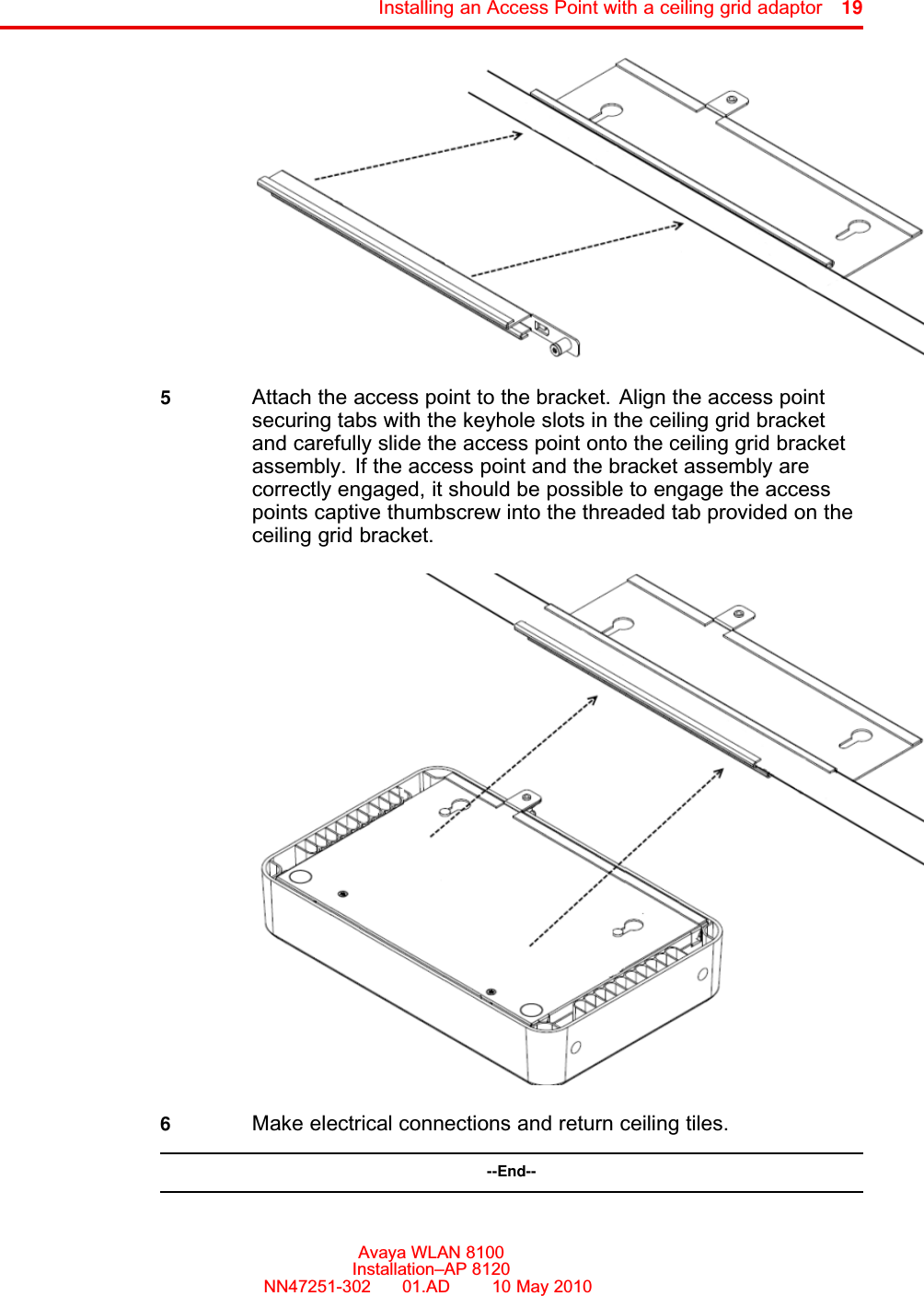
Avaya AP8120 802.11abgn Access Point User Manual AP 8120 Installation NN47251 302 01 AD IAP
Avaya, Inc. 802.11abgn Access Point AP 8120 Installation NN47251 302 01 AD IAP
Avaya >
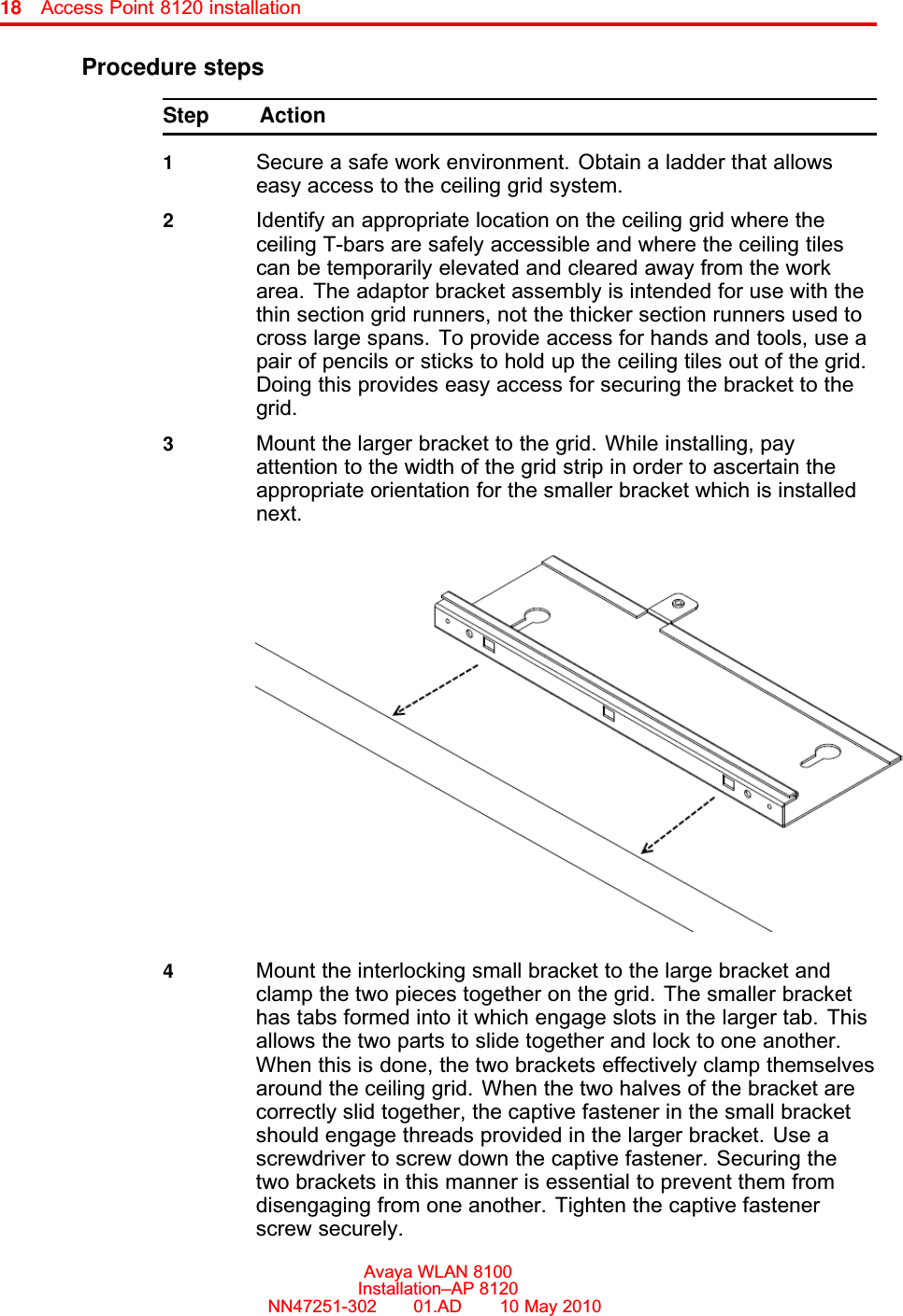
Contents
- 1. User Manual
- 2. AP 8120_Installation_NN47251-302_01_AD_IAP
- 3. AP 8120_Regulatory_Doc_NN47251-104_01 02_REGAP
- 4. NN47251-104 02.02 REGAP8120
- 5. NN47251-109 01.02 REGAP8120E
AP 8120_Installation_NN47251-302_01_AD_IAP