Authinx VT50A WIRELESS AUDIO/VIDEO SENDER User Manual VK50A OM pmd
Authinx Inc. WIRELESS AUDIO/VIDEO SENDER VK50A OM pmd
UserManual.wiki
>
Authinx
>
VT50A User Manual
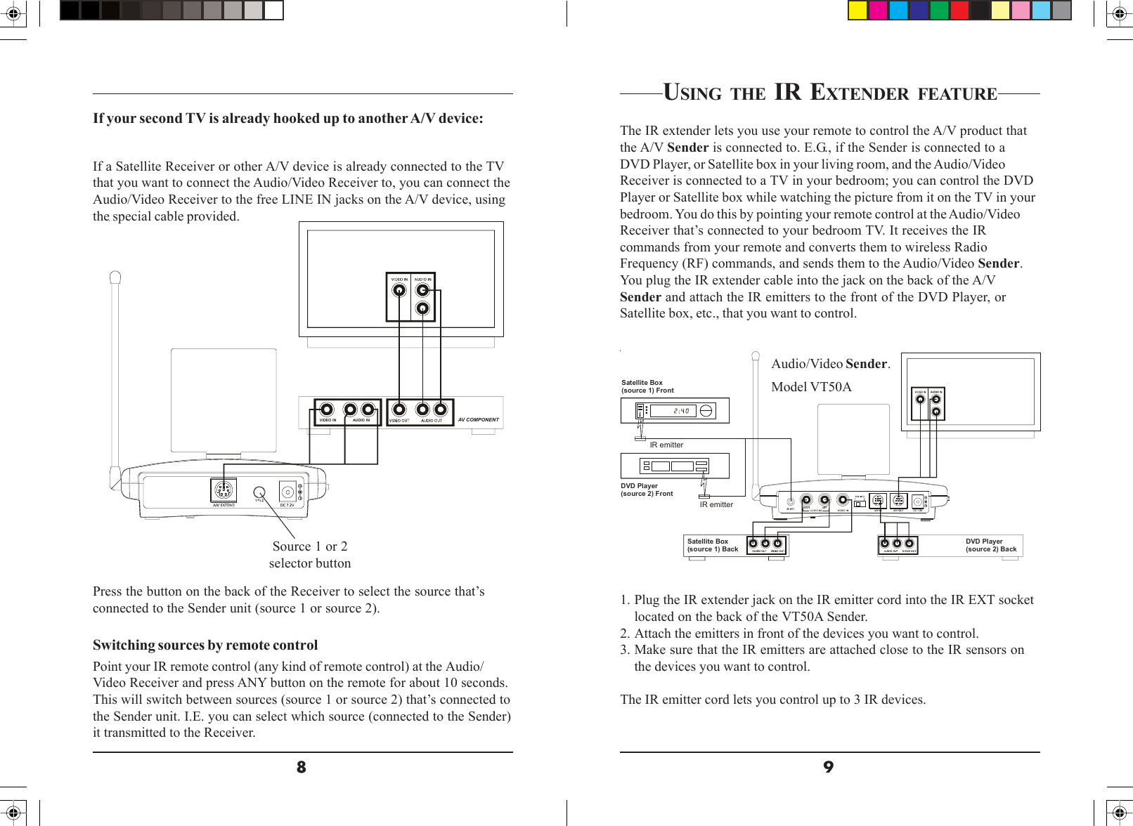
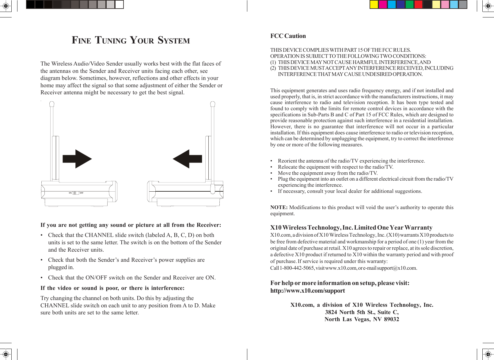
USERS MANUAL
Navigation menu
Upload a User Manual
Namespaces
Wiki Guide
HTML
PDF
Info
Views
User Manual
Discussion / Help
Navigation