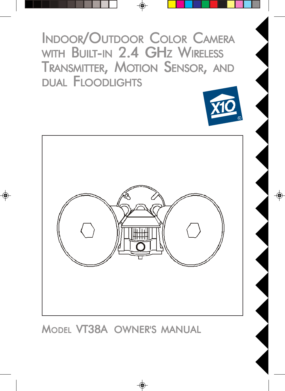
Authinx VT38A Indoor/Outdoor Camera w/2.4GHz transmitter. User Manual VT38A OM pm6

Authinx Inc. Indoor/Outdoor Camera w/2.4GHz transmitter. VT38A OM pm6

Exhibit D Users Manual per 2 1033 b3

IIIIINDOORNDOORNDOORNDOORNDOOR/O/O/O/O/OUTDOORUTDOORUTDOORUTDOORUTDOOR C C C C COLOLOLOLOLOROROROROR C C C C CAMERAAMERAAMERAAMERAAMERAWITHWITHWITHWITHWITH B B B B BUILUILUILUILUILTTTTT-----INININININ 2.4 GH 2.4 GH 2.4 GH 2.4 GH 2.4 GHZZZZZ W W W W WIRELESSIRELESSIRELESSIRELESSIRELESSTTTTTRANSMITTERRANSMITTERRANSMITTERRANSMITTERRANSMITTER, M, M, M, M, MOOOOOTIONTIONTIONTIONTION S S S S SENSORENSORENSORENSORENSOR, , , , ,  ANDANDANDANDANDDUDUDUDUDUALALALALAL F F F F FLLLLLOODLIGHTSOODLIGHTSOODLIGHTSOODLIGHTSOODLIGHTSMMMMMODELODELODELODELODEL VT38A  VT38A  VT38A  VT38A  VT38A  OWNER'S MANUALOWNER'S MANUALOWNER'S MANUALOWNER'S MANUALOWNER'S MANUAL
22222FCC CFCC CFCC CFCC CFCC CAUTIONAUTIONAUTIONAUTIONAUTIONTHIS DEVICE COMPLIES WITH PART 15 OF THE FCC RULES.OPERATION IS SUBJECT TO THE FOLLOWING TWO CONDITIONS:(1) THIS DEVICE MAY NOT CAUSE HARMFUL INTERFERENCE, AND(2) THIS DEVICE MUST ACCEPT ANY INTERFERENCE RECEIVED, INCLUDINGINTERFERENCE THAT MAY CAUSE UNDESIRED OPERATION.This equipment generates and uses radio frequency energy, and if not installed andused properly, that is, in strict accordance with the manufacturers instructions, itmay cause interference to radio and television reception. It has been type tested andfound to comply with the limits for remote control devices in accordance with thespecifications in Sub-Parts B and C of Part 15 of FCC Rules, which are designed toprovide reasonable protection against such interference in a residential installation.However, there is no guarantee that interference will not occur in a particularinstallation. If this equipment does cause interference to radio or televisionreception, which can be determined by unplugging the equipment, try to correct theinterference by one or more of the following measures.• Reorient the antenna of the radio/TV experiencing the interference.• Relocate the equipment with respect to the radio/TV.• Move the equipment away from the radio/TV.• Plug the equipment into an outlet on a different electrical circuit from the radio/TVexperiencing the interference.• If necessary, consult your local Dealer for additional suggestions.NONONONONOTETETETETE::::: Modifications to this product will void the user's authority to operate this I I I I INTRODUCTIONNTRODUCTIONNTRODUCTIONNTRODUCTIONNTRODUCTION          Your Wireless Motion Activated Camera consists of a Color Video Camera withbuilt-in 2.4 GHz transmitter. It is activated by its built-in Motion Sensor so thatwhen someone approaches your home, the camera turns on and also turns onthe attached floodlights to light up the area that the camera sees (bulbs notincluded). The camera transmits its picture and sound via a built-in 2.4 GHztransmitter, to a Video Receiver (sold separately) which you connect to a TVanywhere in your home. The Camera sends the wireless signals (even throughwalls, up to 100 ft.). The Video Receiver converts the signals back to video andaudio signals and feeds them through a cable to your TV's COAX or A/V inputjacks.You can purchase additional Motion Activated Cameras (up to 4) so you canhave a multiple camera system. You can then set all cameras to the samechannel as the receiver and turn the cameras on and off remotely so as to onlyever have one camera turned on at a time, and displayed on your TV.
33333CCCCCONTROLSONTROLSONTROLSONTROLSONTROLS     ANDANDANDANDAND C C C C CONNECTIONSONNECTIONSONNECTIONSONNECTIONSONNECTIONSFFFFFRONTRONTRONTRONTRONTVVVVVIEWIEWIEWIEWIEWBulbs notincludedBBBBBOOOOOTTTTTTTTTTOMOMOMOMOM V V V V VIEWIEWIEWIEWIEW ( ( ( ( (WITHWITHWITHWITHWITH     LIDLIDLIDLIDLID     CLCLCLCLCLOSEDOSEDOSEDOSEDOSED)))))SSSSSIDEIDEIDEIDEIDE V V V V VIEWIEWIEWIEWIEWCamera Motion SensorControls under thisweatherproof lid.Remove clear cap if you need to refocus thecamera. Replace to keep rain out.
44444Whi teBlackWhi teBlackWhi teBlackBlueWhi teWhiteBlackHouse WiringAAAAASSEMBLINGSSEMBLINGSSEMBLINGSSEMBLINGSSEMBLING     THETHETHETHETHE     PPPPPARTSARTSARTSARTSARTSReferring to the diagram below:1. Screw the base of each lamp holder into the outer holes on the mountingplate.2. Rotate the locking ring on each lamp holder towards the plate until thelamp holder is secure against the plate.3. Screw the threaded end of the motion activated camera into the centerhole on the mounting plate.4. Lock the motion activated camera into place using the locking ring.5. Locate each lamp holder's WHITE wire and one of the WHITE wires fromthe motion activated camera and twist all three wires together using a wirenut (supplied).6. Locate each BLACK wire from the lamp holders and connect them both tothe BLUE wires from the motion activated camera, again using a wire nut.Make sure no bare whiskers of wire stick out (cover with electrical tape ifnecessary).Bulbs notincludedCameraMotion Sensor
55555IIIIINSTNSTNSTNSTNSTALLINGALLINGALLINGALLINGALLING     THETHETHETHETHE A A A A ASSEMBLSSEMBLSSEMBLSSEMBLSSEMBLYYYYYReferring to the diagram below:You can install the motion activated camera in a wall box that is power at alltimes or in a wall box that is controlled by a wall switch, but if it is poweredfrom a wall switch, make sure you leave the switch on at all times. Turning theswitch off will completely disable the motion activated camera.CACACACACAUTIONUTIONUTIONUTIONUTION::::: To prevent severe damage to the unit, do not connect it to a wallbox that is controlled by any kind of dimmer of remote controlled switch.WARNING:WARNING:WARNING:WARNING:WARNING: Before making the following connections, be sure the power tothe junction box you are installing the motion activated camera into is turnedoff. If not, a serious shock hazard will exist.1. Install the gasket (supplied) onto the junctions box, and route the housewiring through the gasket.2. Connect the house wiring's bare copper wired to the grounding screw onthe mounting plate.3. Connect WHITE wire from the motion activated camera to the housewiring's WHITE wire, using a wire nut.4. Connect BLACK wire from the motion activated camera to the housewiring's BLACK wire, using a wire nut.Make sure no bare whiskers of wire stick out (cover with electrical tape ifnecessary).5. Secure the mounting plate to the junction box using the screws supplied.6. Secure the insulating ring in each lamp holder and screw in a bulb (max150W, not supplied) into each lamp holder.
66666CCCCCONTROLSONTROLSONTROLSONTROLSONTROLS     ANDANDANDANDAND C C C C CONNECTIONSONNECTIONSONNECTIONSONNECTIONSONNECTIONSYour motion activated camera turns on whenever someone approaches yourhome and also turns on the connected floodlights to light up the area that thecamera sees. The camera transmits its picture and sound to a 2.4 GHzreceiver (sold separately) which you connect to your TV. Open the lid on theunderside of the motion activated camera to reveal the controls below.ACOMEGIKADUSK CONTROLCHANNELCBDTIME DELAYUNIT CODEUNIT CODEHOUSE CODE131513 57911LIGHTMAX.DARKMIN.+1You set the channel switch (A, B, C, orD) to match the setting on the receiver.When the camera turns on ittransmits a wireless RadioFrequency (RF) command toturn off other cameras in agroup of 4 (requires an X10Transceiver (sold separately).The setting on these dials setsthe Housecode and Unit Codefor this camera.You can set it to detectmotion at all times or onlywhen it gets dark.The camera turnsoff a short timeafter motion hasstopped (adjustedby this dial).You can turn the floodlights andthe camera on from other X10remote controls that plug intoany outlet anywhere in yourhome. You set the Housecodedial to the same letter you set onyour X10 controller, and you setthe Unit Code to a numberbetween 1 and 16.
77777TO TVAUDIOVIDEOAUDIOVID EOTVTO TV AUDIOVIDEOTV12UHF/VHFANTENNATO TVANTENNACCCCCONNECTINGONNECTINGONNECTINGONNECTINGONNECTING     THETHETHETHETHE R R R R RECEIVERECEIVERECEIVERECEIVERECEIVER ( ( ( ( (SOLDSOLDSOLDSOLDSOLDSEPSEPSEPSEPSEPARAARAARAARAARATELTELTELTELTELYYYYY)))))1. Connect a set of Audio/Video cables to theA/V OUT jacks on the VR31A VideoReceiver. Connect the other end to your TV(use Yellow for video, and either L or Rchannel for audio). Note, VR36A receiversdo not have an audio output.2. Plug the Video Receiver's Power Supply jackinto the Video Receiver and plug the powersupply into a 120 volt wall outlet.3. Turn the Video Receiver's power switch (onside of unit) on.4. Set the channel switch to the same letter as you set on the camera, A, B, C,or D.5. Position the Video Receiver in a convenient location such as on top of the TVand orient the antenna so that the flat side points in the direction where youset up the Camera.IIIIIFFFFF     YYYYYOUROUROUROUROUR TV  TV  TV  TV  TV  DOESDOESDOESDOESDOES     NONONONONOTTTTT     HAHAHAHAHAVEVEVEVEVE A/V  A/V  A/V  A/V  A/V  CONNECTCONNECTCONNECTCONNECTCONNECTORSORSORSORSORSYou can use a coaxial cable(supplied with Model VR31Areceivers only) to connectthe TV OUT socket on theVR31A Video Receiver tothe Antenna input on yourTV. If you already have anantenna connected to yourTV, you will need to use aTV antenna splitter.Set your TV and the TVChannel switch on the VideoReceiver (on bottom) to thesame channel (3 or 4).Note model VR36Areceivers do not have a COAX output.
88888Outdoors IndoorsIIIIIFFFFF     YOURYOURYOURYOURYOUR TV  TV  TV  TV  TV  ISISISISIS     ALREADYALREADYALREADYALREADYALREADY     HOOKEDHOOKEDHOOKEDHOOKEDHOOKED     UPUPUPUPUP     TOTOTOTOTOAAAAA DBS R DBS R DBS R DBS R DBS RECEIVERECEIVERECEIVERECEIVERECEIVER     OROROROROR     OOOOOTHERTHERTHERTHERTHER A/V A/V A/V A/V A/VDEVICEDEVICEDEVICEDEVICEDEVICEIf a DBS Receiver or other A/V component isconnected to the TV using A/V cables, youcan connect the Video Receiver to the freeLINE IN jacks on the component. If there areno LINE IN jacks, you will need to use a TVantenna splitter as described earlier (VR31Areceivers only).FFFFFINEINEINEINEINE T T T T TUNINGUNINGUNINGUNINGUNING     YYYYYOUROUROUROUROUR S S S S SYSTEMYSTEMYSTEMYSTEMYSTEM     The Wireless Motion Activated Camera usually works best with the flat faces ofthe antennas on the Camera and Receiver unit facing each other (see diagrambelow). Sometimes, however, reflections and other effects in the home mayaffect the signal so that some adjustment of either the Sender or Receiverantenna may be necessary to get the best the signal.AntennaAntenna is inside unit (Facing in thedirection of the arrow)
99999 T T T T TROUBLESHOOROUBLESHOOROUBLESHOOROUBLESHOOROUBLESHOOTINGTINGTINGTINGTING     If you do not see a picture on your TVIf you do not see a picture on your TVIf you do not see a picture on your TVIf you do not see a picture on your TVIf you do not see a picture on your TV:::::Check that the receiver and the camera are on the same letter channel (A, B,C, or D). The channel switch on the camera is located under the lid on thebottom of the unit. Make sure you close the lid and screw it tightly shutafterwards.There is a power light on the front of the receiver. Check that the power switchon the side of the receiver is ON.Verify that your connections to the TV are correct. If you are using the RCAjacks, make sure you are using the appropriate input mode for your TV, trypressing the A-B button or Video button on your TV's remote to change theinput mode (consult your TV's owner's manual, if necessary). If you are usingthe Coax cable (VR31A receiver only), verify that the Receiver and the TV areon the same channel (3 or 4).If you connected the Receiver to a VCR and then connected the VCR to your TV,you might need to turn the VCR OFF to see the camera picture on your TV. Oryou might need to turn the VCR on, AND set it to record the picture from thecamera, in order to see the picture on your TV. Or you might need to press theA-B button on your VCR's remote control. Consult your VCR's owner's manualfrom more information.If you get a picture but the quality is poor:If you get a picture but the quality is poor:If you get a picture but the quality is poor:If you get a picture but the quality is poor:If you get a picture but the quality is poor:Take a look at what the video signal is passing through or near to get to thereceiver. Metal objects and electromagnetic fields can distort the signal. Try tokeep the receiver as far away from other devices as the RCA or Coax cablesallow. In most cases, relocating the transmitter or receiver a few feet is enoughto avoid the source of interference.Try unplugging/turning off any electromagnetic interference producing devices,such as a microwave oven, baby monitor, computer, wireless LAN, wirelessspeakers, cordless phone, cell phone, etc.Other 2.4 GHz devices can distort the camera's picture and/or cause buzzingin the audio. If you are experiencing interference between X10 cameras orVideo Senders and some other equipment that uses 2.4 GHz, you might wantto check the other device's owner's manual for the frequencies of each channelthat it uses. X10 cameras and Video Senders use the following frequencies:Channel A: 2.411 GHz, Chan B: 2.434 GHz, Chan C: 2.453 GHz, Chan D:2.473 GHz We recommend using a frequency on the other device that isfarthest from channel A or D, depending on which side of the band the otherdevice is transmitting. Otherwise you will need to discontinue use of the devicewhile using our video equipment.
1010101010If you are having difficulty turning the camera on/off remotely:If you are having difficulty turning the camera on/off remotely:If you are having difficulty turning the camera on/off remotely:If you are having difficulty turning the camera on/off remotely:If you are having difficulty turning the camera on/off remotely:Try plugging the transceiver (the module with the antenna) into a different ACoutlet.How do you focus the camera?How do you focus the camera?How do you focus the camera?How do you focus the camera?How do you focus the camera?The motion activated camera is shipped preset to be in focus for normal use,but if you want to change the focus you can remove the clear plastic cover androtate the inner portion of the lens. It might be a bit tight. Try turning itcounterclockwise first. If you turn it clockwise do not force or over tighten it.Replace the clear plastic cover to keep the rain out.If the motion sensor doesn't see you:If the motion sensor doesn't see you:If the motion sensor doesn't see you:If the motion sensor doesn't see you:If the motion sensor doesn't see you:Check the dusk control setting to see if it is set to detect motion at all times oronly at night. Adjust if necessary.Check that you are walking across the path of the sensor. It is more sensitive inthis direction than if you walk towards it.FFFFFor more help please visit wwwor more help please visit wwwor more help please visit wwwor more help please visit wwwor more help please visit www.x10.com/support.x10.com/support.x10.com/support.x10.com/support.x10.com/supportSpecificationsSpecificationsSpecificationsSpecificationsSpecificationsImager CMOS SensorFormat 1/3"Array Size NTSC: 510 X 492Resolution: 310 TV LinesScanning: 2:1 InterlaceAuto Shutter: 1/60 to 1/15,000 sec.Minimum Illumination: 3 LUX (f1.9)Operating Temp.: 32 to 131 FHumidity Limits 0 - 95%Field of View: 38.5 deg.Power Required: 120VACMore sensitive Less sensitiveSensorSensorArrows denotemotion paths
111111111112 MONTH LIMITED WARRANTY12 MONTH LIMITED WARRANTY12 MONTH LIMITED WARRANTY12 MONTH LIMITED WARRANTY12 MONTH LIMITED WARRANTYX10.COM A DIV. OF X10 WIRELESS TECHNOLOGY, INC. (X10) WARRANTSITS PRODUCTS TO BE FREE FROM DEFECTIVE MATERIAL ANDWORKMANSHIP FOR A PERIOD OF ONE (1) YEAR FROM THE ORIGINALDATE OF PURCHASE AT RETAIL. X10 AGREES TO REPAIR OR REPLACE, ATITS SOLE DISCRETION, A DEFECTIVE X10 PRODUCT IF RETURNED TO X10WITHIN THE WARRANTY PERIOD AND WITH PROOF OF PURCHASE.IF SERVICE IS REQUIRED UNDER THIS WARRANTY:1. CALL 1-800-675-3044, OR VISIT WWW.X10.COM, OR E-MAILSALES@X10.COM TO OBTAIN A RETURN MERCHANDISEAUTHORIZATION (RMA) NUMBER.2. RETURN THE DEFECTIVE UNIT POSTAGE PREPAID TO THE ADDRESSBELOW3. ENCLOSE A CHECK FOR $4.00 TO COVER HANDLING AND RETURNPOSTAGE.4. ENCLOSE A DATED PROOF OF PURCHASE.5. X10 IS NOT RESPONSIBLE FOR SHIPPING DAMAGE. UNITS TO BERETURNED SHOULD BE PACKED CAREFULLY.THIS WARRANTY DOES NOT EXTEND TO ANY X10 PRODUCTS WHICHHAVE BEEN SUBJECT TO MISUSE, NEGLECT, ACCIDENT, INCORRECTWIRING OR TO USE IN VIOLATION OF OPERATING INSTRUCTIONSFURNISHED BY US, NOR EXTEND TO ANY UNITS ALTERED OR REPAIREDFOR WARRANTY DEFECT BY ANYONE OTHER THAN X10. THIS WARRANTYDOES NOT COVER ANY INCIDENTAL OR CONSEQUENTIAL DAMAGES ANDIS IN LIEU OF ALL OTHER WARRANTIES EXPRESSED OR IMPLIED AND NOREPRESENTATIVE OR PERSON IS AUTHORIZED TO ASSUME FOR US ANYOTHER LIABILITY IN CONNECTION WITH THE SALE OF OUR PRODUCTS.SOME STATES DO NOT ALLOW LIMITATIONS ON HOW LONG AN IMPLIEDWARRANTY LASTS, AND/OR THE EXCLUSION OR LIMITATION OFINCIDENTAL OR CONSEQUENTIAL DAMAGES SO THE ABOVE LIMITATIONSAND EXCLUSIONS MAY NOT APPLY TO THE ORIGINAL CUSTOMER. THISWARRANTY GIVES YOU SPECIFIC RIGHTS AND YOU MAY ALSO HAVEOTHER RIGHTS WHICH VARY FROM STATE TO STATE.X10.com, a division of X10 Wireless Technology, Inc.(Returns Depot), 3824 North 5th St., Suite C,North Las Vegas, NV 89030
VT38A-8/01X10.com, a division of X10 Wireless Technology, Inc.(Returns Depot), 3824 North 5th St., Suite C,North Las Vegas, NV 89030WWWWWeb Site: wwweb Site: wwweb Site: wwweb Site: wwweb Site: www.x10.com.x10.com.x10.com.x10.com.x10.com

Navigation menu