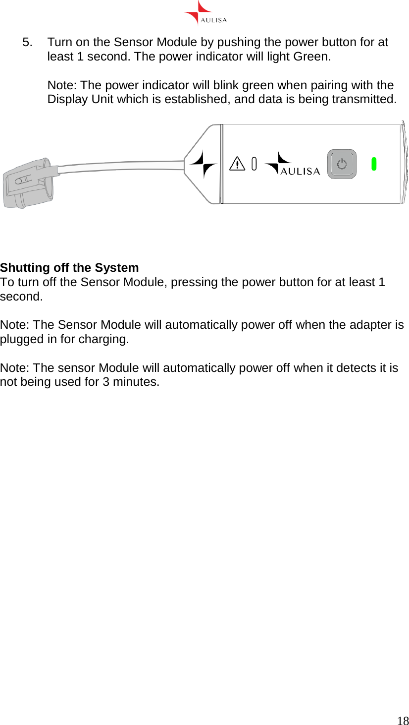
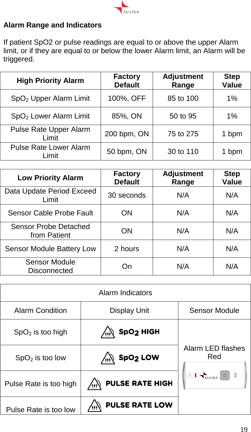
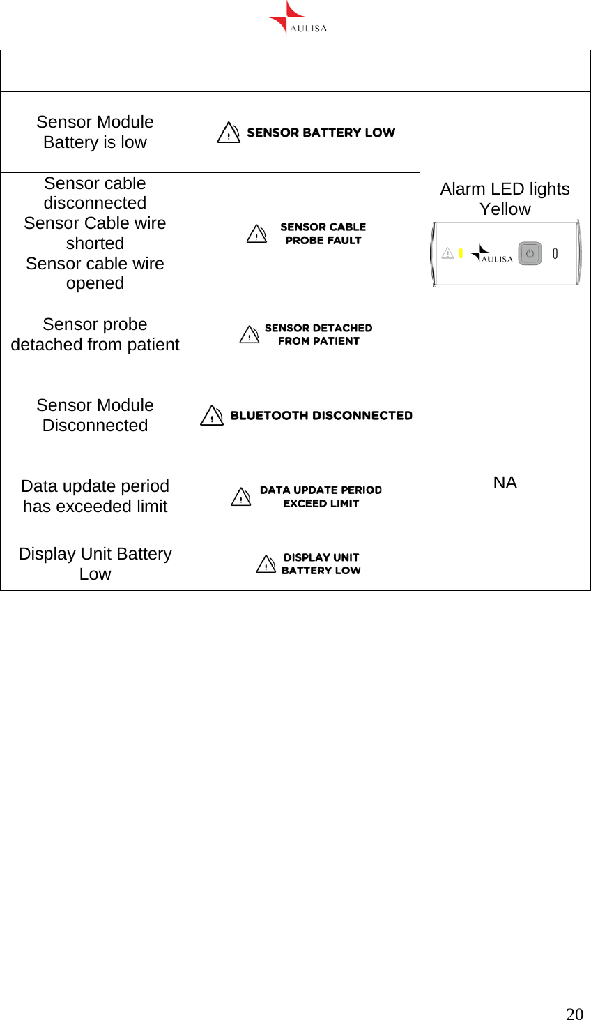
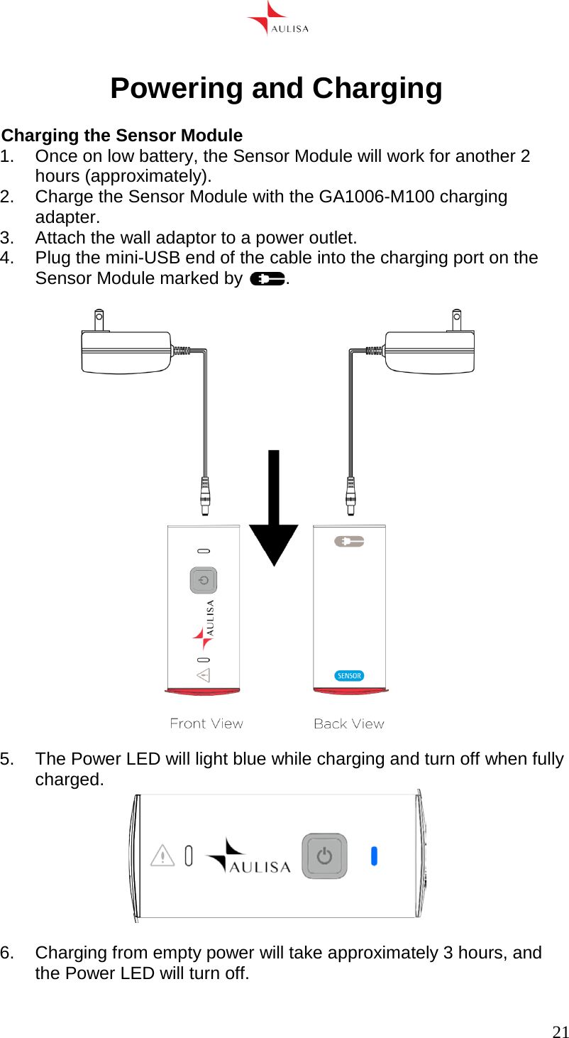
Aulisa Medical Devices Technologies GA1001 Bluetooth 4.0 BTLE Sensor User Manual

Taiwan Aulisa Medical Devices Techonologies Inc. Bluetooth 4.0 BTLE Sensor

User Manual

     1  Aulisa Guardian Angel™ GA1001 Sensor Module Instruction For Use              Taiwan Aulisa Medical Devices Technologies, Inc. 10F., No.3-2, Park St., Nangang Dist., Taipei City 115, Taiwan (R.O.C) Tel +886-2-2655-7297 www.aulisa.com ©2016 Taiwan Aulisa Medical Devices Technologies, Inc
     2    Warning! Federal law (USA) restricts this device to sale by or on the order of a licensed health care professional only.   Warning! Read this entire manual carefully before using the Aulisa GA1000 Digital Vital Sign Monitoring System  At the time of publication, this manual is believed to be accurate and up-to-date. In the interest of continued product development, Taiwan Aulisa Medical Devices Technologies, Inc. reserves the right to make changes and improvements to this manual and the products described within at any time, without notice or obligation.  References to “Aulisa” in this manual shall imply Taiwan Aulisa Medical Devices Technologies, Inc.  Aulisa is a registered trademark of Taiwan Aulisa Medical Devices Technologies, Inc.  Pre-Sense is a registered trademark of Taiwan Aulisa Medical Devices Technologies, Inc.    Taiwan Aulisa Medical Devices Technologies, Inc. 10F., No.3-2, Park St., Nangang Dist., Taipei City 115, Taiwan (R.O.C) Tel +886-2-2655-7297 www.aulisa.com ©2016 Taiwan Aulisa Medical Devices Technologies, Inc.
     3  Table of contents GUIDE TO SYMBOLS ............................................................................................................. 4 PRECAUTIONS FOR USE ...................................................................................................... 5 USING THE GA1001 ............................................................................................................. 12 INDICATIONS FOR USE ................................................................................................................ 13 CONTROLS, PORTS, INDICATORS, A N D   DI S P L A Y S ..................................................................... 13 SHU TTI NG  OF F  TH E SYSTEM ....................................................................................................... 18 AL A R M   RANGE AND INDICATORS ............................................................................................... 19 POWERING AND CHARGING ............................................................................................. 21 C A R E   A N D   M A I N T E N A N C E  ................................................................................................ 23 SPECIFICATIONS ................................................................................................................. 24 PARTS AND ACCESSORIES............................................................................................... 26 SERVICE, SUPPORT, AND   W A R R A N T Y  ........................................................................... 27 TROUBLESHOOTING ........................................................................................................... 29
     4  Guide to symbols  Table 1: Guide to symbols Symbol Description  Warning!  Caution!  Consult Instructions for Use.  Type BF-Applied Part (patient isolation from electrical shock)  Indicates separate collection for electrical and electronic equipment (WEEE).  Non-ionizing electromagnetic radiation. Equipment includes RF transmitters. Interference may occur in the vicinity of equipment marked with this symbol.  Manufacturer    Serial number  Lot number
     5  Precautions for Use   Caution! Contraindications  1.  Do not use any part of this system in an MRI environment. 2.  Explosion Hazard: Do not use this system in an explosive atmosphere or in the presence of flammable anesthetics or gases. 3.  This device is not a replacement for a caregiver.   Warning! Warnings  1.  This system is intended only as an adjunct in patient assessment. It must be used in conjunction with other methods of assessing clinical signs and symptoms. 2.  A functional tester cannot be used to assess the accuracy of a pulse oximeter probe or a pulse oximeter monitor. Pulse oximeters do not require calibration. 3.  Oximeter readings may be affected by the use of an electrosurgical unit. 4.  Only use Aulisa manufactured sensors. These sensors are manufactured to meet the accuracy specifications for Aulisa Digital Vital Sign Monitoring Systems. Using other manufacturers’ sensors can result in improper pulse oximeter performance and patient injury may occur. 5. The operator must verify the compatibility of the sensor probe with the Vital Sign Monitoring System before use, otherwise patient injury can result 6.  Misapplication of the sensor probe with excessive pressure for prolonged periods can induce pressure injury 7.  Do not use a damaged sensor. 8.  Do not use in or around water or any other liquid. 9.  Only use this vital sign monitoring system with GA1006 power adapters provided by Aulisa. 10. This vital sign monitoring system is designed to determine functional oxygen saturation, the percentage of arterial oxygen saturation of functional hemoglobin. Significant levels of dysfunctional hemoglobin, such as methemoglobin, might affect the accuracy of the measurement.
     6  11. Use the vital sign monitoring system only when the components are installed within the specified distances from the monitored patient – approximately 10 meters (10.9 yards) spherical radius from pulse oximetry Sensor Module to the wireless Display Unit. Moving outside this range may cause missing, lost, and/or inaccurate data. 12. Loss of monitoring can result if any objects hinder the pulse measurement. Ensure that no blood flow restrictors (e.g., blood pressure cuff) hinder pulse measurements. 13. Do not place cord within reach of children, infants, and neonates. 14. This product is not a substitution for adult supervision. 15. Always refer to the Instructions For use for full warnings and instructions. 16. Failure to follow instructions and warnings may result in serious injury or death.  Caution! Cautions  1.  This equipment complies with International Standard EN 60601-1-2:2001 for electromagnetic compatibility for medical electrical equipment and/or systems. This standard is designed to provide reasonable protection against harmful interference in a typical medical installation. However, because of the proliferation of radio-frequency transmitting equipment and other sources of electrical noise in healthcare and other environments, it is possible that high levels of interference due to close proximity or strength of a source might disrupt the device’s performance. 2.  If this vital sign monitoring system fails to respond as described, discontinue use until the situation is corrected by qualified personnel. 3.  Cardiogreen and other intravascular dyes may affect the accuracy of SpO2 measurements. 4. The sensor might not work on cold extremities due to reduced circulation. Warm or rub the extremity to increase circulation, or reposition the sensor. 5.  This system might misinterpret motion as good pulse quality. Minimize motion of the monitored site. 6.  Some nail polish colors or artificial nails can reduce light transmission and affect SpO2 accuracy. 7.  Inspect the sensor application site at least every 6 to 8 hours to ensure correct sensor alignment and skin integrity. Patient sensitivity to sensors may vary due to medical status or skin condition.
     7  8.  The frequency of sensor relocation should be every 6-8 hours to ensure correct sensor alignment and skin integrity. Patient sensitivity to sensors may vary due to medical status or skin condition. 9.  Do not place liquids on top of this pulse oximetry system. 10. Do not immerse the pulse oximetry system or sensors in any liquids. 11. Do not use caustic or abrasive cleaning agents on the unit or sensors. 12. Do not gas sterilize or autoclave this pulse oximetry system. 13. Dress all cords accordingly to prevent tripping and tangling. 14. Batteries might leak or explode if used or disposed of improperly. 15. Follow local governing ordinances and recycling instructions regarding disposal or recycling of the device and device components, including batteries. 16. Do not fasten the Sensor Module too tightly around the patient’s wrist or ankle. Inaccurate readings and patient discomfort could result. 17. Caution: Exposure to Radio Frequency Radiation. The Sensor Module has been tested and meets allowed limits for exposure
     8  Declaration of Conformity with FCC for Electromagnetic Compatibility Taiwan Aulisa Medical Devices Technologies, Inc. of 10F., No.3-2, Park St., Nangang Dist., Taipei City 115, Taiwan (R.O.C) declares under its sole responsibility that the Aulisa Model GA1001, to which this declaration relates, comply with part 15 of the FCC Rules. Operation is subject to the following two conditions: (1) this device may not cause harmful interference, and (2) this device must accept any interference received, including interference that may cause undesired operation.  Federal Communications Commission (FCC) Notice This equipment has been tested and found to comply with the limits for a Class B digital device, pursuant to part 15 of the FCC Rules. These limits are designed to provide reasonable protection against harmful interference in a residential installation. This equipment generates, uses and can radiate radio frequency energy and, if not installed and used in accordance with the instructions, may cause harmful interference to radio communications. However, there is no guarantee that interference will not occur in a particular installation. If this equipment does cause harmful interference to radio or television reception, which can be determined by turning the equipment off and on, the user is encouraged to try to correct the interference by one or more of the following measures: (1) Reorient or relocate the receiving antenna. (2) Increase the separation between the equipment and receiver. (3) Connect the equipment into an outlet on a circuit different from that to which the receiver is connected. (4) Consult the dealer or an experienced radio/TV technician for help.  The Aulisa Model GA1001 is designed and manufactured not to exceed the emission limits for exposure to radio frequency (RF) energy set by the Federal Communications Commission of the U.S. Government. These limits are part of comprehensive guidelines and establish permitted levels of RF energy for the general population. The guidelines are based on the safety standards previously set by both U.S. and international standards bodies. This equipment has been shown to be capable of compliance for localized specific absorption rate (SAR) for uncontrolled environment/ general population exposure limits specified in ANSI/IEEE Std. C95.1-1992 and has been tested in accordance with the measurement procedures specified in IEEE Std. 1528-200X (Draft 6.5, January 2002).  RF Exposure: For body worn operation, to maintain compliance with FCC RF exposure guidelines, use only accessories that contain no metallic components. RF exposure separation distance is 5 mm. Use of other accessories may violate FCC RF exposure guidelines and should be avoided.
     9  The FCC requires the user to be notified that any changes or modifications to this device that are not expressly approved by Taiwan Aulisa Medical Devices Technologies, Inc. may void the user’s authority to operate the equipment.    Warning! No modifications to this device are allowed that in any way affect or alter its antenna or antenna configuration.  FCC Part 15.19 Warning Statement This device complies with Part 15 of the FCC Rules. Operation is subject to the following two conditions: (1) this device may not cause harmful interference, and (2) this device must accept any interference received, including interference that may cause undesired operation.  FCC Part 15.21 Warning Statement  The user manual for an intentional or unintentional radiator shall caution the user that causes or modifications not expressly approved by the party responsible for compliance could void the user’s authority to operate the equipment.   GA1001 Sensor NOTE: THE GRANTEE IS NOT RESPONSIBLE FOR ANY CHANGES OR MODIFICATIONS NOT EXPRESSLY APPROVED BY THE PARTY RESPONSIBLE FOR COMPLIANCE. SUCH MODIFICATIONS COULD VOID THE USER’S AUTHORITY TO OPERATE THE EQUIPMENT.
     10  Manufacturer Declaration  Scientific principal The GA1001 measures SpO2 and Pulse rate based on transmittance technology, measuring the absorbance of red and infrared light passed through the tissue.  Safety and performance testing The Aulisa Guardian Angel GA1001 Digital Vital Sign Monitoring Sensor Module conforms to the following international standards:  Performance and safety ISO 80601-2-61:2011 Particular requirements for basic safety and essential performance of pulse oximeter equipment  Electromagnetic Emissions IEC 60601-1-2:2014 General requirements for basic safety and essential performance - Collateral Standard: Electromagnetic disturbances - Requirements and tests   Accuracy testing  SpO2 Accuracy SpO2 accuracy testing is performed by clinical trials on healthy adult subjects with varying skin pigmentation in an independent research laboratory through induced hypoxia studies. Analysis of bias1 was performed vs. Hemoximeter data. The limits of agreement shown are calculated per: Bland JM, Altman D. (2007) Agreement between methods of measurement with multiple observations per individual. Journal of Biopharmaceutical Statistics 17, 571 – 582. Root mean square error (RMS error) is calculated as follows:  RMS Error = ()  1Bias is defined as the monitor under test reading minus the hemoximeter reading.  Note: Because pulse oximeter equipment measurements are statistically distributed, only about two-thirds of Aulisa GA1001 measurements can be expected to fall within ±Arms of the value measured by a co-oximeter.
     11  Pulse rate Accuracy Pulse rate accuracy has been tested against an electronic pulse simulator over the range of 30 to 300 bpm at 0.1 step of pulse amplitude from 0.5% to 20%. RMS Error = ()  Where PRAulisais the pulse rate measured by Aulisa GA1001 and PRSimulator is the simulator setting of pulse rate.   Equipment Response Time The GA1001 uses a moving average to determine the Pulse Rate and SpO2. The following table shows the equipment response time of the GA1001.  Equipment Delays Delay (Seconds) Data Averaging ≤ 4 seconds Alarm Condition Delay ≤ 4 seconds Alarm Signal Generation Delay 0 seconds Data Update Period 1 second
     12  Using the GA1001  This chapter describes how to use the Aulisa GA1001 Guardian Angel Digital Vital Sign Monitoring Sensor Module. The system includes the following components and accessories:  GA1001 Sensor Module (x2) GA1004 – SC100X Silicon finger sensor GA1005 – WB100 Sensor Module wristband GA1006 – M100 Sensor Module Charging Adaptor Instructions For Use  GA1001 Sensor Module (x2)  GA1004 – SC100X Silicon finger sensor  GA1005 – WB100 Sensor Module wristband
     13  GA1006 – M100 Sensor Module Charging Adaptor    Indications for Use  The AulisaTM Guardian AngelTM Model GA1001 Digital Vital Sign Monitoring Sensor Module is indicated for use in measuring and displaying functional oxygen saturation of arterial hemoglobin (SpO2) and pulse rate of adult, pediatric, infant, and neonate patients. It is indicated for spot-checking and / or continuous monitoring of patients during non-motion and under well-perfused conditions..  Controls, Ports, Indicators, and Displays  This section describes the Aulisa Guardian Angel displays, indicators, and controls for the Sensor Module.  Sensor Module The Sensor Module includes a transmitter and a sensor, which is worn by the patient for vital sign monitoring. It features sensors and electronics for vital sign measuring and analyzing. The sensors can be attached on the fingers, toes, or feet.
     14  Hardware Control Buttons  Power button Push this button to turn the Sensor Module on or off. Ports  Mini-USB Charging Port Charge the Sensor Module by connecting the supplied GA1006-M100 Sensor Module Charging Adaptor  Sensor Port Connect the Sensor to the Sensor Module through the sensor port. Display Icons and Indicators  Power button and Power Indicator This icon identifies the power button and power indicator.  Alarm Indicator This icon identifies the alarm indicator.  Setting up the GA1000 system Use the following procedure to set up the Aulisa GA1001 Digital Vital Sign Monitoring Sensor Module:  Wristband The wristband is used to secure the Sensor Module on a patient’s wrist. Secure the wristband onto the patient’s wrist with the transparent pocket facing outwards. Slip the Velcro end through the hole and loop around to secure the wristband.
     15   Adjust the wristband according to wrist size.  Sensor Module Use the following procedure to power on the Sensor Module and pair with the Display Unit(sold separately)..  Note: Please make sure to follow instructions in this particular order. Otherwise, an alarm will go off indicating cable disconnection or finger not detected..  1.  Attach the Sensor connector to the Sensor Module port end marked with  .
     16      Caution! Only use the sensors supplied or manufactured by Taiwan Aulisa Medical Devices Technologies, Inc. 2.  Insert the Sensor Module into the wristband mesh pocket.
     17    3. Put the GA1005-WB100 Wristband with the Sensor Module inside onto the left or right hand. 4.  Attach the Sensor probe to the thumb or finger.
     18  5.  Turn on the Sensor Module by pushing the power button for at least 1 second. The power indicator will light Green.  Note: The power indicator will blink green when pairing with the Display Unit which is established, and data is being transmitted.      Shutting off the System To turn off the Sensor Module, pressing the power button for at least 1 second.  Note: The Sensor Module will automatically power off when the adapter is plugged in for charging.  Note: The sensor Module will automatically power off when it detects it is not being used for 3 minutes.
     19  Alarm Range and Indicators  If patient SpO2 or pulse readings are equal to or above the upper Alarm limit, or if they are equal to or below the lower Alarm limit, an Alarm will be triggered.  High Priority A l a r m  Factory Default Adjustment Range Step Value SpO2 Upper Alarm Limit 100%, OFF 85 to 100 1% SpO2 Lower Alarm Limit 85%, ON 50 to 95 1% Pulse Rate Upper Alarm Limit 200 bpm, ON 75 to 275 1 bpm Pulse Rate Lower Alarm Limit 50 bpm, ON 30 to 110 1 bpm  Low Priority Alarm Factory Default Adjustment Range Step Value Data Update Period Exceed Limit 30 seconds N/A N/A Sensor Cable Probe Fault ON N/A N/A Sensor Probe Detached from Patient ON N/A N/A Sensor Module Battery Low 2 hours N/A N/A Sensor Module Disconnected On N/A N/A  Alarm Indicators Alarm Condition Display Unit Sensor Module  SpO2 is too high   Alarm LED flashes Red   SpO2 is too low    Pulse Rate is too high    Pulse Rate is too low
     20    Sensor Module Battery is low   Alarm LED lights Yellow  Sensor cable disconnected Sensor Cable wire shorted Sensor cable wire opened   Sensor probe detached from patient    Sensor Module Disconnected   NA  Data update period has exceeded limit   Display Unit Battery Low
     21   Powering and Charging  Charging the Sensor Module 1.  Once on low battery, the Sensor Module will work for another 2 hours (approximately). 2. Charge the Sensor Module with the GA1006-M100 charging adapter. 3.  Attach the wall adaptor to a power outlet. 4. Plug the mini-USB end of the cable into the charging port on the Sensor Module marked by  .    5.  The Power LED will light blue while charging and turn off when fully charged.   6.  Charging from empty power will take approximately 3 hours, and the Power LED will turn off.
     22   Caution! Only use cables and adaptors supplied or manufactured by Taiwan Aulisa Medical Devices Technologies, Inc.   Caution! The Sensor Module cannot be used to measure vital signs while it is being charged.
     23  Care and Maintenance  The advanced digital circuitry within the Sensor Module of this system requires no calibration or periodic maintenance.  Field repair of system circuitry is not possible. Do not attempt to open the case or repair the electronics. Opening the Sensor Module will damage the device and void the warranty. If the system is not functioning properly, please refer to the “Troubleshooting” section.  Cleaning the Sensor Module Sensors  Aulisa produces a wide variety of sensors for different applications and needs. Some sensors can be cleaned while some are disposable. To determine if your sensor can be cleaned, please identify the part number and follow the instructions below.  Sensor Model Number Sensor Material Cleaning instructions GA1004- FM100X Foam These sensors are disposable and therefore cannot be cleaned. GA1004- SC100X Silicon Clean with a soft cloth dampened with rubbing alcohol.    Warning! Do not immerse the device in liquid, and do not use caustic or abrasive cleaning agents on the device.
     24  Specifications  Aulisa GA1001 Digital Vital Sign Monitoring Sensor Module Blood Oxygen Saturation Display Range (SpO2) 0% to 100% Pulse Rate D i s p l a y   Range 30 to 290 bpm Accuracy Blood Oxygen Saturation (%SpO2) (± 1 S.D.) SC100M Silicon sensor (Pediatric)  70-100% ± 3 digits ENSC100L Silicon sensor (Adult)  70-100% ± 3 digits Pulse Rate SC100M Silicon sensor (Pediatric) ± 3% ENSC100L Silicon sensor (Adult)  ± 3% Measurement Wavelengths and Output Power Red 660 nanometers @ 1.8 mw nominal Infrared 905 nanometers @ 2 mw nominal Temperature Operating + 5°C to + 40°C Storage/Transportation – 25°C without relative humidity control + 70°C at a relative humidity up to 93 %, non-condensing Operating Altitude altitude ≤ 2 000 m. Atmospheric Pressure 700 hPa to 1060 hPa Humidity Operating 15% to 93%, non-condensing Storage/Transportation 10% to 95% relative humidity, non-condensing Sensor Module (Sensors integrated) Internal Power  Battery 3.7 V battery Operating Life 10 hours of continuous operation Dimensions  Without sensors 0.7” H x 1.3”   W   x   2.7” D 16 mm H x 32 mm W   x   68 mm D Weight 1 ounce 28 grams Ingress Protection IP22 Classifications per IEC 60601- 1 Type of Protection  Class I (when on AC power with ) Internally powered (on battery power)
     25  Degree of Protection Type BF-Applied Part Mode of Operation  Continuous
     26   Parts and Accessories  Parts and Accessories Part Number Sensor Module GA1001 Display Unit GA1003 Sensors Silicon Finger Sensor (Pediatric) GA1004 – SC100M Silicon Finger Sensor (Adult) GA1004 – ENSC100L Sensor Module Holder Sensor Module Wristband GA1005 – WB100 AC Adaptor Sensor Module charging adaptor GA1006 – M100  For more information about Aulisa parts and accessories, contact your distributor, or contact Aulisa at 1 (650) 813-1273 (USA).   Warning! Using sensors or accessories not by Taiwan Aulisa Medical Devices Technologies, Inc. may result in inaccurate measurements. Always use parts and accessories by Taiwan Aulisa Medical Devices Technologies, Inc.
     27  Service, Support, and Warranty  A return authorization number is required before returning any product to Aulisa. To obtain this return authorization number, contact Aulisa Customer Support:  United States of America Aulisa Medical Technologies, Inc. 999 Commercial St, Suite 208 Palo Alto, CA 94303 USA Tel (650) 813-1273  Taiwan Taiwan Aulisa Medical Devices Technologies, Inc. 10F., No.3-2, YuanQu St., Nangang Dist., Taipei City 115, Taiwan (R.O.C) Tel +886-2-2655-7297 www.aulisa.com ©2016 Taiwan Aulisa Medical Devices Technologies, Inc.  Warranty  Taiwan Aulisa Medical Devices Technologies, Inc., warrants to the purchaser, for a period of one year from the date of purchase, the Aulisa GA1001 Digital Vital Sign Monitoring Sensor Module. Aulisa warrants the Sensor Module for a period of one year from the date of purchase. Aulisa shall repair or replace any Sensor Module and integrated sensor(s) and Display Unit found to be defective in accordance with this warranty, free of charge, for which Aulisa has been notified by the purchaser by serial number that there is a defect, provided said notification occurs within the applicable warranty period. This warranty shall be the sole and exclusive remedy by the purchaser hereunder for any Aulisa GUARDIAN ANGEL GA1001 Digital Vital Sign Monitoring Sensor Module delivered to the purchaser which is found to be defective in any manner, whether such remedies be in contract, tort, or by law.  This warranty excludes cost of delivery to and from Aulisa. All repaired units shall be received by the purchaser at Aulisa place of business. Aulisa reserves the right to charge a fee for a warranty repair request on any Aulisa GUARDIAN ANGEL GA1001 Digital Vital Sign Monitoring Sensor Module that is found to be within specifications.  This system is a precision electronic instrument and must be repaired by knowledgeable and specially trained Aulisa personnel only. Accordingly, any sign or evidence of opening the devices, field service by non- Aulisa
     28  personnel, tampering, or any kind of misuse or abuse of the system, shall void the warranty in its entirety. All non-warranty work shall be done according to Aulisa standard rates and charges in effect at the time of delivery to Aulisa.  DISCLAIMER/EXCLUSIVITY OF WARRANTY:  The express warranties set forth in this manual are exclusive and no other warranties of any kind, whether statutory, written, oral, or implied, including warranties of fitness for a particular purpose or merchantability, shall apply.
     29  Troubleshooting  Problem Possible Solution The Sensor Module will not turn on. Press the Power On/Off button for more than one(1) second. Fully charge the Sensor Module until the charging LED (Blue) turns off.  If these solutions do not correct the problem, please contact your distributor, or contact Aulisa Customer Support at 1 (650) 813-1273 (USA).   Warning! This system is a precision electronic instrument and must be repaired by knowledgeable and specially trained Aulisa personnel only. Do not attempt to open the case or repair the electronics.
     30                  Taiwan Aulisa Medical Devices Technologies, Inc. 10F., No.3-2, Park St., Nangang Dist., Taipei City 115, Taiwan (R.O.C) Tel +886-2-2655-7297 www.aulisa.com ©2016 Taiwan Aulisa Medical Devices Technologies, Inc.

Navigation menu