Atlas Copco BLM STA6K Data analyser User Manual
Atlas Copco BLM Data analyser
UserManual.wiki
>
Atlas Copco BLM
>
STA6K User Manual
User Manual
Navigation menu
Upload a User Manual
Namespaces
Wiki Guide
HTML
PDF
Info
Views
User Manual
Discussion / Help
Navigation
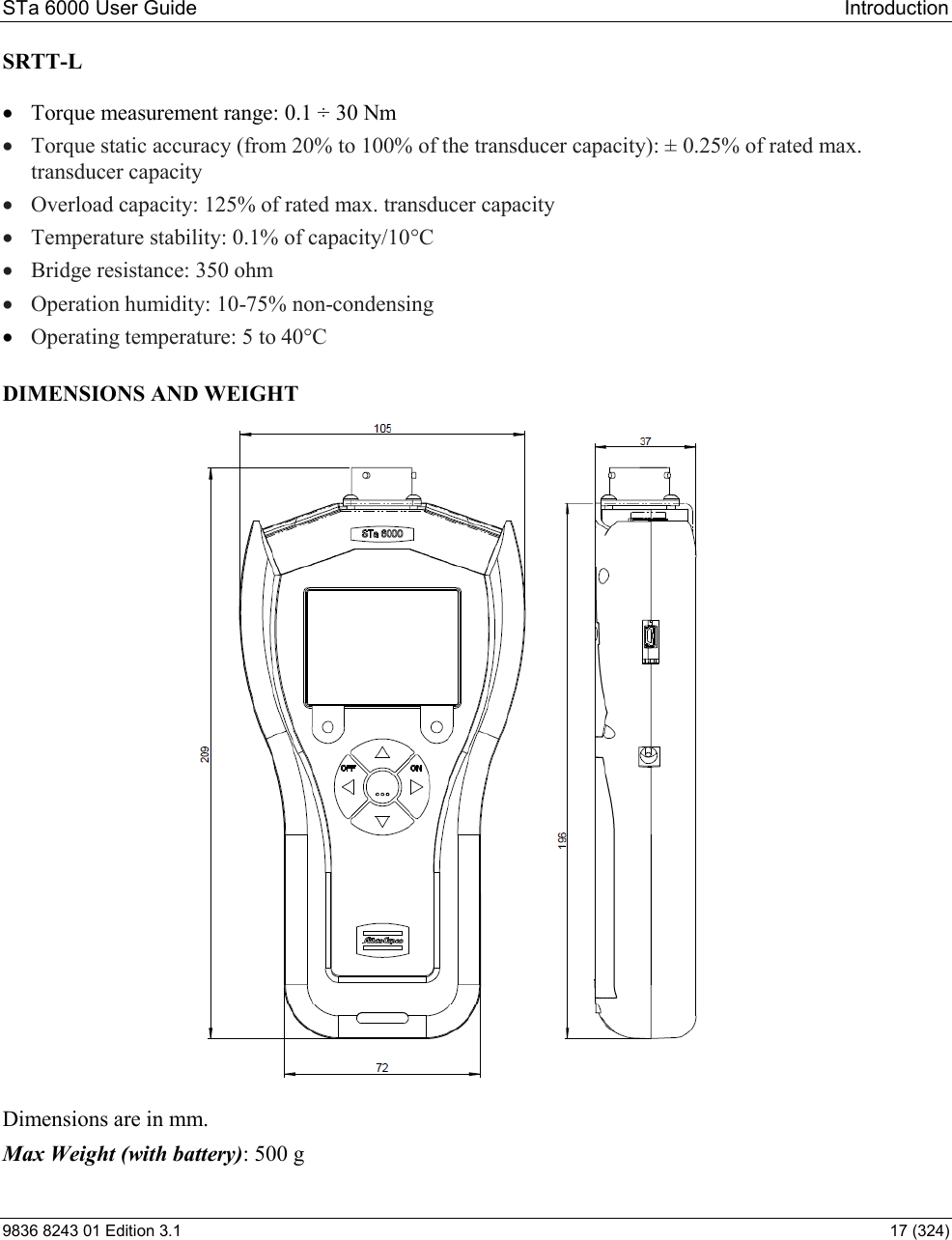
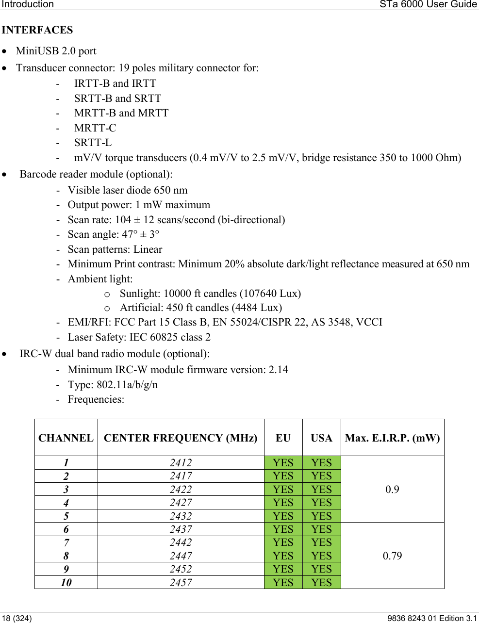
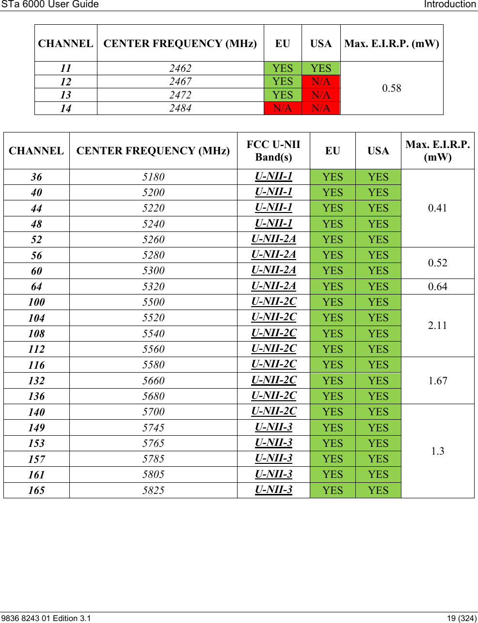
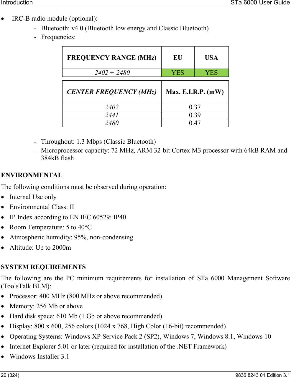
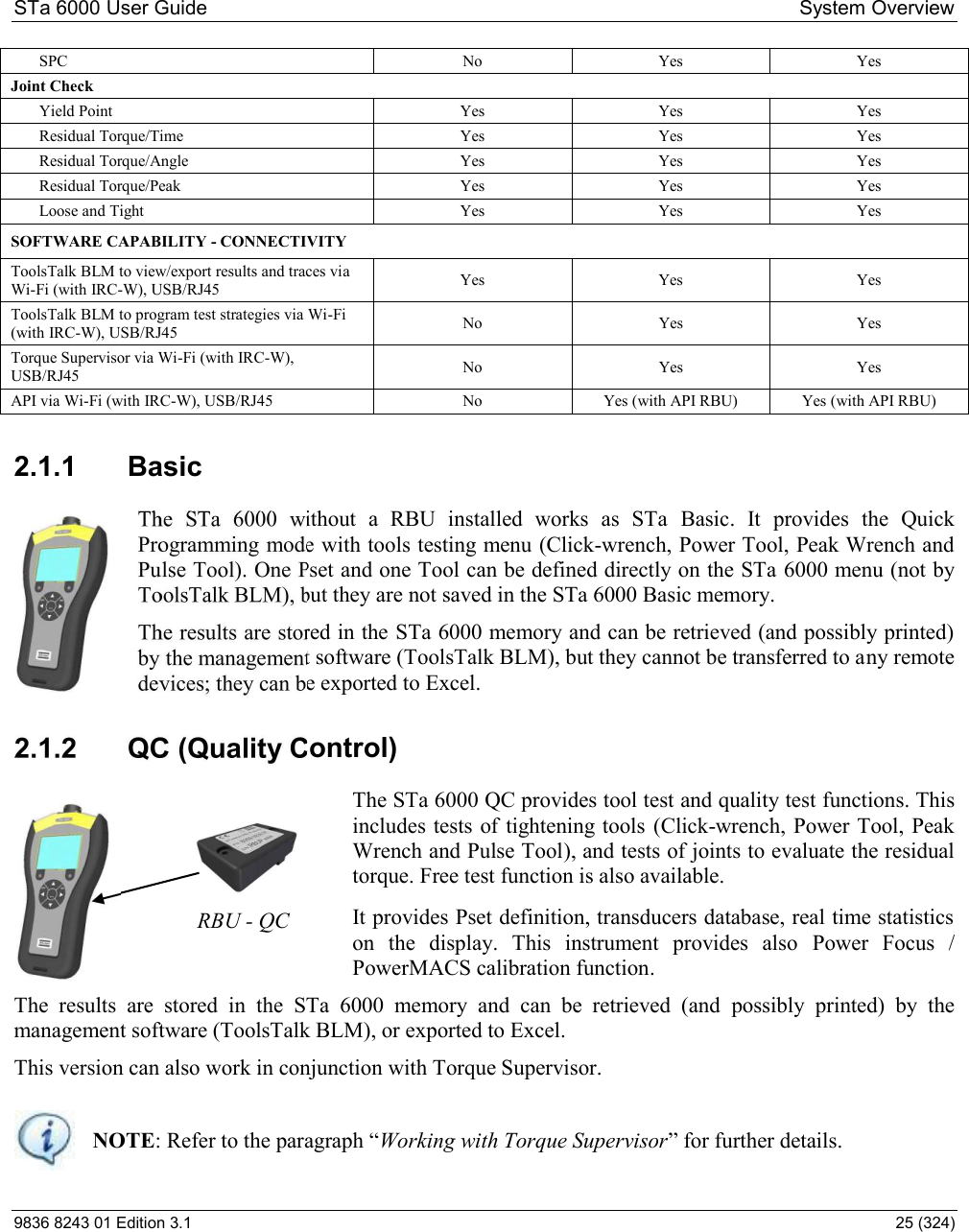
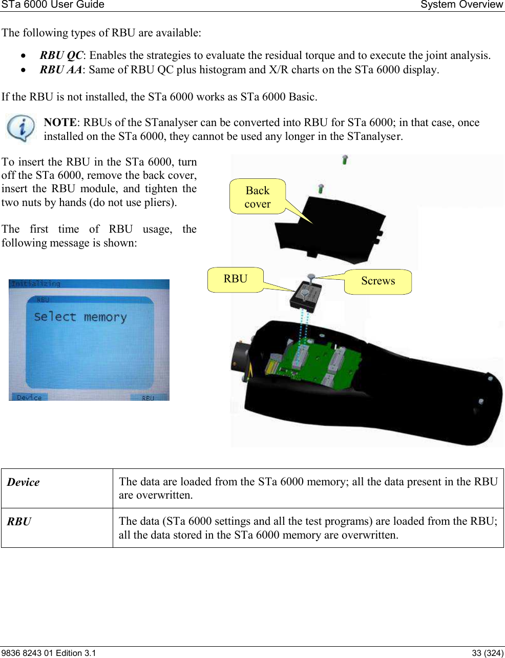
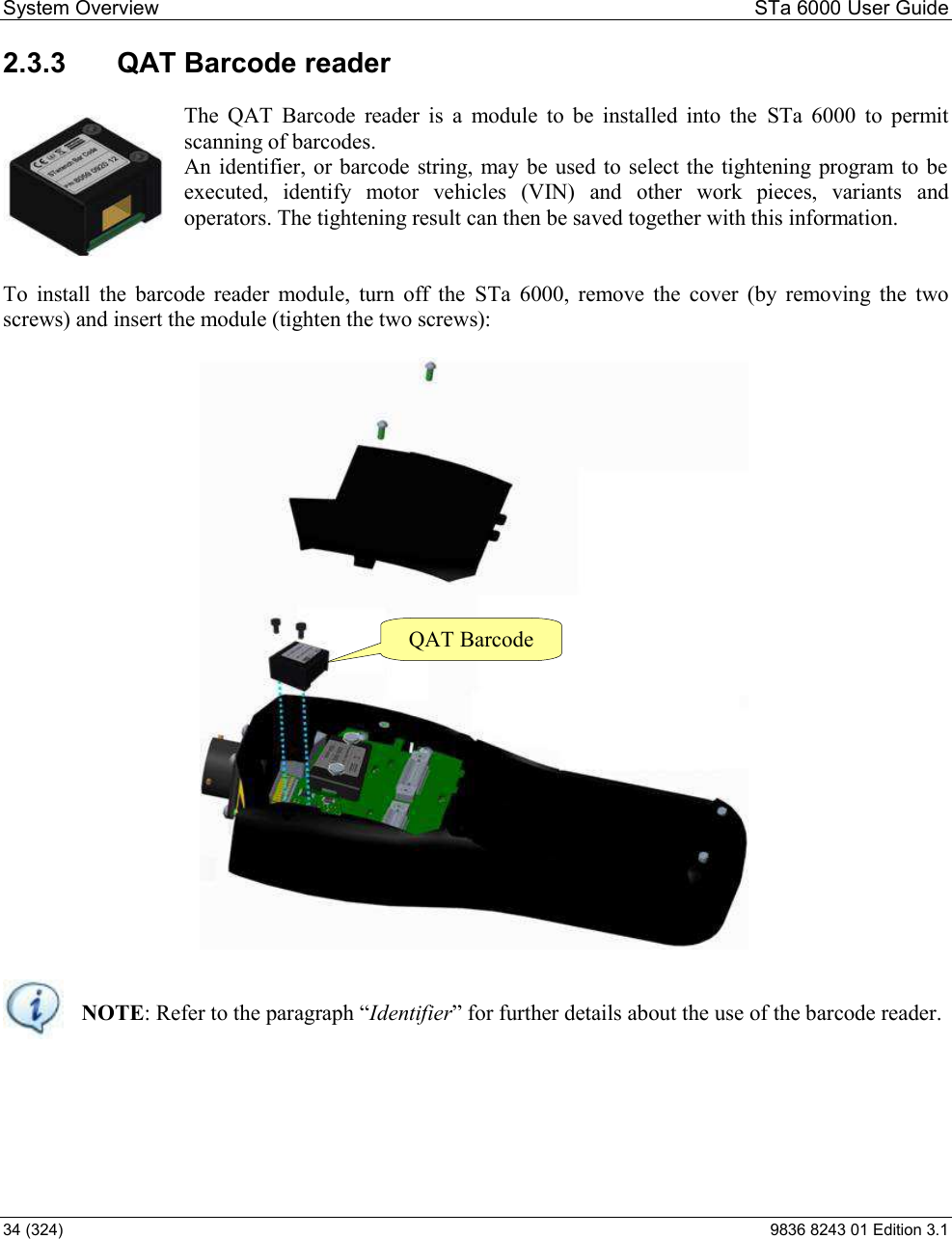
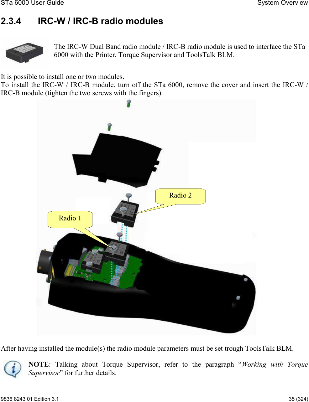
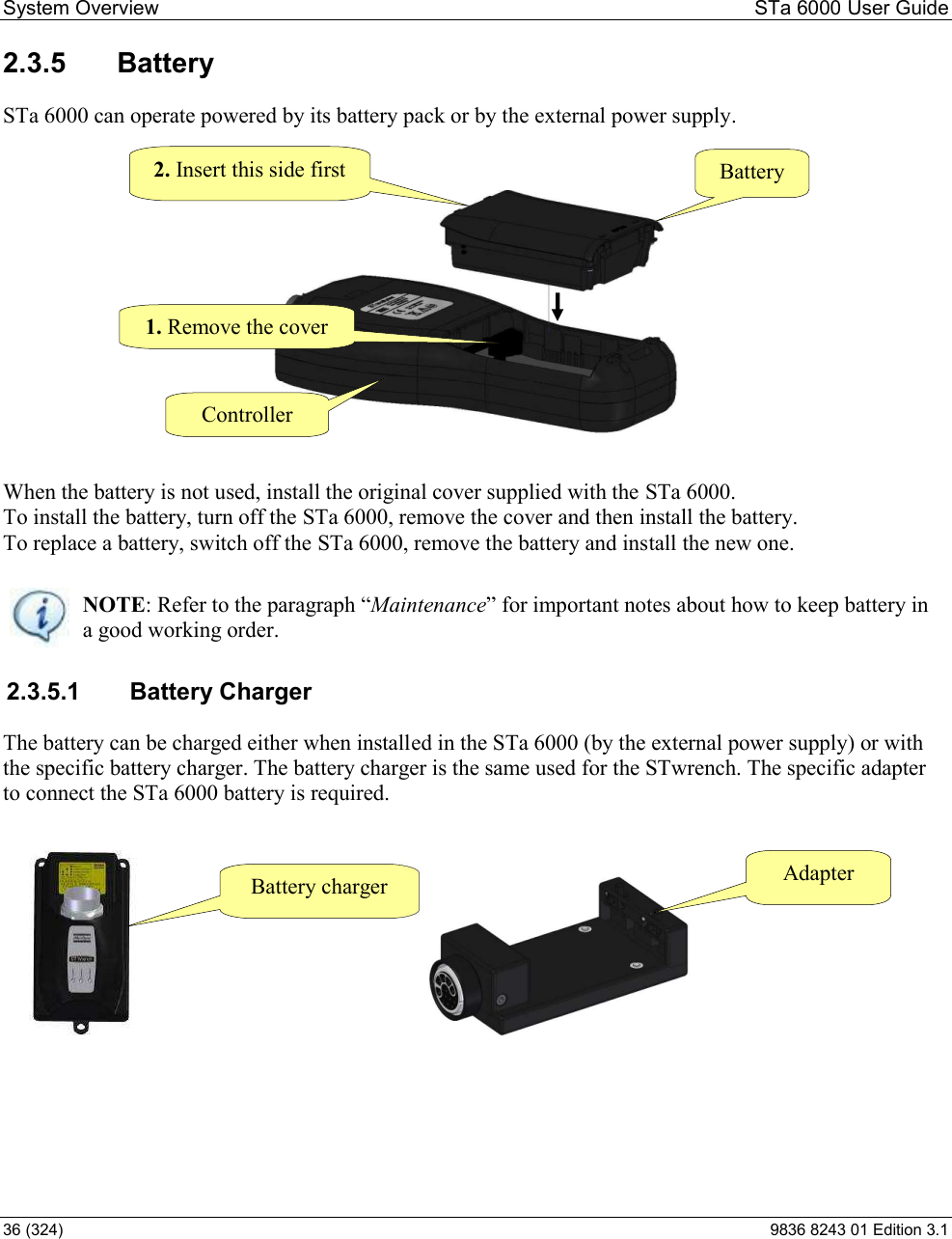
![System Overview STa 6000 User Guide 24 (324) 9836 8243 01 Edition 3.1 2.1 STa 6000 Versions This chapter provides an overview of the STa 6000 versions. The STa 6000 version is defined by the Rapid Backup Unit (RBU) installed: Basic (no RBU) QC AA RBU HARDWARE CAPABILITY Number of Channel 1 1 1 Torque Yes Yes Yes Angle (Encoder or Gyroscope) Yes Yes Yes MRTT-C connection for joint checks Yes Yes Yes Size in mm 110x200x45 110x200x45 110x200x45 Weight [grams] 500 500 500 Color Display Yes Yes Yes Keyboard Yes Yes Yes Result Storage 50000 50000 50000 Traces Storage 50000 50000 50000 RBU Rapid Backup Unit No Yes Yes Direct power Supply (slow charger 6H) Yes Yes Yes RJ45 (Ethernet) Yes Yes Yes USB Yes Yes Yes Non Atlas Copco analog transducer connection Yes Yes Yes SOFTWARE CAPABILITY - ONBOARD Languages Yes Yes Yes Multi-units Yes Yes Yes Pset 1 (not saved) 1000 1000 Batch Count Yes Yes Yes CW/CCW Yes Yes Yes Database - Tool No 1000 1000 Quick Programming Yes Yes Yes Power Focus and PowerMACS calibration No Yes Yes Traces on display No Yes Yes Advanced analysis graphs on display No No Yes Custom measurement screen No Yes Yes Wi-Fi print Yes (with IRC-W module) Yes (with IRC-W module) Yes (with IRC-W module) Ethernet print Yes Yes Yes SOFTWARE FUNCTIONALTIES - ONBOARD Tool Check Wrench testing Yes Yes Yes Power tool testing Yes Yes Yes Pulse Tool testing Yes Yes Yes Min, Max, Med, Sigma statistics Yes Yes Yes Cm/Cmk No Yes Yes](https://usermanual.wiki/Atlas-Copco-BLM/STA6K/User-Guide-3058703-Page-24.png)