Applied Wireless Identifications Group R26EA011 LR-911 and 2010AR RFID Reader User Manual MPR 2010AR Manual
Applied Wireless Identifications Group Inc. LR-911 and 2010AR RFID Reader MPR 2010AR Manual
UserManual.wiki
>
Applied Wireless Identifications Group
>
R26EA011 User Manual
>
Users Manual
Contents
1.
GMSW Holding Instructions
2.
LR911 Installation Instructions
3.
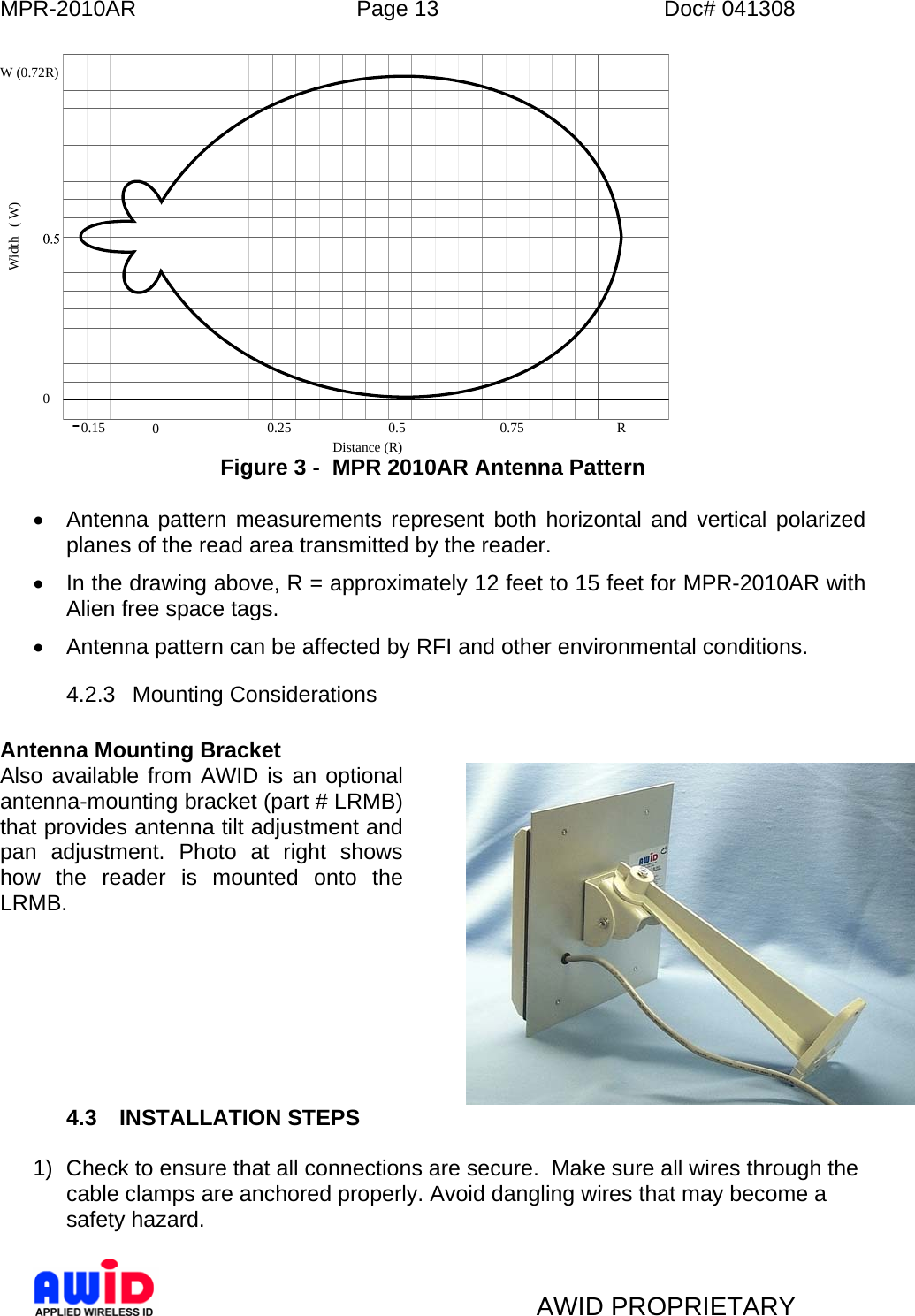
Users Manual
4.
Tag MT Mounting Recommendations
5.
Tag WS Mounting Recommendations
Users Manual
Navigation menu
Upload a User Manual
Namespaces
Wiki Guide
HTML
PDF
Info
Views
User Manual
Discussion / Help
Navigation