AnyDATA DTS-800CDK CDMA Development kit DTS-800 User Manual
AnyDATA Corporation CDMA Development kit DTS-800
UserManual.wiki
>
AnyDATA
>
DTS-800CDK User Manual
>
User Manual
Contents
1.
Service manual
2.
User Manual
User Manual
Navigation menu
Upload a User Manual
Namespaces
Wiki Guide
HTML
PDF
Info
Views
User Manual
Discussion / Help
Navigation
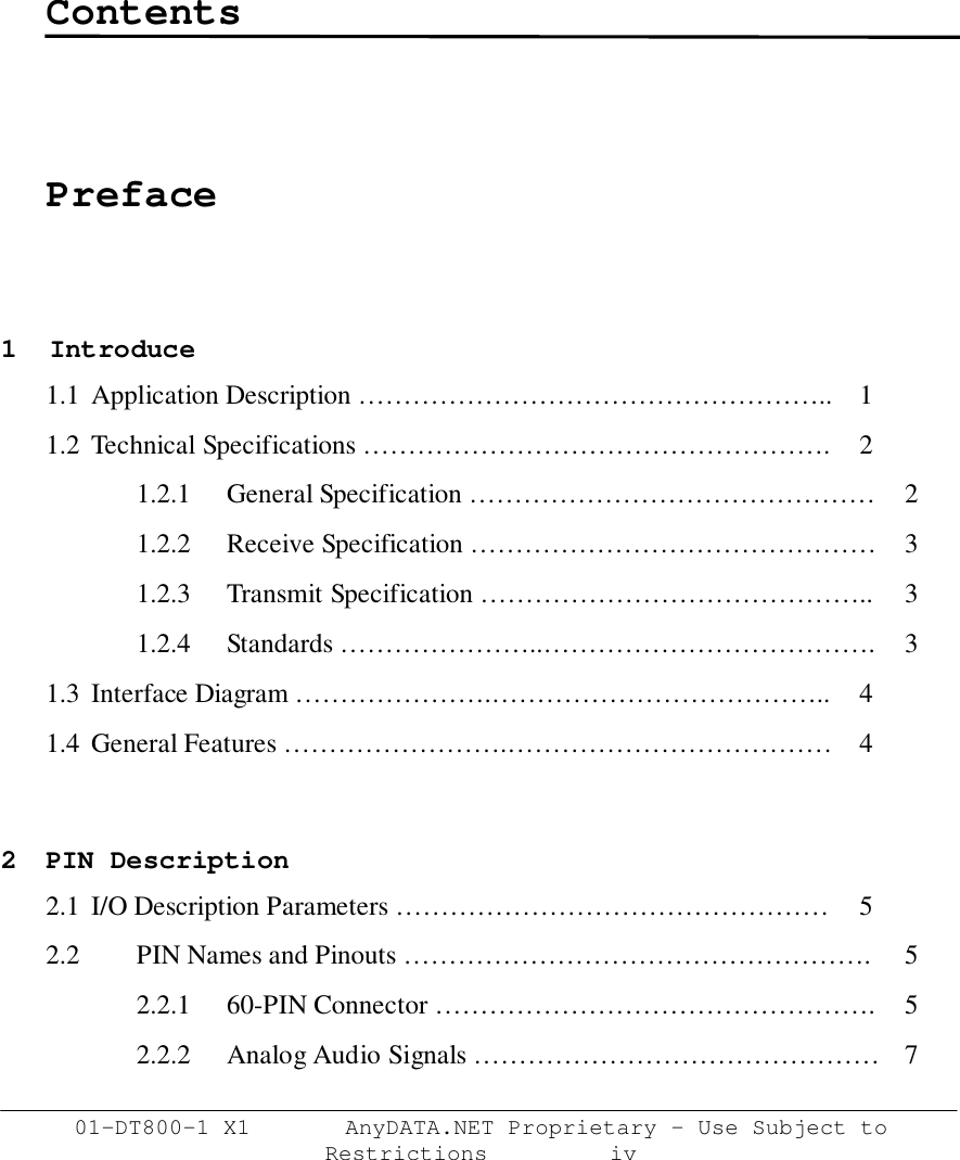
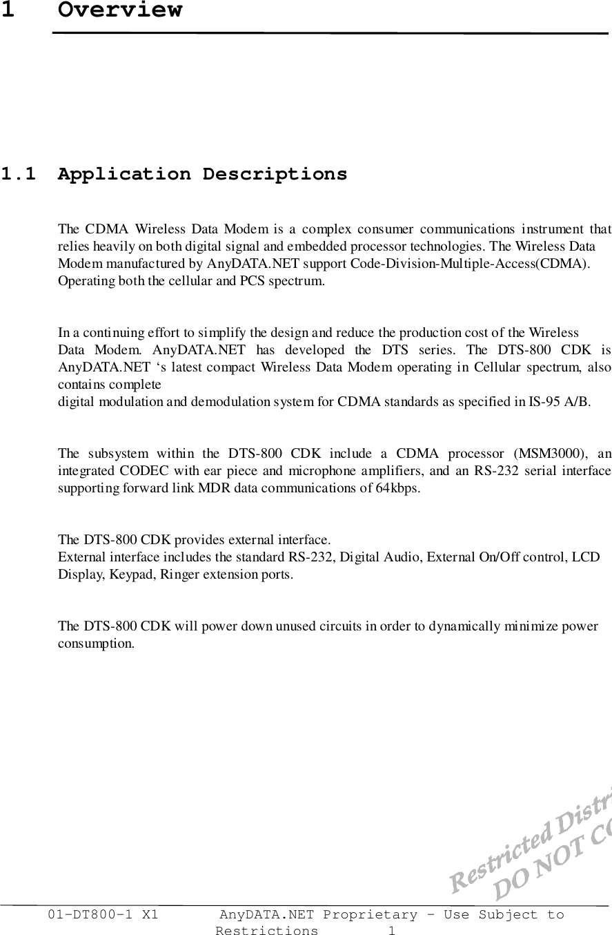
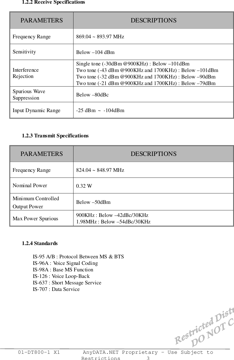
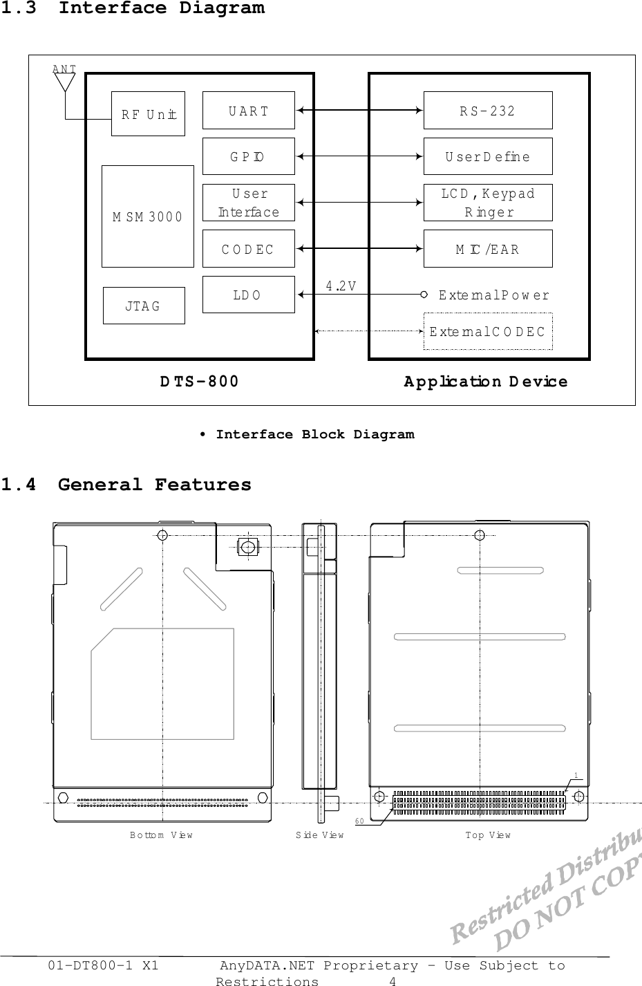
![Interface Description DTS-800 Reference Manual Application Information01-DTS800 CDK-1 X1 AnyDATA.NET Proprietary – Use Subject toRestrictions 143.5.1 Key PadThe key pad interface is consists of 4X5 matrix pattern. 5-KEYSENSE/[4:0] pins can beused to connect a matrix key pad to the modem. But all pins are not necessary, just4-KEYSENSE/ pins are used. KEYSENSE/ pins are active low.5-GPIO pins are necessary to make other side of matrix, 5-GPIO pins are must activehigh. The general key pad matrix are below :• Keypad Matrix3.5.2 LCDThe modem supports CLD interface. The LCD interface composed of 15-signals. #KEYSENSE0/KEYSENSE1/KEYSENSE2/KEYSENSE3/1-GPIO2-GPIO3-GPIO4-GPIO5-GPIO9630852*741SENDENDReserved](https://usermanual.wiki/AnyDATA/DTS-800CDK.User-Manual/User-Guide-221762-Page-21.png)
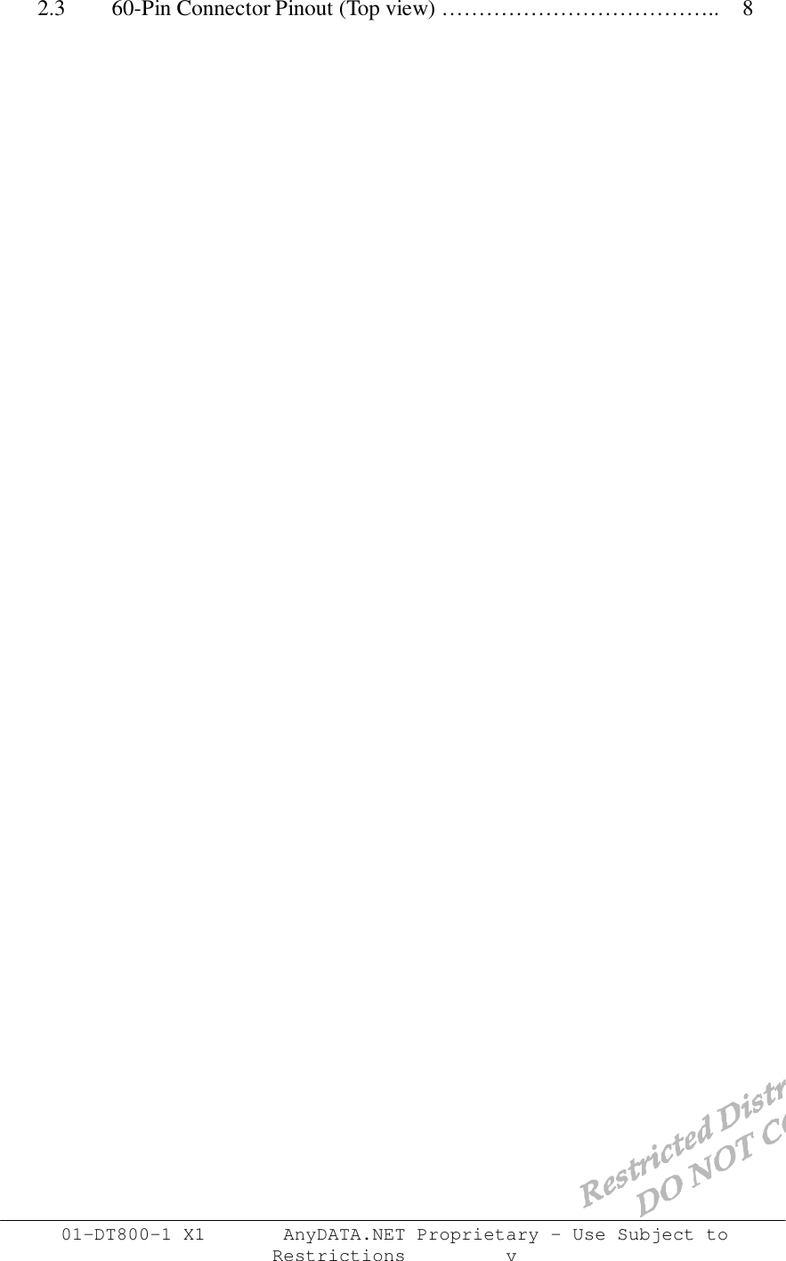
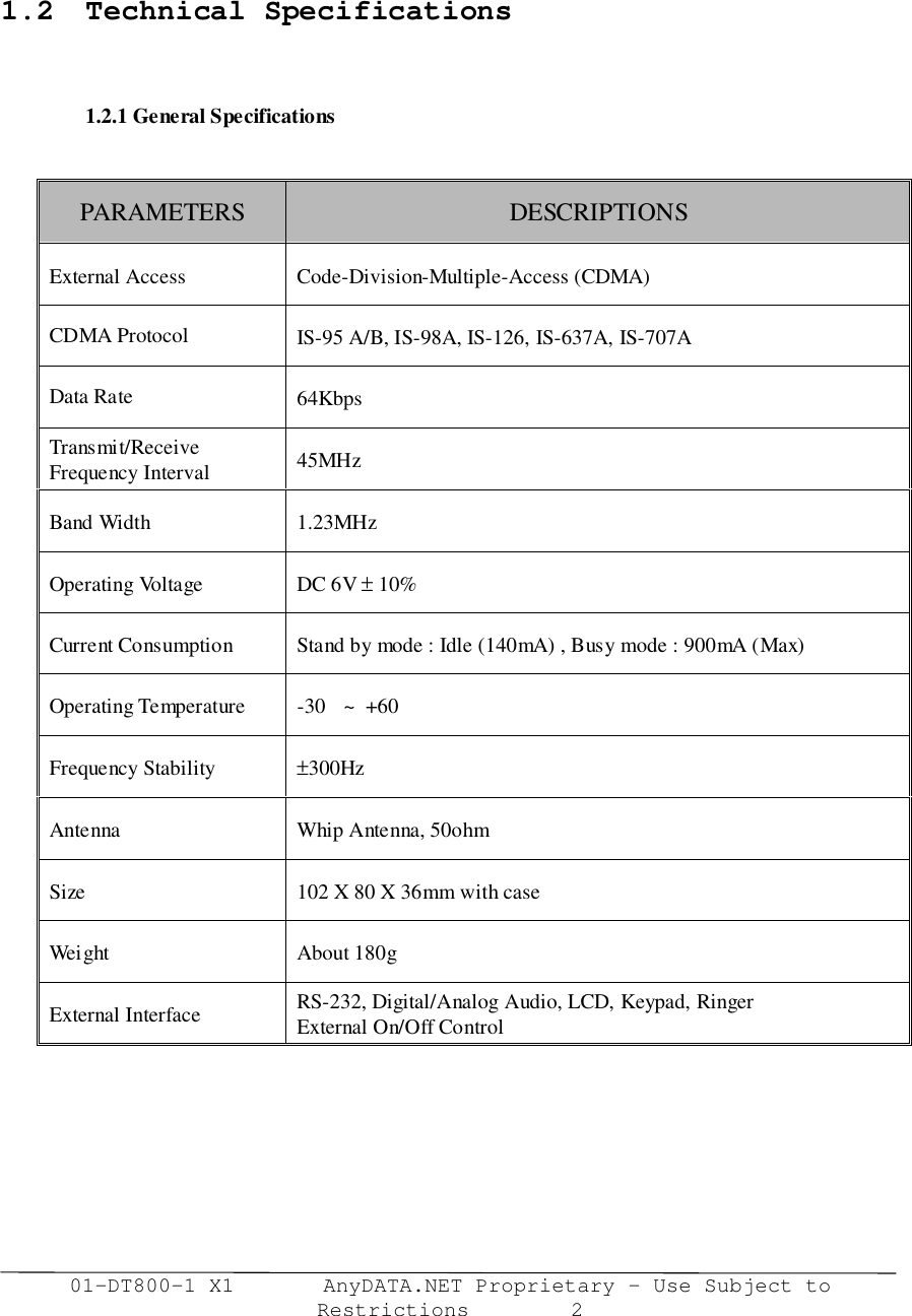
![Electrical Specifications DTS-800 Reference Manual Application Information01-DTS800 CDK-1 X1 AnyDATA.NET Proprietary – Use Subject toRestrictions 204.2.2 LCD Timing• LCD TimingPARAMETER DESCRIPTION MIN MAX UNITtLCDES LCD_CS/ active to LCD_E active nstLCDEHI Pulse width if LCD_E active nstLCDEH LCD_E inactive to LCD_CS/ inactive (write) nstLCDEHR LCD_E inactive to LCD_CS/ inactive (Read)tRDS Read data setup nstRDH Read data hold nstWRS Write data setup to LCD_E inactive nstWRH Write data hold from LCD_E inactive ns• LCD Timing Parameters; κ, Ι, ν ισ ιντεγερ λοωερ τηαν 16, ΜΧΛΚ ισ ιντερναλ Χλοχκ οφ µοδεµtWRSMCLK(m odem )A[21:0]LW R /Write D ata[7:0]LCD_CS/RD/LCD_ER eadD ata[7:0]TtWRHtLCDEStLCDEHItLCDEHtRDStRDHLCD Data W riteLCD Data Read](https://usermanual.wiki/AnyDATA/DTS-800CDK.User-Manual/User-Guide-221762-Page-27.png)