Andrew Wireless System U7885L17E19P ION-U Remote Unit for cellular systems User Manual
Andrew Wireless System ION-U Remote Unit for cellular systems
UserManual.wiki
>
Andrew Wireless System
>
U7885L17E19P User Manual
>
user manual
Contents
1.
Installation Instruction
2.
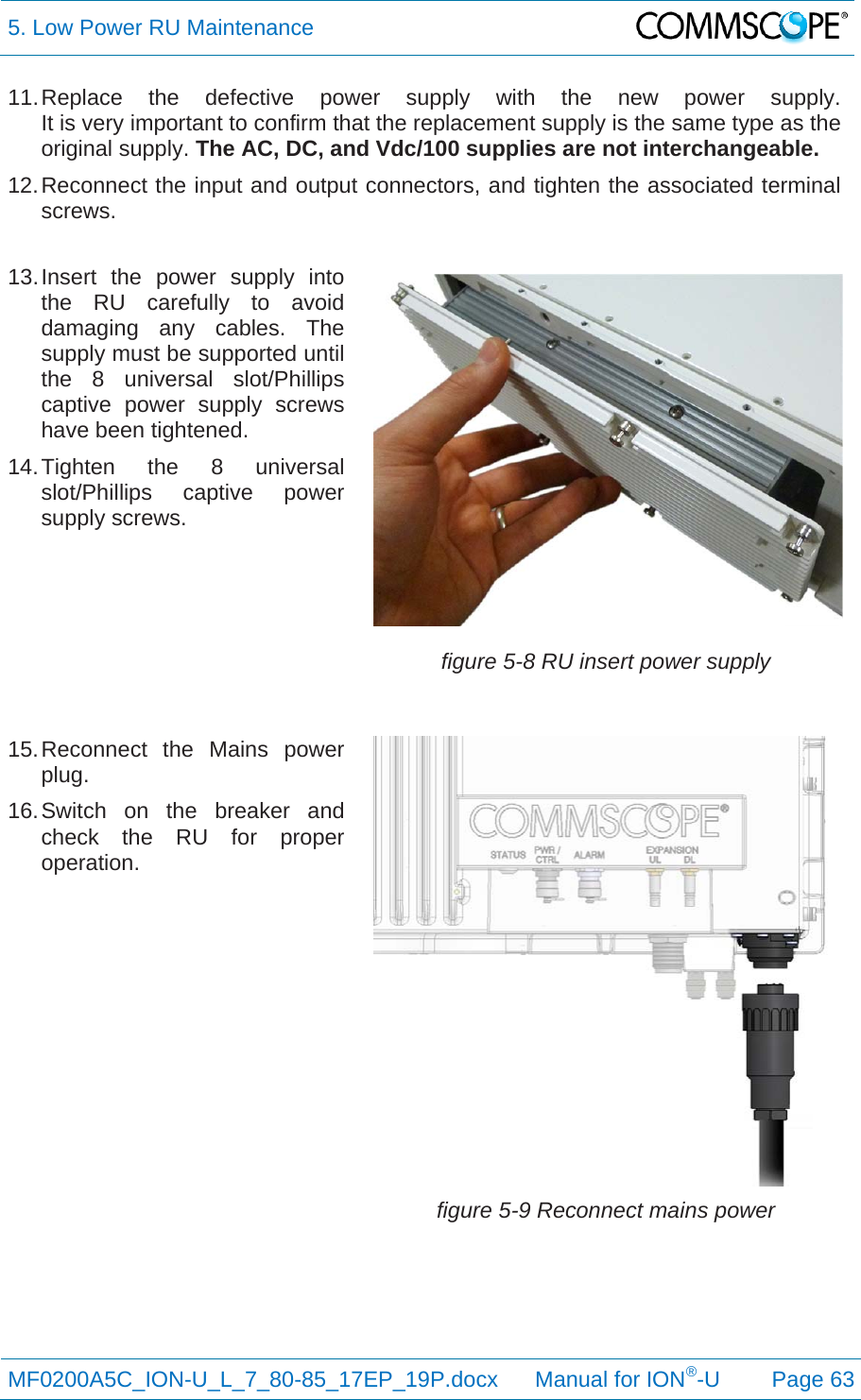
user manual
user manual
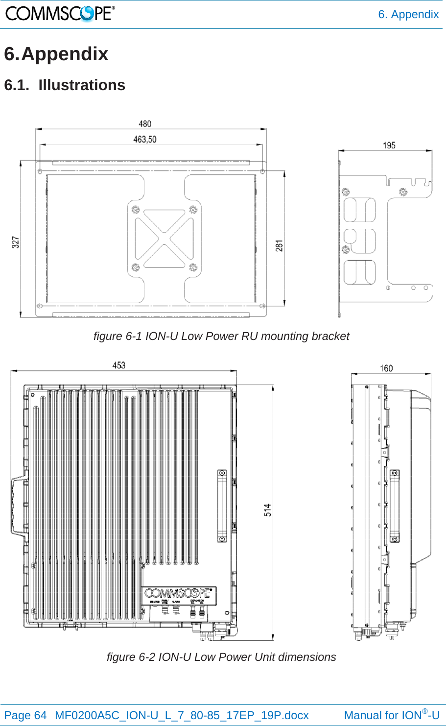
Navigation menu
Upload a User Manual
Namespaces
Wiki Guide
HTML
PDF
Info
Views
User Manual
Discussion / Help
Navigation
![1. General MF0200A5C_ION-U_L_7_80-85_17EP_19P.docx Manual for ION®-U Page 9 6. Notice: Keep operating instructions within easy reach and make them available to all users. 7. Notice: Read and obey all the warning labels attached to the unit. Make sure that all warning labels are kept in a legible condition. Replace any missing or damaged labels. 8. Notice: Only license holders for the respective frequency range are allowed to operate this unit. 9. Notice: Make sure the repeater settings are correct for the intended use (refer to the manufacturer product information) and regulatory requirements are met. Do not carry out any modifications or fit any spare parts, which are not sold or recommended by the manufacturer. 1.4. Compliance 1. Notice: For installations which have to comply with European EN50385 exposure compliance requirements, the following Power Density limits/guidelines (mW/cm²) according to ICNIRP are valid: o 0.2 for frequencies from 10 MHz to 400 MHz o F (MHz) / 2000 for frequencies from 400 MHz to 2 GHz o 1 for frequencies from 2 GHz to 300 GHz 2. Notice: For installations, which have to comply with FCC RF exposure requirements, the antenna selection and installation must be completed in a way to ensure compliance with those FCC requirements. Depending on the RF frequency, rated output power, antenna gain, and the loss between the repeater and antenna, the minimum distance D to be maintained between the antenna location and human beings is calculated according to this formula: ]/[][][24cmmWmWcmPDPD where P (mW) is the radiated power at the antenna, i.e. the max. rated repeater output power in addition to the antenna gain minus the loss between the repeater and the antenna. PD (mW/cm²) is the allowed Power Density limit acc. to 47 CFR 1.1310 (B) for general population / uncontrolled exposures which is o F (MHz) / 1500 for frequencies from 300MHz to 1500MHz o 1 for frequencies from 1500MHz to 100,000MHz RF exposure compliance may need to be addressed at the time of licensing, as required by the responsible FCC Bureau(s), including antenna co-location requirements of 1.1307(b)(3).](https://usermanual.wiki/Andrew-Wireless-System/U7885L17E19P.user-manual/User-Guide-3031569-Page-9.png)