Andrew Wireless Innovations Group BCP-TFAM26 Model TFAM26 Downlink Booster User Manual
Andrew Wireless Innovations Group Model TFAM26 Downlink Booster
Contents
- 1. Users manual part 1 of 3
- 2. Users manual part 2 of 3
- 3. Users manual part 3 of 3
Users manual part 3 of 3
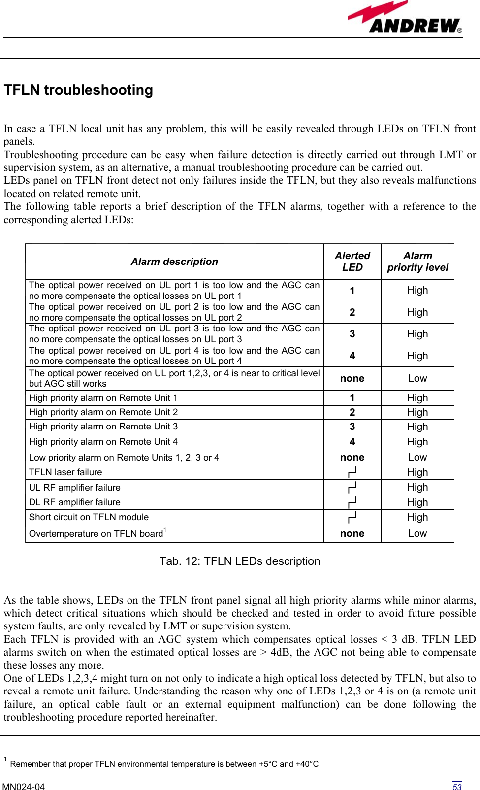
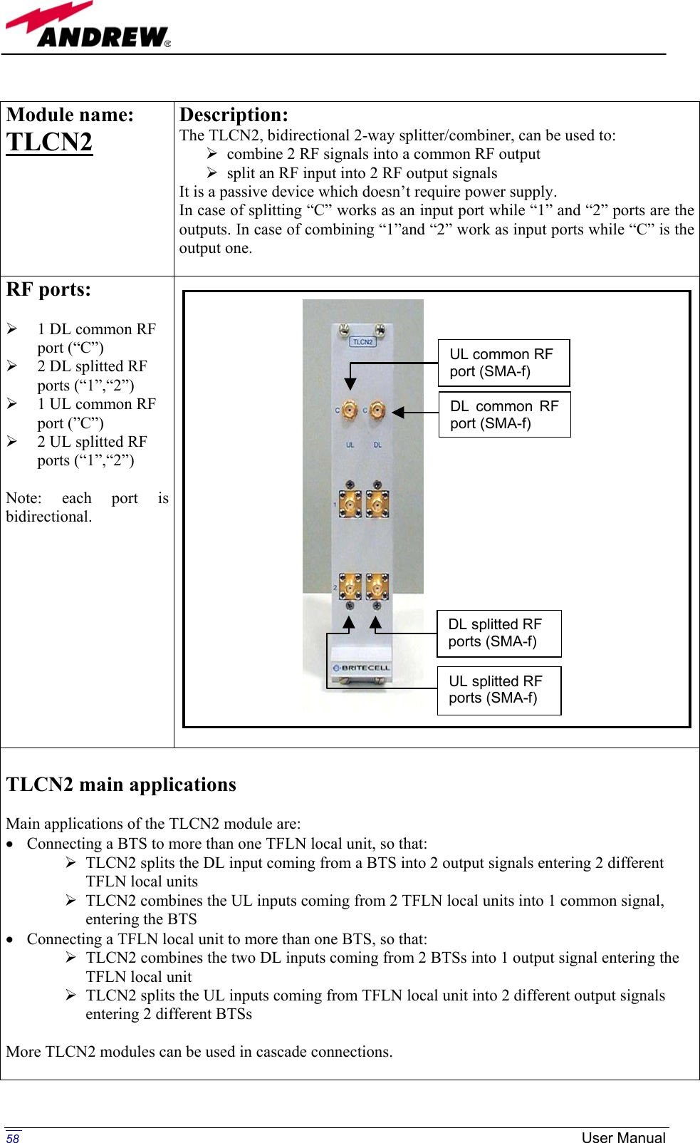
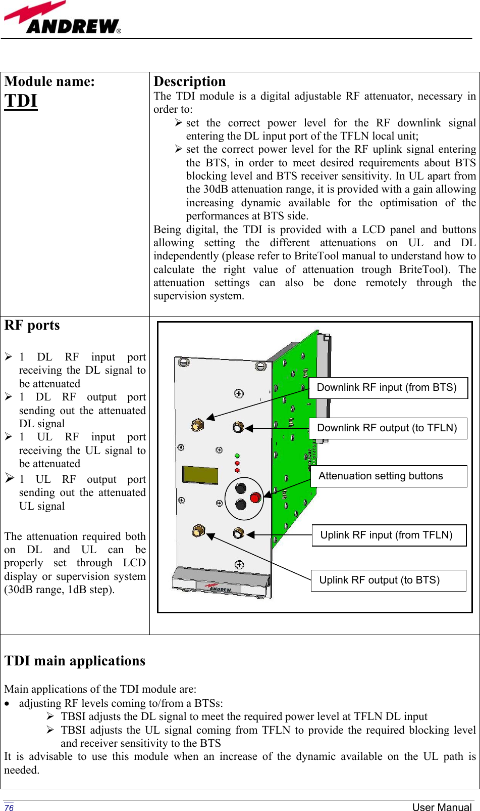
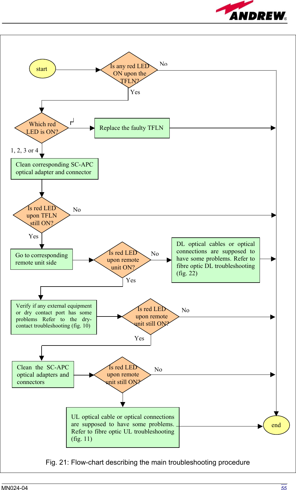
![Main troubleshooting procedure (The following procedure is summarized by the flow-chart in fig. 21) In case the TFLN general alarm (LED ┌┘) is on replace the faulty TFLN local unit with a new one and contact the manufacturer for assistance. In case one of the LEDs 1,2,3,4 is on the corresponding TFLN adapter might be dirty. Try cleaning it using pure ethyl alcohol. If the LED is still on go to the corresponding remote unit side and check the red LED upon TFAxxx warm side: If it is off, the optical cables or the optical connections are supposed to have some problem on DL path. Refer to fibre optic DL troubleshooting for more information (fig. 22). If it is on, refer to dry-contact troubleshooting (fig. 10) to understand whether the alarm can depend on external equipment failure or not. In case dry-contact troubleshooting does not reveal any failure, clean the remote unit optical adapters. If the problem still persists the UL optical cable or optical connections is supposed to have some problems. Please refer to the fibre optic UL troubleshooting (fig. 11) for more information. Fibre optic DL troubleshooting (The following procedure is summarized by the flow-chart in fig. 22) Check if there is any point where fibre experiences a short radius of curvature. In this case, rearrange the optical path in order to avoid sharp bends (if necessary, replace the optical cable with a longer one). If TFLN red LED switches off, troubleshooting has been successfully carried out. Otherwise, follow next steps. Check if SC-APC connectors are properly installed at both fibre ends. In case they are not, fix better SC-SPC connectors to adapters. If TFLN red LED switches off, troubleshooting has been successful. Otherwise, follow next steps. Disconnect the optical fibre and clean it better at both ends then clean the SC-APC ports on both the TFLN and the remote unit. Re-connect the fibre to relevant ports after cleaning. If it doesn’t made TFLN red LED switch off, follow next steps. Disconnect the optical SC-APC connector from remote unit DL port, and measure the output power Pout(DL) at the corresponding fibre end. Then, go to the TFLN side, disconnect the optical SC-APC connector from TFLN DL port and measure the input power Pin(DL) coming out of the TFLN DL port. Calculate the DL fibre attenuation ADL as ADL [dB] = P in(DL) - P out(DL) If ADL > 4dB, then the fibre optic cable has some problems. Replace it with a new one. If ADL < 4dB troubleshooting procedure has not identified the problem. Refer to supervision system or contact assistance. 54 User Manual](https://usermanual.wiki/Andrew-Wireless-Innovations-Group/BCP-TFAM26.Users-manual-part-3-of-3/User-Guide-444070-Page-4.png)
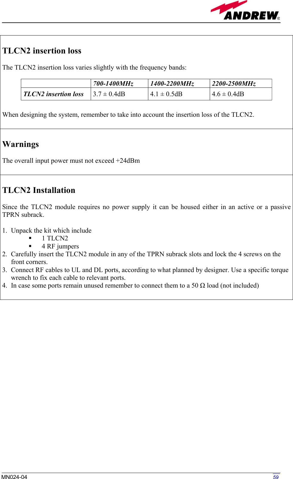
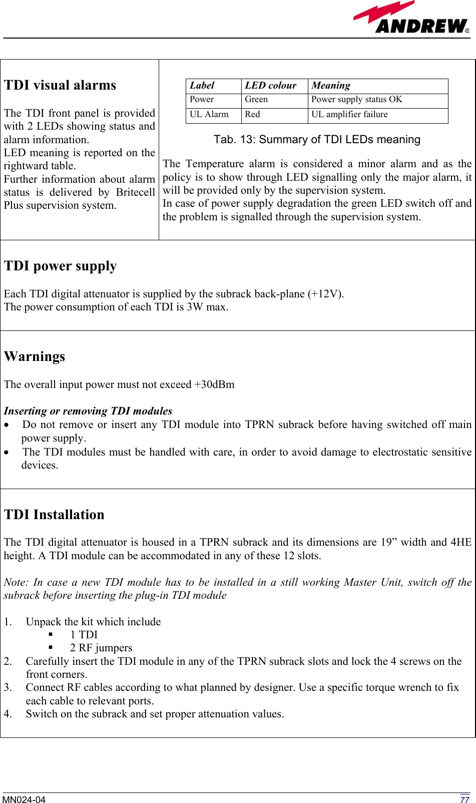
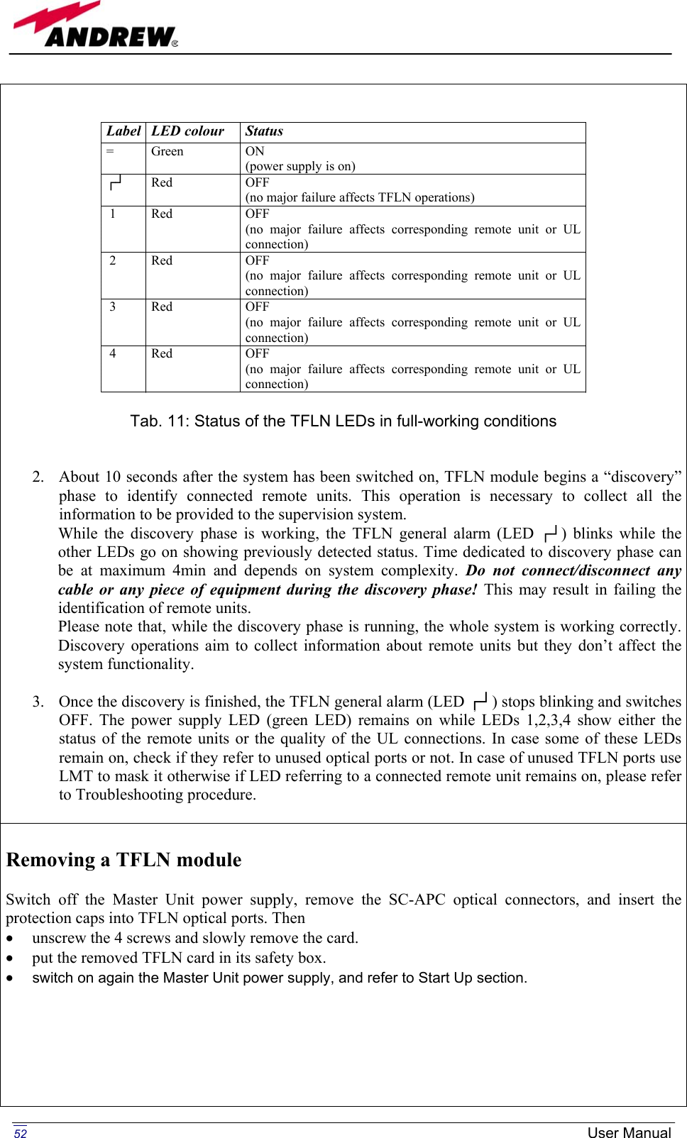
![Go to TFLNside. Is red LED upon remote unit still ON? Is red LED upon remote unit still ON?YesNo YesNo end Troubleshooting procedure hasnot identified the problem. Referto supervision system or contactassistance Fibre optic cable has someproblems. Replace it. Is ADL > 4dB? Calculate DL fibre attenuation ADL[dB]=input power - output power Disconnect optical SC-APCconnector from TFLN DLport. Measure the input powercoming out of the TFLNDL port. Measure the output powerat corresponding fibre end.Reconnect the fibre to relevant ports Disconnect fibre opticand clean it at both ends.Clean optical SC-APCports on both TFLNand remote unit.Disconnect the opticalSC-APC connector fromremote unit DL port YesNo YesNoYesNo No YesFix better SC-APCconnectors Are SC-APC connectors properly installed at both fibre ends? Is red LED upon remote unit still ON? Rearrange the optical path to avoid sharp bends. If necessary replace the optical cable with a longer one. Is there any point where the fibre experiences a small radius of curvature? start Fig. 22: Flow-chart describing the fibre optic DL troubleshooting 56 User Manual](https://usermanual.wiki/Andrew-Wireless-Innovations-Group/BCP-TFAM26.Users-manual-part-3-of-3/User-Guide-444070-Page-6.png)