Andante Medical Devices SMARTSTEP0106 Bluetooth Transmitter User Manual 2
Andante Medical Devices Ltd. Bluetooth Transmitter 2
UserManual.wiki
>
Andante Medical Devices
>
SMARTSTEP0106 User Manual
>
User Manual 2
Contents
1.
User Manual 1
2.
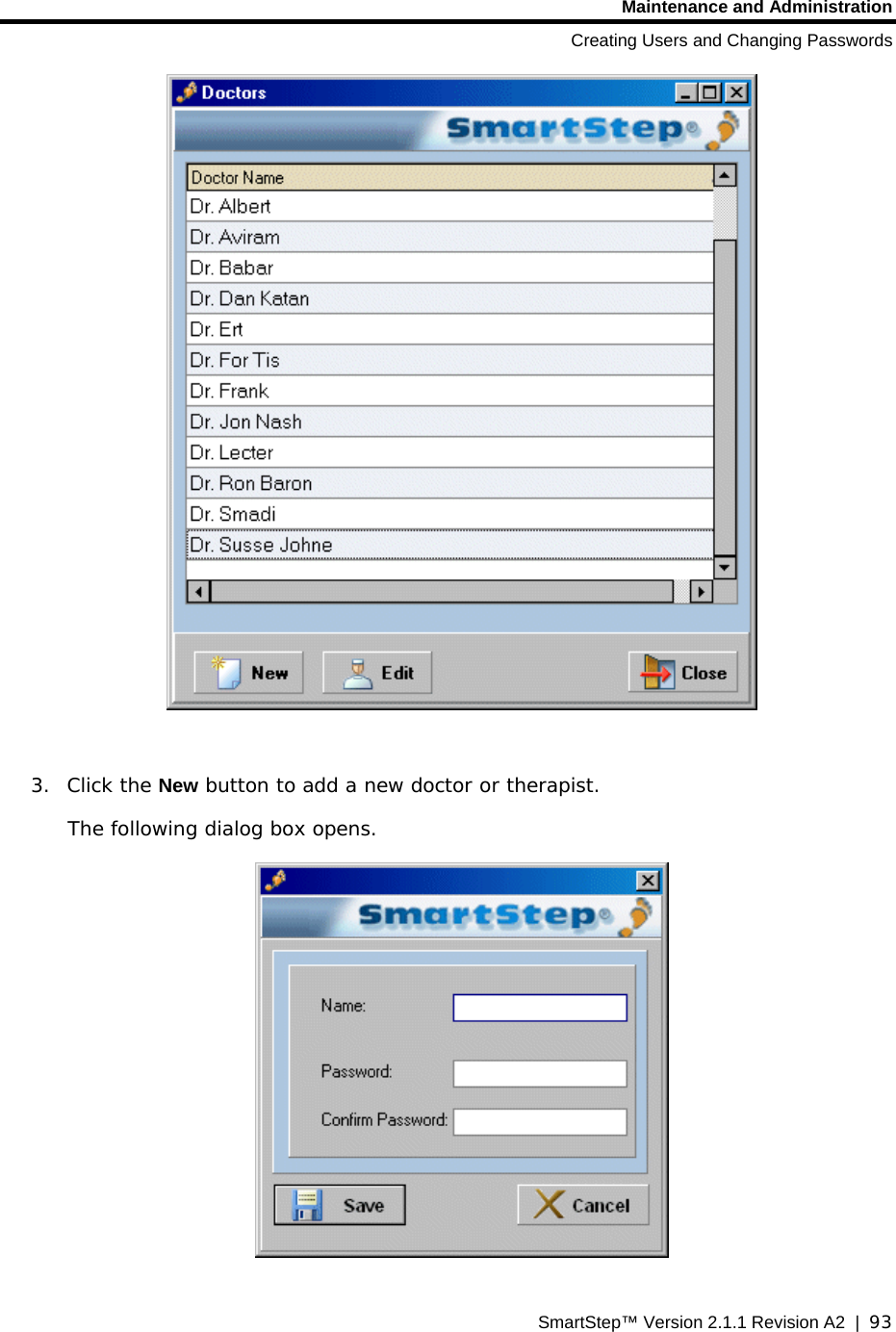
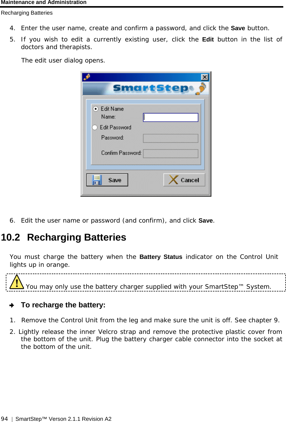
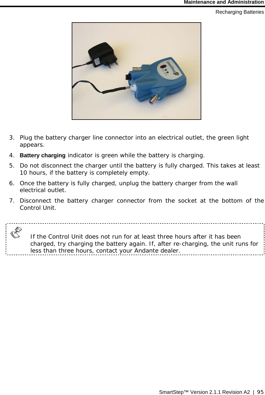
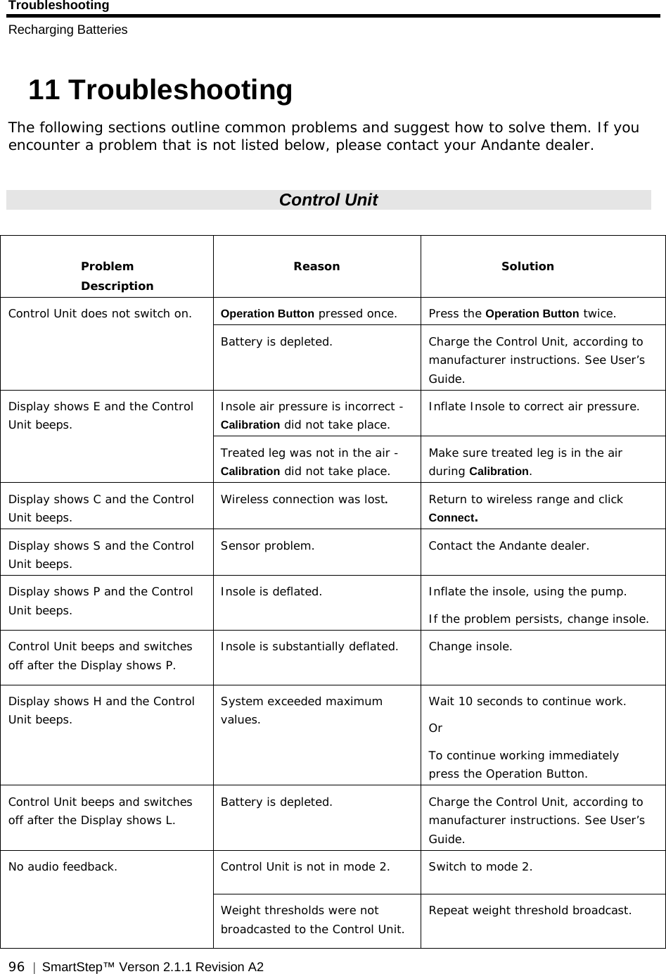
User Manual 2
User Manual 2
Navigation menu
Upload a User Manual
Namespaces
Wiki Guide
HTML
PDF
Info
Views
User Manual
Discussion / Help
Navigation