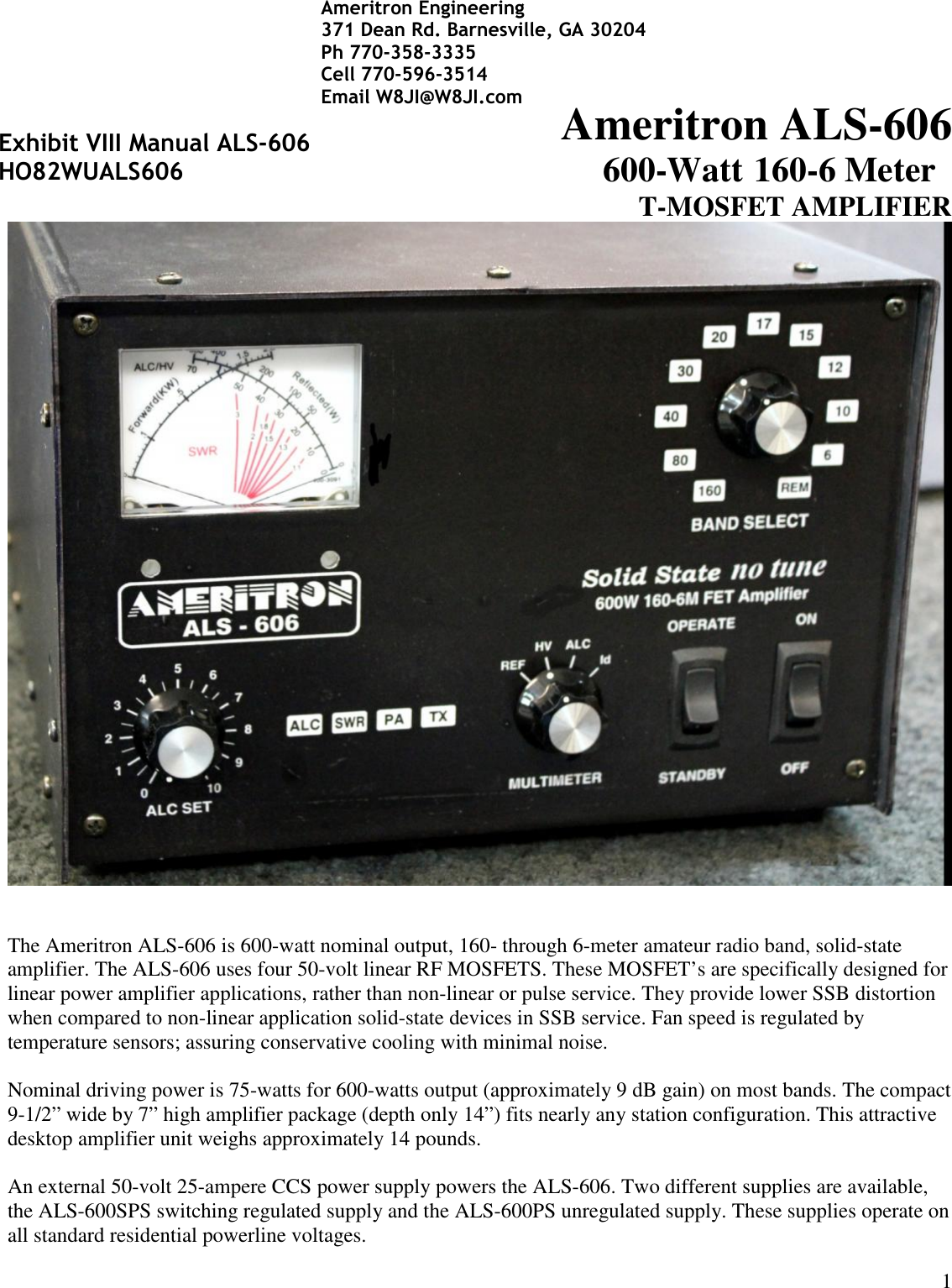
Ameritron 2WUALS606 Amateur Radio Amplifier User Manual Manual

Ameritron Amateur Radio Amplifier Manual

Manual

1Ameritron ALS-606600-Watt 160-6 MeterT-MOSFET AMPLIFIERThe Ameritron ALS-606 is 600-watt nominal output, 160- through 6-meter amateur radio band, solid-stateamplifier. The ALS-606 uses four 50-volt linear RF MOSFETS. These MOSFET’s are specifically designed forlinear power amplifier applications, rather than non-linear or pulse service. They provide lower SSB distortionwhen compared to non-linear application solid-state devices in SSB service. Fan speed is regulated bytemperature sensors; assuring conservative cooling with minimal noise.Nominal driving power is 75-watts for 600-watts output (approximately 9 dB gain) on most bands. The compact9-1/2” wide by 7” high amplifier package (depth only 14”) fits nearly any station configuration. This attractivedesktop amplifier unit weighs approximately 14 pounds.An external 50-volt 25-ampere CCS power supply powers the ALS-606. Two different supplies are available,the ALS-600SPS switching regulated supply and the ALS-600PS unregulated supply. These supplies operate onall standard residential powerline voltages.Exhibit VIII Manual ALS-606HO82WUALS606Ameritron Engineering371 Dean Rd. Barnesville, GA 30204Ph 770-358-3335Cell 770-596-3514Email W8JI@W8JI.com
2Quick StartThank you for purchasing this amplifier system.The ALS606 is a compact 600-watt nominal PEP output amplifier. It uses an external power supply system.This amplifier covers 160-6 meters. Nominal drive power is 75-watts or less. NOTE: This amplifier excludesall operation between 25 and 28 MHz.The ALS606 interfaces with most modern amateur radio transceivers. Supported band data input includesICOM compatible analog voltage, Elecraft and Yaesu BCD band data, and Kenwood serial data. With properinterface cables and data, this amplifier will automatically change bands in step with transceiver band changes.Automatic band selection using a band data port or band decoded bus requires purchasing an Ameritroninterface cable for your radio.Carefully unpack this amplifier and power supply. Please inspect everything for physical shipping damage; thisincludes cabinets and chassis. Ameritron does not package dented or damaged units. Cabinets and controls canbe broken, bent, or dented with rough handling. If a new unit arrives mechanically damaged, including brokenknobs or switches, it is always from handling somewhere between Ameritron and the end user. In the event ofcabinet damage or broken controls, please contact the dealer immediately. To permit claim processing, retain allboxes and packing materials.Installation and OperationWARNING: Do not block ventilation holes. Do not expose to moisture, water, or external heat.This power amplifier system consists of two units, a power supply and an amplifier section. The amplifiersection has metering and operator functional controls. Locate the amplifier section at a convenient place withproper space for airflow, within the operator’s reach and view. The power supply can be placed anywherewithin cable length limits. Do not extend the amplifier power supply dc power cable.Power Line or Mains ConnectionsThere are two distinctly different power supplies available for the ALS-606. The ALS-600PS is more basicunregulated choke input supply. The ALS-600SPS is a state-of-the-art regulated switching mode supply. Pleaseread the appropriate sections below.  For non-export use, each supply comes with a standard NEMA 5-15P two-blade 120V 15A plug with round safety-ground pin.Overall amplifier operation remains similar with either supply; except the linear supply has a RTTY andNormal voltage switch. The RTTY position allows higher amplifier efficiency at reduced power. See the powersupply details included with the particular power supply for details specific to each supply. This includesoperation on various line voltages, power supply operation, fuse selection, location, and power supply troubleshooting.Non-export versions of Ameritron ALS-600 series power supplies are wired and fused for 120Vac USA powermains, but all are modifiable to other standard power mains voltages.
3ALS-600SPS1.) The USA standard version ALS-600SPS is supplied wired for 95-135 Vac, 50-400 Hz, 15-ampere orlarger electrical service. Reconfiguring internal jumpers on the power supply board will allow 185-260volt operation.2.) The ALS-600SPS is internally regulated. Beyond 120 or 240V concerns, the ALS-600SPS does notrequire voltage tap changes. There should be very little change in HV1 (PA voltage) with amplifierpower and line voltage. Less than 3 volts change from the 50Vdc nominal voltage is acceptable3.) Do not operate with line voltage below 95 or above 135 volts (185-260 volts when wired for “240volts”).4.) Unless power mains fall below 100 volts, the ALS600SPS switching supply provides the sameperformance on 120-volts as on 240-volts. The only function reasons for 240-volt power mains are lightdimming and unintentional line breaker opening. If outlet wiring is already loaded heavily, or if housewiring is sized too small for the distance to the mains supply, you may have to use a dedicated 120-Vamplifier line, or rewire the supply and use 240-volt mains5.) With 120Vac mains at 600-watt nominal RF output, current draw is approximately 12 amperes on steadycarrier. Peak line current is typically much less than 8 amperes at 600 watts PEP on SSB voice6.) The ALS-600SPS can be located anywhere, within reach of interfacing cables, convenient to youroperating setup. The location must be dry, airflow must not be restricted, and outside temperature mustnot be over 120F (49C). You must not extend or shorten the amplifier to power supply cable7.) Exceeding safe power supply load current forces the switch mode supply into shutdown. Restoreoperation by turning the main power switch off for a brief time. If the power supply detects a permanentoverload or the supply has failed, the supply will not resetALS-600PSThe ALS600PS uses a standard transformer with choke input filter system. It weighs significantly more thanthe ALS-600SPS, and is not voltage regulated.1.) The ALS600PS requires a 100-130 Vac, 50-60 Hz, 15-ampere or larger mains supply. This supply isreconfigurable for 210-250 volts by moving internal jumpers. The line cord uses a standard USA NEMA5-15P two-wire male plug with safety ground2.) This supply is unregulated. Voltage range includes all typical residential power line voltages, but theinternal buck-boost winding must be reconfigured if output voltage is more than 58 volts no load.Operation with no load voltages over 58 volts can compromise FET reliability3.) With 120Vac mains, current draw with steady 600-watt carrier is typically around 12 amperes. Linecurrent is typically less than 8 amperes at 600 watts PEP SSB voice.4.) The ALS600PS normally provides the same performance at 120-volts as at 240-volts, unless the powermains have excessive voltage drop. If you experience light dimming or line breaker opening, move thesupply to a dedicated 120-V line, or reconfigure the supply for, and use, 240-volts5.) This supply does not have overload protection, other than standard fuses
4Radio and Antenna ConnectionsWARNING: Forcing connector engagement can result in permanent connector damage. Solder on theoutside of center pins or bent pins are primary causes of female connector damage. External solder or bentcenter pins can permanently damage the female.Do not use Line Isolators on amplifier RF cables. The chassis of the amplifier should be at the same RFpotential as all other desk equipment. Shield isolators allow equipment to float to different RF chassispotentials. Different chassis potentials are exactly what we do not want, and isolators on desk coaxial cablesencourage differing enclosure RF voltages. It is better to cure RF problems outside the operating position.1.) RF connections are through standard UHF female connectors. Use 50-ohm coaxial cables with quality,properly soldered, UHF male (PL259) connectors. The output cable must safely handle at least 600watts2.) Examine the RF connectors. Female SO-239 UHF connectors have notches on the outer threaded-areaedge. PL259 UHF males have protruding tabs on the metal outside the center-pin insulator. These tabsand notches prevent unwanted connector rotation. The male tab or tabs must align and fit into femalenotches. This interlocking prevents connector rotation. It is best achieved by slightly wiggling orrotating the cable while hand-tightening the male’s shell to seat the male tab in the female notch.3.) With a firm handgrip, while making sure the PL259 male connector tab interlocks with the amplifier’sSO239 chassis connector notch, gradually tighten RF connectors. Do not use excessive force onconnectors. Check for proper tightness and seating by wiggling and flexing the cable and watching forany male connector movement on the female. Properly seated, connectors will be solidly locked withoutuse of pliers or tools4.) ALC and Relay (keying or TR line) connectors are standard phono females. Phono males from externalcables should push directly in with a snug, but not overly tight, fit5.) The Relay line operates with low voltage (<12V) and low current (<20 mA). Transmit is enabled bypulling the Relay line to ground with a relay contact or transistor. Read your radio manual. Unless youhave a very unusual radio, your radio should directly key this amplifier. Avoid using external interfaceswith relays. Amplifier relay switching time is approximately 10-12 mS6.) The remote and radio band data connectors are specialized connections. They are for use with Ameritronsupplied cables only
5OperationBefore attempting operation:1.) This amplifier is optimized for 50-ohm loads. Be sure your antenna system 50-ohm SWR is aslow as possible. As SWR increases from 1:1, either heat or distortion will increase2.) Be sure your antenna system, including any switches, baluns, matching circuits, or lightingprotection devices, are in good condition and will safely handle high power3.) Connectors, cables, and antennas must not have loose connections or insulation failure issues4.) Your exciter must be adjustable to significantly less than 100-watts output. Start at 50 wattsmaximum drive power and increase or decrease drive to reach desired power. Do not exceed 25amperes or 600 watts, and do not drive into non-linearity on SSB. A trapezoid scope pattern isrecommended for drive adjustment. Overdriving results in an excessively wide signal, andoverdriving can damage the amplifier5.) Power mains should be reasonably stable and match power supply voltage wiring6.) The low pass filters cut off just above the traditional primary amateur bands. A primary band’sfilter is used on the next lower WARC band. For example, the 20-meter low pass filter is usedon 30 meters. Some radios do not supply enough band data to know the exact band. With theseradios, amplifier band data displays the next higher primary band above the radio’s WARCband. If you are using such a radio, do not be alarmed if 15 meters illuminates when the radio ison 17 meters. This is still the correct filter7.) The amplifier will automatically attempt to reduce power if it appears thermal limits will bereached8.) The amplifier will shut off with an incorrect band selection, high antenna SWR (even for aninstant), if safe thermal limits are reached, or with catastrophic failures.9.) The ALS-606 reads peak envelope power on forward and reflected RF power scales
6AlertsThis amplifier has front panel alert codes using the SWR, PA, TX, warning LED’s and bandswitch bandindicators. When a fault code appears, the amplifier is disabled. When an operating problem is corrected,operation is restored and alerts canceled by moving the front panel Standby/Operate switch to Standby. Thefollowing table applies to faults:Warning lightSteadyWarning lightFlashFaultCause or CureSWRTXAntenna Reflected PowerHigh antenna SWR or intermittent antennaor feedline connectionSWR, PABandWrong filterFilter input SWRExciter or amplifier on incompatible band,filter failurePA, TXPA FET too hotExcessive power for duty cycle or SWR,lack of proper airflow10M, PA, TXIllegal 11 meterExcessive 27 MHz signal levelREM, PANo data or bad band data whenon remoteDefective or improper remote cable, or badradio band data informationWith proper station installation, and with low antenna SWR, amplifier operation is straightforward:1.) Set the bandswitch to the desired band. This happens automatically in the REM position with a suitableradio interface cable. Set ALC full clockwise. Turn the amplifier power switch ON, but leave theamplifier in STANDBY2.) Set the exciter or transceiver to 50 watts carrier power. This power should show on the amplifier’sFORWARD POWER meter. REFLECTED power should be very low3.) Move the amplifier standby-operate switch to OPERATE4.) Transmit while watching the Forward Power reading, quickly adjust exciter power for less than 25 ampsId current, or less than 600-watts power output5.) For high duty cycle modes and long transmissions, or if linearity is a problem, reduce power. Theamplifier has overload protection circuits, and will also attempt to reduce power if the FET’s approachsafe limits, but it is best to not rely on protection6.) Adjust ALC to limit either forward power or amplifier PA current to a desired value at or belowmaximum ratings, counterclockwise reduces power and current. The ALC light should just flicker ifALC is limiting power properly. If the ALC light  is on almost continuously, reduce the transmitter’spower output setting
7Typical Wiring
8Table of ContentsTABLE OF CONTENTS .......................................................................................................................6AMPLIFIER FEATURES ......................................................................................................................7POWER SUPPLY............................................................................................................................... 10Power Line Requirements ...................................................................................................................................................................11Power Supply Features........................................................................................................................................................................10Power Supply Location.......................................................................................................................................................................11GENERAL INFORMATION ................................................................................................................11Amplifier.............................................................................................................................................................................................12INSTALLATION..................................................................................................................................12INTERCONNECTION WIRING...........................................................................................................15AMPLIFIER REAR PANEL ................................................................................................................17FRONT PANEL ..................................................................................................................................19OPERATION.......................................................................................................................................15MARS OR CAP OPERATION ............................................................................................................15INITIAL OPERATION .........................................................................................................................20CIRCUIT BOARDS.............................................................................................................................22TECHNICAL INFORMATION.............................................................................................................22
9Amplifier FeaturesThis amplifier provides the following standard features:160- through 6-meter operation, full-power on six metersFour conservative linear-service rated 50-volt MOSFET transistorsNew push-pull stripline PA layout with exceptional VHF performanceEnergy-efficient solid-state design greatly reduces heat, <100-watts power line draw on receiveExceptional harmonic suppressionOperational in a few seconds, no long filament warm-up timeClean layout with easy-to-service modular constructionQuiet variable-speed forced-air cooling systemPower module current and voltage meters with LED illuminationAccurate PEP Forward and PEP Reflected output power meteringReflected power protectionThermal overload protectionBandswitch error protectionEasy to understand front panel LED indicators for rapid fault-error diagnosisStandard negative-going ALC output with front panel adjustmentALC metering and ALC LED indicatorFully-regulated external switch mode power supply, or linear unregulated supplyCompact size 14” deep x 7”high x 9.5” wideWeight amplifier section 15 pounds
10Power SupplyALS-600PSPower Supply FeaturesNormal operating range is from 100 volts up to 130 volts 50/60Hz (12-amperes typical full carrierpower) or between 200 and 250 volts, 50/60Hz (6 amperes typical at full carrier power)A unique "buck-boost" winding allows compensation for up to six different power line voltages centeredon 115 and 230 volts. This versatile Ameritron feature maintains optimum   voltages on theamplifier components for maximum performance and lifeThe ALS-600PS standard power supply uses an input choke to provide low power factor loading onpower lines. This reduces the peak currents drawn from the line and improves the voltage regulation ofthe supply. This makes the ALS-600PS generator and inverter friendly within the acceptable powerlinefrequency range of 50 to 60 HzStep-start to limit stress on power supply componentsAn illuminated cross-needle meter monitors 50V line output voltage and currentWeight 33 lbs.ALS-600SPSPower Supply FeaturesEfficient operation from 100-130 volts ac (12 amperes typical at full output power) orLow standby and receive power drain, typically less than 100-wattsGenerator and inverter friendly with acceptable powerline frequency range 40 to 400 HzFully-regulated current-limited outputsExcellent voltage regulationExceptional filtering and RFI suppression eliminates receiver birdies common to most SMPSLight weight 13 lbs.Inrush protectionAn illuminated cross-needle meter monitors 50V line output voltage and current.The ALS-606 external power supplies contain 14-volt positive and negative supplies, as well as a 50-volt 25-ampere continuous (30-ampere peak) main supplies. The ALS-606 PA (power amplifier) module operates from50-volts, giving a total dc supply rating of 1250 watts average power and 1500 watts peak dc power. The 12-volt supplies are for illumination, bias, and control functions.Power supply to amplifier interconnections are through a heavy-duty cable using reliable Cinch Jonesconnectors.
11Power Line RequirementsThis amplifier ships wired for a nominal mains voltage of 120 Vac with either supply. Maximum powerlinecurrent at full power output is 12 amperes at 120 volts. 250-volt rated 15-ampere fuses protect the power line.Always use 125V or 250V line fuses. The linear supply requires changing taps for different line voltages. Theswitching power supply is voltage regulated, current limited, and automatically adapts to any mains voltagebetween ~95 Vac and 135 Vac. The ALS-600SPS switching supply does not require adjustments or voltage tapchanges.Note: 240-volt  power  mains operation is  possible.  This  will  not  normally  increase  power. Because  averagepower is very low, SSB operation is generally unaffected by 120- or 240-volt operation. 240-V fuse size is 8-amperes maximum, fast blow only. The fuse must have a voltage rating of 250VACPower Supply LocationLocate the power supply in a ventilated area convenient to the amplifier location. Avoid placing the powersupply next to sensitive equipment, such as audio processors, transceivers, or microphones. For safety, groundthe wing nut stud on the supply rear to the station ground buss. The station ground buss should comply withNational Electrical Codes. NEC safety and fire protection codes mandate direct bonding of station grounds tothe home powerline entrance ground. Station ground rods not directly bonded with a low impedance connectionto utility entrance grounds will increase equipment or property damage, and increase personal risk,significantly.General InformationAlert CodesThis amplifier has front panel alert codes using the SWR, PA, TX, warning LED’s and bandswitch bandindicators. When a fault code appears, the amplifier is disabled. When an operating problem is corrected,operation is restored and alerts canceled by moving the front panel Standby/Operate switch to Standby. Thefollowing table applies to faults:Warning lightSteadyWarning lightFlashFaultCause or CureSWRTXAntenna Reflected PowerHigh antenna SWR or intermittent antennaor feedline connectionSWR, PABandWrong filterFilter input SWRExciter or amplifier on incompatible band,filter failurePA, TXPA FET too hotExcessive power for duty cycle or SWR,lack of proper airflow10M, PA, TXIllegal 11 meterExcessive 27 MHz signal levelREM, PANo data or bad band data whenon remoteDefective or improper remote cable, or badradio band data information
12Amplifier OverviewThe Ameritron ALS-606 is a solid-state, 600-watt nominal RF output power, 1.8-54 MHz amplifier. The ALS-606 meets or exceeds all FCC requirements governing amateur radio external power amplifiers.The ALS-606 uses four low-distortion MRF-150 (or equivalent) SSB RF power transistors in push-pull parallel.Ameritron recommends running 600 watts or less peak power for maximum linearity and component life. It isalways a good idea to use an oscilloscope to verify proper linear SSB operation.Protection circuitry reduces power as transistors approach conservative thermal limits, and disable the amplifierbefore exceeding safe transistor operating temperature limits. (See warning table.) A fan speed-control systemmonitors heatsink temperature.Room temperature amplifier bias is nominally 250 mA per FET, or approximately 1-ampere total. Amplifiersupply voltage is nominally 50-Vdc. Maximum allowable voltage is 58 volts.Harmonic suppression comes from push-pull operation of linear devices, followed by 5-pole low-pass filters.This amplifier uses modern multi-layer high voltage chip capacitors where applicable. Chip capacitors, due tolow internal inductance and higher Q, offer significantly improved harmonic suppression. Harmonic andspurious suppression is excellent; external low-pass filters have minimal effect on TVI. The most likely causeof any RFI or TVI will be fundamental overload from inadequate consumer device RFI immunity.Relay switching time is approximately ten milliseconds. Radio adjustable TX delay should be set to ten mS.The T/R “Relay” control jack is well within the range of almost any transceiver or radio. The “Relay”jack hasan open circuit voltage of approximately 12 volts, and closed circuit current less than 15 mA. Virtually anymodern amateur radio will directly key this amplifier.This amplifier includes full metering using large easy-to-read conventional cross-needle panel meters. Themeters read all critical parameters, including Forward and Reflected peak envelope RF power.InstallationPlease look your amplifier and power supply over carefully. Observe the air inlet and outlet ventilation holes.Facing the amplifier front panel, the cooling air inlets are on the top left and lower right side, including the righthand side cabinet bottom. Warm air exits vents at the cabinet rear.While outlet air will not be particularly hot, it is never a good idea to have warm air blow into heat sensitiveequipment, such as transceivers or other power amplifiers. Have the same consideration for your new amplifierand power supply. Be sure air inlet temperature is not substantially above normal room temperature. Ideally, theair inlet temperatures should be below 32° C or 90° F, although temperatures up to 41° C or 106° F arepermissible. Should ambient temperatures exceed these limits, it might become necessary to reduce duty cycleor power.Warning: Do not block cooling air inlets and outlets!Never expose the amplifier to excessive heat, dirt, water, or mist.
13Installation ClearancesThe amplifier must have a clear area to the bottom, both sides, and top for proper airflow and to the rear forexhaust air and interconnection wiring. It is especially important to avoid obstructions that block the air inlet onthe top left, as well as both lower sides. One to two inches clearance is normally adequate for full ventilation.Keep any papers or loose objects that might impede airflow away from the air inlets and outlets.Locate the amplifier and power supply away from sensitive equipment such as microphones, audio processingequipment, or low level audio or radio frequency amplifiers. Generally, the best location for the power supply isbelow the operating desk and away from antenna feedlines. This will minimize unwanted mechanical,acoustical, and electrical coupling.The power supply produces very little heat, but the air inlet and outlet must remain open to normal roomtemperature air.Installation WarningsAccessory Equipment and DevicesSecond to operator error, the most common amplifier failure or erratic fault protection shutdown is fromantenna switches, lightning protection devices, or baluns with lightning spark gaps in high SWR coaxial lines.Do not use 50-ohm lightning protection devices on lines with high SWR, such as between and antenna andantenna tuner. Be sure any lighting protection devices are in working order.Installation, Wiring, and ConnectionsThe ALS-600SPS switching power supply is factory wired for 100-130 Vac. The linear ALS-600PS is prewiredfor 120-125 Vac nominal voltage. Both use standard NEMA-5-15P 15-ampere 120-volt plugs. The round centerpin is the safety ground. Do not remove the safety ground.CAUTION! Before connecting the power supply to an electrical outlet, always be sure you have completed thefollowing four steps:1. Insert the 15-ampere 250V fuses into the two black fuse caps.2. Insert the fuse and cap assemblies into the power supply’s fuse holders. The fuses lock in placewith a push and slight turn.3. Connect the power supply to the amplifier.4. Be sure the amplifier power switch is off.Caution! Fuses have both voltage and current ratings. Use only 250V ratedfuses in this device. The voltage rating is generally marked on fuses. DO NOTuse automotive-type low voltage fuses in any power line application. Seepower supply instructions.Warning: Never insert the power supply cord into the outlet until you havecompleted steps 1 through 4 above!Position the amplifier at or near the desired location on your operating desk so you have access to the rearpanel, and connect the rear panel cables. Do not connect the power mains at this time!
14Station GroundCommon rumor is a station equipment ground reduces RFI (radio frequency interference), reduces lightningdamage, or improves signal levels. Generally, changes in RFI or signal quality, with the addition or removal ofa station ground, indicate an antenna or feedline installation problem. Typical problems causing desktop RFproblems include the following:1. Lack of suitable baluns2. Improper feedline routing near antennas, or improperly designed antennas3. Antennas too close to the operating position4. Poor equipment cabinet design, such as non-bonded or grounded equipment covers or panels5. Poorly designed low-level audio line shield entrances, such as shields allowed to enter cabinets insteadof grounding at the enclosure entrance6. Improper antenna feedline building entrance, lacking a properly grounded entrance panelRather than patching a system problem at the desk, it is much better to correct the actual problem source.Coaxial Line IsolatorsThe goal of every operating position is to maintain all equipment cabinets and housings at the same RFpotential. Never install coaxial line isolators between desktop radio equipment. Isolators on or near the desk arecontrary to this goal, and actually promote or encourage RF potential differences between different deskequipment. If an RF problem appears at the operating position, correction, repair, or replacement of defectiveequipment is in order.Proper line-isolator installation points are either just outside the operating room entrance and/or close to theproblem’s actual source. If the antenna system has excessive common mode current on feedlines, the desktophas defective cables or connectors, or if equipment has poor equipment cabinet design such as poor coverbonding to chassis, locate and correct the actual problem.Safety and Lighting GroundingThe power supply cabinet grounds through a safety ground pin on the power plug. This system depends on aproperly wired power outlet.Lightning protection grounds do very little good at the operating desk. Lightning protection grounds belong atthe antenna cable entrance to the building. Station ground rods must always electrically connect through lowimpedance and resistance conductors to the powerline entrance ground. The national electrical code in the USAprohibits isolated ground systems at dwelling entrances. Isolated ground rods or systems connected toconductors entering a dwelling increase damage likelihood during storms, and increase fire hazard and shockrisk.RF grounds generally belong at the antenna or at the feedline entrance. With the special exception of a smallfloating counterpoise grounds, RF grounds at or very near the dwelling should bond into the mains groundoutside the dwelling. This is especially true with earth contact grounds.There is a ground lug on the amplifier rear panel. This ground lug provides a convenient chassis connection foroperating positions with ground bus on the desk. A station ground bus helps ensure desk area equipmentcabinets are close to the same electrical potential for radio frequencies and lower. Equipment ground lugs areNOT for independent wires or connections to external ground rods or ground systems from each piece ofequipment. They are for connection to a desktop ground bus system common to all equipment, if you prefer touse such a system.
15Independent ground wire connections are counterproductive. Never use RF isolators between the amplifier andradio. Never use long independent wires to external grounds. Never connect desk equipment to ground rods thatdo not bond into the mains entrance ground rod.General OperationThis amplifier covers all Amateur Radio frequencies below 54 MHz, as restricted by FCC or your localgoverning authority. Once you have established proper connections, please set the amplifier BAND SELECTcontrol (Fig. 2, ref 3) to one of the following bands:BandFrequency RangeNotes1601.8 - 2.1 MHz803.2 - 4.2 MHz406.0 - 7.5 MHz307.5 - 14.5 MHzUSA 30-meter power limit currently 200-watts207.5 –14.5 MHz1714.5 –22.0 MHz1514.5 –22.0 MHz1222.0 –30.0 MHzAmplifier automatically disables above 25 MHz1022.0 –30.0 MHzAmplifier automatically disables below 28 MHz650.0 –54.0 MHzFrequency Limits Table 1Caution: This  amplifier  has  an FCC  mandated  automatic  disconnect  and  other  features  preventing 27-MHzoperation. There is no available circuitry or control provision to circumvent this lockout.MARS or CAP OperationFor licensed amateur radio operators participating in Military Affiliate Radio Systems or CAP, this amplifier issuitable for use on all frequencies between 1.8 and 54 MHz with some precautions. The upper frequency limitsare in bold type in the table above. Do not operate above the bold-type frequency limits in the table above or PA(power amplifier) or filter damage may occur.This amplifier has significantly cleaner output purity than FCC part 97.307 requirements (January 2016) whenoperated inside all amateur bands listed in the table above. Ameritron does not guarantee harmonic suppressionor operation in applications outside standard amateur radio bands.Most non-amateur services prohibit use of non-commercial radio equipment. This amplifier automaticallyprevents operation between 25 and 28 MHz. Operation in the 25-28 MHz range is not available with thisproduct, irrespective of licensing or end-use.Warning LightsThe ALS-606 has two primary warning lights in the center of the front panel, SWR and PA. When SWR or PAwarnings illuminate from an operating fault, the amplifier defaults to a forced bypass mode. Operational faultsand the forced bypass reset by placing the amplifier in standby.
16ALC: The yellow ALC light is at the far left of the warning light cluster, next to the ALC control. The yellowALC light is not a fault indicator. The ALC light indicates ALC output. Occasional flashing is normal withproperly adjusted ALC. An almost steady ALC light generally indicates too much ALC.TX: The TX indicator illuminates steady green when the amplifier is “keyed” or in the transmit mode.The SWR and PA indicators serve exclusively as warnings. The SWR and PA, in conjunction with TX andBand indicators, flash in certain “codes”to indicate severe operational problems. The following table applies tofaults:Warning lightSteadyWarning lightFlashFaultCause or CureSWRTXAntenna Reflected PowerHigh antenna SWR or intermittent antennaor feedline connectionSWR, PABandWrong filterFilter input SWRExciter or amplifier on incompatible band,filter failurePA, TXPA FET too hotExcessive power for duty cycle or SWR,lack of proper airflow10M, PA, TXIllegal 11 meterExcessive 27 MHz signal levelREM, PANo data or bad band data whenon remoteDefective or improper remote cable, or badradio band data information
17Interconnection WiringInterconnections Figure 1Amplifier Rear Panel
1850V 25A The power supply must be unplugged from the power mains before installing or removing this connector.This connector is indexed by a slight vertical offset in the two round index pins. Observe spacing offsets tocorrectly mate the pins. Seat the male plug fully onto the amplifier rear panel male connector pins. Afterseating, the power supply can be plugged into the AC mains outlet.ALC Optional connection. Connects to radio ALC input and provides power limiting.RELAY Connect to radio amplifier keying line. Radio must pull this 12-volt 15mA line below 2 volts to transmit.GND Connect to station ground bus, if available. This connection is primarily for extra safety.RF IN Connect through good 50-ohm coaxial cable of any reasonable length to radio’s antenna output connector.This can be a smaller cable, such as RG-58/U, and should not be needlessly long.RF OUT To 50-ohm antenna, antenna tuner, or power meter. This is the high power output. 50-ohm coaxial cableand system beyond this connector must safely handle at least 600-watts.RADIO INTERFACE This connector is for use with Ameritron radio interface cables. It allows automatic band selection(following the radio). It also provides amplifier actuation in transmit mode with some radios.REMOTE These RJ45 connectors are for an Ameritron remote control head, or remote operation with an interfacebox. They provide access to controls, including most metering functions.KEY LOOP Key loop switch and jack are for use with certain automatic antenna tuners. Instructions will be in tunermanual. Key Loop switch must be off when using remote cable unless using this jack.1.) If you use a desktop grounding bus system, connect the station ground bus to the amplifier rear panelwing nut. National safety codes require the station ground electrically bond to the power mains safetyground at the building entrance. Do not connect the amplifier to its own isolated ground rod or groundsystem.2.) Connect the power supply to the amplifier.3.) Connect the RELAY line to the transceiver’s amplifier control port. This port is usually described ordefined in the amplifier interfacing section of the radio or transceiver manual. This port must pull lowfor transmit, and be open circuit when receiving. Nominal relay control voltage from the ALS-606 is 12volts positive with only 15 mA current. You should always check your transceiver’s manual, but almostany standard transceiver directly interfaces with this amplifier.4.) Connect the RF OUT (output) port to the appropriate point in your station. This is the high power RFoutput cable. This connection would go to your (minimum) 600-watt rated Power/SWR meter, antenna,or antenna matching device. Good quality Mini-8 or RG-8X cables are acceptable for anything butRTTY use, although larger RG-8 style cables are normally preferred. The antenna matching system, orantenna tuner, must connect to this port.5.) Connect the RF IN connector to your transceiver. Do not install any active antenna matching devices onthis port. In general, the shortest and most direct cable connection is best, although high quality cablescan be very long without adverse effect on performance. RG-58/U or Mini-8 (RG-8X) style cables areacceptable. You should never use a tuner of any type on the amplifier input, nor should you drive thisamplifier with over 100 watts peak envelope power. Never use a non-FCC accepted device with thisamplifier.
196.) The ALC line is often not required, but ALC is a useful last resort safety measure. The ALC systemmonitors the ALS-606 RF output power and reflected power, and reduces exciter power if powerexceeds front panel ALC control limits.7.) Operate the bandswitch manually during initial testing. Do not connect band decoders, band data lines,or computer interfaces until initial tests are completed and the amplifier is functioning normally.Front PanelAmplifier Front Figure 2The front panel contains the following indicators and controls. To prevent damage, become familiar with the front panelbefore operating the amplifier.1.) FET module current, voltage, ALC, and reflected power right scale. Power output left scale. Multimeter (reflectedpower, module voltage, ALC, or module current) selected by 62.) BAND or REMote selector knob3.) Backlit BAND or REMote LED indicators, also warning if flashing4.) ALC limit adjustment5.) Backlit Function and Fault Warning LED indicators6.) Multimeter scale function selector knob7.) Operate and Standby switch, also resets fault warnings8.) Main Power, also resets power supply overload
20Note: The meter’s left scale-arc (fig.2 ref 1) continuously indicates forward peak envelope power (PEP) output directly inkilowatts. It is 100 watts, or 0.1 kW, per meter scale picket. PEP has no fixed relationship to long-term average powerexcept, for constant amplitude carriers like a steady CW carrier, when PEP and average powers are equal. PEP is thehighest average power during one (or more) radio frequency cycle(s) at the modulation envelope crest.The meter’s rightmost scale-arc indicates PEP reflected power in watts on the upper scale numbers and pickets. Noticepower meter calibrations are not evenly spaced. Lower scale numbers and pickets are evenly spaced, and are for all otherfunctions. The lower right scale is used for relative ALC setting, power amplifier module voltage (0-70 volts), and poweramplifier current (0-70 amperes). Nominal voltage is 50 volts; maximum safe current is 25 amperes. Maximum safeoutput is 600 watts peak; maximum safe peak reflected power is 125 watts.Initial OperationFor personal and equipment safety, double-check all wiring and connections (Interconnections fig.1) beforeturning power on. After verifying all power supply and amplifier connections, follow the procedures below:1. Place the MULTIMETER switch (fig.2 ref 6) in the HV position. The multimeter is the right-side scaleon the panel meter (fig.2 ref 1), and reads on the 0-70 right scale bottom. Find 50 on the scale. HVreading should be approximately 50 volts whenever the amplifier is ON. Any voltage above the Forward(KW) arc crossing is unsafe.2. Place the ALC SET control (fig.2 ref 4) full clockwise (10 on knob scale). This sets ALC to engage atmaximum possible power, which effectively will disable the ALC for initial testing.3. With the STANDBY/OPERATE switch (fig.2 ref 7) on STANDBY, turn the power switch (ref 8) ON.4. There might be a slightly delayed “click”from the power supply. HV (fig.2, ref 1) should immediatelyrise to near full scale. The meter and the appropriate BAND LED (fig.2, ref 3) should illuminate.5. The multimeter’s HV scale (fig.2, ref 1, lower right scale arc) should indicate approximately 50 volts.Any voltage above the Forward (KW) arc crossing is unsafe.6. Rotate the BAND switch (fig.2 ref 2 and 3) through all positions. The appropriate BAND LED willilluminate, band-filter relays will audibly switch when moving between 160 and 80 meters, 80 and 40meters, 40 and 30 meters, 20 and 17meters, 15 and 12 meters, and between 10 and 6 meter selectorpositions. There should be no filter change moving between 30 and 20, 17 and 15, or 12 and 10-meterselections since these band groups share a common filter in each pair.7. Set the BAND switch (fig.2 ref 2) to a band where you have a good 50-ohm high-power load connected.8. Change the meter switch (fig.2 ref 6) to REF. In this position, the multimeter indicates PEP reflectedpower.9. The next objective is to have a steady unmodulated low-power carrier. With no modulation in the FM,AM, RTTY, or CW mode, and with the amplifier still on standby, adjust the exciter’s power to about tenwatts. Verify your radio is supplying reduced power, ideally around 10-20 watts carrier (not critical),
21and that VSWR of the antenna system or load is low. There should be almost no deflection on thereflected power scale (fig.1 ref 1) with the MULTIMETER switch in the REF position. If the meterindicates noticeable reflected power, check the RF cables or antenna system. Reminder: You cannotuse a tuner in your radio or between your radio and this amplifier to match the antenna system.Any antenna matching must be between the amplifier and the antenna, and the antenna tuner andeverything else connected beyond the amplifier must conservatively handle 600 watts of bothcarrier and peak envelope power.10. Place the amplifier in OPERATE position (fig.2 ref 7). Be sure the amplifier BAND SELECT (fig.2 ref3) matches the band selected on the transceiver.11. Place the transmitter or transceiver into transmit in FM, AM, RTTY, or CW modes. The green TX LED(fig.2 ref 5) should light. The Forward (KW) power scale (fig.2 ref 1) should increase to very roughlyten times the initial exciter power reading. Reflected power should remain very low, and the PA currentshould increase on the right meter 0-70 scale (fig.2 ref 1) when in the Id Multimeter position. Only theTX and BAND SELECT LED’s should illuminate.12. Briefly, increase exciter power until the amplifier reaches 600-watts output, or increase power until theexciter reaches maximum power without exceeding 600-watts amplifier power. Watch the IdMULTIMETER position on the right meter 0-70 scale, and never exceed 30 amperes. Target Id readingis 25 amperes or less.13. After verifying all of this, and understanding control locations and function, the amplifier is ready tooperate.This amplifier produces approximately 600-watts PEP output power with approximately 70-watts PEP drive.This is nominal power, and can vary slightly from band-to-band.ALC AdjustmentIt is unfortunate, but radio manufacturers do not have standardized interfaces. Because of this, ALC requiressome initial adjustment. If the ALC voltage is too low, the ALC will not provide good control of power levels.If the ALC loop gain is too high, the ALC can cause a “power bounce”as power attempts to settle at the desiredALC power threshold. This overshoot, dip, and recovery is caused by slow radio ALC response time. ExcessiveALC control loop gain aggravates power bounce.ALC attack bounce shows on a steady carrier (such as RTTY, CW, or FM) as a high initial peak power readingfollowed by a deep null. The deep null is followed by a slow settling to the desired power level. On SSB, it willshow as a slow warble or modulation of power levels, especially at the very start of voice transmissions.If ALC attack bounce is observed, the ALS-606 will require ALC gain adjustment. The ALS-606 has a smallflat-blade screwdriver adjustment for setting ALC gain. This adjustment is accessible through a small holelocated on the left cabinet side behind the front panel, near the panel meter.
22ALS-606 Functional OverviewThe ALS-606 is an amateur radio multiband radio frequency linear power amplifier with 600 watts PEPnominal output. This device complies with technical standards of FCC rules, CFR Title 47 part 97.317(a) and(b).General OperationThis linear amplifier covers the 160, 80, 40, 30, 20, 17, 15, 12, 10, and 6-meter amateur bands. It typicallyrequires 50-watts to 75-watts drive power. When power is off or when the amplifier is not in transmitting mode,internal relays bypass the amplifier. When power is ON and the standby switch is in the OPERATE position,and when the rear panel RELAY control line is held low (below 1 volt), exciter power is routed through inputrelay RLY1 to the PD8m power attenuator board.ATTENUATOR BOARDThe attenuator board has two 3dB attenuators. A relay switches one attenuator out on six meters. This makesamplifier drive power requirements more consistent across the operating frequency range.PA AmplifierPower amplification comes from a single 600-watt power amplifier module. The PA module (PAM-606) usesfour MFR-150 field effect transistors. Bias each MRF-150 at an equal quiescent current within the range of 100mA to 300 mA. It is important to bias each FET the same. IMD performance changes very little within this biasrange. Transistor conduction angle is slightly over 180-degrees, providing linear class-AB operation. Normal dcdrain operating voltage is approximately 50 volts. The linear supply is unregulated, and can run as high as 60volts without harm, although it is much better to keep voltage below 56 volts. See the power supply manual.Unlike the standard Motorola based modules, the PAM-606 module uses two diametrically opposed push-pullpairs. This shortens ground path distance while simultaneously reducing circuit board groundplane currentlevels. This greatly improves VHF performance. The dual diametrically opposed push-pull pairs drive balancedlow impedance striplines. The balanced striplines parallel at a unique 1:9 broadband matching transformer.The linear RF power FET’s mount on a forced-air-cooled aluminum heatsink. Two dc fans cool the PAM-606module and heatsink. Thermistor (PAM-606, R2) senses power amplifier transistor flange temperature.Transistor temperature thermistor R2 regulates bias voltage, reducing bias voltage as transistor temperatureincreases. This bias feedback system keeps transistor quiescent current stable independent of transistor junctiontemperatures. PAM-606 thermistor R2 also feeds a comparator. The comparator removes drive when transistortemperatures approach unsafe levels.A second thermistor (PAM-606 R1) monitors heatsink temperature. Voltage at thermistor R1 regulates fanspeed, increasing fan speed and airflow as the heat sink warms.PAM-606 module bias comes from the CB-2 control board assembly. Each transistor has an individual biasadjustment, with minimum bias counter-clockwise from the top view.The PAM-606 module employs significant negative feedback to reduce gain, improve gain flatness, improvelinearity, and ensure stability. The FET’s have direct resistive voltage feedback across each individual transistorfrom drain-to-gate, as well as push-pull transformer (T2) coupled feedback common to the push-pull circuit.Push-pull operation, negative feedback, and linear biasing of FET’s provide significant pre-filter harmonicsuppression.
231KWF6 Low Pass Filter AssemblyThe PAM-606 module connects directly to the 1KWF6 circuit board assembly through a 50-ohm cable. Powerenters the filter system through a directional coupler consisting of current transformer T2, capacitors C36-38,C40-42, and resistors R4, 5 and 6. This directional coupler detects termination errors at the filter’s poweramplifier side. These errors include filter band errors. A comparator on the CB2 control board monitorsdirectional coupler termination errors. Any significant filter or antenna reflected power error disables theamplifier. Such errors normally come from selecting the wrong filter for the exciter’s operating band, or havinga poor load SWR on the amplifier.The filter board directional coupler output routes through one of seven 5-pole lowpass filter groups. Relays,controlled by CB2 control board logic, select appropriate lowpass filter components.Control and Protection LogicThe CB2 control board contains all protection and control logic. In the event of an operational fault, the CB2locks out the amplifier and illuminates the proper front panel warning light sequence. The CB2 also containsbias, relay sequencing, and fan speed controls.The CB2 board contains band-decoding systems, and automatically disables operation between 25 and 28 MHzin all ALS-606 amplifiers. The embedded 25-28 MHz lockout function cannot be disabled or changed.SWR Directional CouplerThe rear panel directional coupler board samples line current and line voltage, vector summing line voltage andcurrent samples before conversion to a dc output voltage. The resulting forward and reflected voltage representsforward and reflected power. The ratio of forward to reflected samples represent mismatch from ideal 50-ohmloads.Circuit BoardsThere are ten basic circuit boards plus one power amplifier modules in the ALS-606. The text below gives abrief description of each board’s function.1KWF6The 1KWF6 is a 1kW rated low-pass filter. It is the very large topmost board with several large toroids and airwound inductors. This board contains filter input SWR fault detection and seven low-pass 5-pole filters.Additionally, antenna relay board RLY attaches directly to the 1KWF6 board.CB2The CB2 is located on the amplifier side between the band selector and power jack, below the attenuator board.The CB2 control board provides most control functions, including bias, fan speed, overload, wrong-bandprotection, and transmit-receive relay sequencing. It is the hub for nearly all functions, including externalinterfaces, power metering, and 12-volt busses.BSW3The BSW3 is located behind the BAND switch. It provides all band selection functions, as well as bandindicators.
24MB1The MB1 is located behind the front panel below the meter. It contains peak-envelope-power detection circuits,multi-meter switching, fault indicators, and ALC circuitry. There are four power meter adjustments on thisboard; forward power, reflected power, forward peak hold time, and reflected peak hold time. Shunts on aheader, located on the board’s upper edge, adjust panel meter brightness. This board also contains an ALC gainadjustment, which limits ALC voltage.PA Module and BoardThe PA board, along with a large forced-air cooled heatsink, forms a PA module. FET’s are gain matched at thefactory, and replacement FET’s must be gain matched. This board does not have adjustments; bias adjustmentsare located on the CB2. The power amplifier module (located between the filter chassis and the cabinet bottom)is accessible by removing the amplifier bottom cover only. The cabinet cover must remain in place to supportthe rest of the sheet metal.PD8mRJ45The RJ45 board mounts on the rear panel. It contains two RJ-45 jacks for remote control interface.RLYThe RLY board contains independent transmit and receive relays, one for RF output switching and the other forRF input switching. T/R relays activate with a low on terminals K (key) J1-3 and RJ1-7. The CB2 boardcontains relay timing logic.SWRThe SWR board is on the rear panel in front of the RF output connector. It is a traditional 50-ohm directionalcoupler. The null adjustment is accessible through a rear panel hole.The PD8m is located on the right side of the amplifier just above the panel containing the cooling fans. Thisboard is slightly reconfigured from the PD8 used in the ALS1306 through removal of the matching transformerand combiner. The PD8m contains two ~3dB attenuator pads. One attenuator switches out to increase six metergain. Do not modify, remove, or bypass the attenuators.
25SchematicsFilter 1KWF61KWF6 output filter Figure 310 Meters15 Meters20 Meters40 Meters80 Meters160 Meters54 MHz2.4 MHz32 MHz22 MHz15 MHz8 MHz4.2 MHz09/20/131KWF Rev0.1C3127pFC3027pFC2927pFC350.01uFC280.1uFC34250V 12-90pFC33220pFRL1 RL2L116T L216TC22700C11500 C31500RL3 RL4L311T L411TC51500C4680 C6680RL5 RL6L512T L612TC8680C7360 C9360RL7 RL8L78T L88TC11a270 C11270C10270 C12270C15180C13180 C14180C14a180L106.5TL96.5T RL10RL9C18C16 C17C17aL125.5L115.5 RLY12RLY11C21C19 C20C20aH1RADIO PA INL14RLY14L13RLY13RL2RL1RL3 RL4RL6RL5RL8RL7RL10RL9RL12RL11RL14RL13C270.1uFC260.1uFC250.1uFC240.1uFC230.1uFC220.1uFD7D6D5D4D3J1D2D11401C32150pFFromPAT1Rly BoardJ2H2R21.5kR6150R5150R110kR4150
26**J1** 1 G 2 5V+ 3 RCK 4 SCK 5 SER 6 G 7 D 8 C 9 B10 ABand Switch BSW3 Rev0 04/30/14C3.001uFC2.001uFLED910LED106LED812 LED715LED617 LED520LED430 LED340LED280 LED11601QB2QC3QD6QG7QH8GND 9Q'H11SCK12RCK14SER15QA16VCC4QE5QF13G10SCLRU274HC595LED11REMOTEC8.1uFC7.1uFC6.1uFC5.1uFC4.001uFC1.1uFD3914D4914 D1914142536475EI6A27A18GND 9A010011112213314GS15EO16VCCU174HC148D2914RemoteN/C12639SW1J1R102.2k R92.2kR82.2k R72.2kR62.2k R52.2kR42.2k R32.2kR22.2k R12.2kR112.2kR1610k R1710k R1810kR1510kR1410kR1310kR1210kBSW3 bandswitch figure 4Bandswitch BSW3
27Control Board CB2
28CB2 control board Figure 5
29Metering Board MB1MB1 ALC/metering board Figure 6MB1 Rev3 090227PIN 1...GND      2...FWD      3...MM -      4...MM +      5...LMP      6...GND+-CTRL  J1METER BRIGHTNESS              J4PIN 1...V2      2...V2      3...V1      4...V1PIN 1...GND    2...12 -    3...12 +    4...FWD PWR    5...RFLCTD PWR    6...TRANSMIT LED    7...COMBINER LED    8...SWR LED    9...ALC VOLTAGE OUT   10...COMBINER LVL1211109876543211,2 low2,3 highMULTI METER    J2CURRENT      J3+12-12V84PEAK METER / ALCALC75632131256710981213 14SW 18V 8V-12V+12V+12V8V-12V-+TCLASC114GLFF w dR e fGn dGn dMULTI METERCURRENTMETER BRIGHTNESSREF CALREF SPEEDCALFWD SPEEDCTRL-+C14.1D3LED1D2LED2Q12N3904C15.1Q22N3904D1LED3D61N916D21N916C16.1D4LED4C12.1C7.1U2B LM358U1ALM324R3910k 10%+C42.2uF+C32.2U1CU2AU1DU1BR16 1m 40%R151m 40%C17.1C13.1RCV1V2RCAV1AV2C5.1J2J3J4R22.5k 40% C2.1D31N916C8.01D11N916J1C6.1C1.1R12.5k 40%D41N916D51N916C9.01C10.1D71N916C11.1D81N916D91N916R221kR401kR2347kR411kR2447kR2810kR1910R311mR34220KR291kR384.7KR321kR710R1168KR1068KR131k R141kR35.6kR61mR184.7kR204.7kR1210R21100R45.6kR81MR910kR174.7kR510kR33220kR26560R251kR271k R306.8kR35100kR371kR361k
30PA ModulePAM power amplifier module Figure 7Power Attenuator PD8m06/11/15PD8M  Rev0-5db AttenuatorRLY1X1RLY1ControlFrequencyINOUT to PA2W MOXR84.7KR527R4200 R6200R3200R227R1200PD8m attenuator Figure 8
31Interface Connections RJ45RJ45 interface Figure 9  -  J1  -RJ45 Rev0 090217  -  J2  -C10.1uFD2D1J3CONNPin1Pin2Pin7 Pin5 Pin3Pin4Pin8 Pin6Pin1Pin2Pin7 Pin5 Pin3Pin4Pin6Pin81/2WR2560R11k
32Relay BoardRLY antenna relay Figure 10Reference figures and drawingsTablesFrequency Limits Table 1 ..................................................................................................................................... 15PA OUTHD1 HD4RL4RL1ANTENNARADIOPA INRLA 081210MAY 21, 2008Interconnections Figure 1 ..................................................................................................................................... 17Amplifier Front Figure 2....................................................................................................................................... 192KWF6 output filter Figure 3 ............................................................................................................................... 25BSW3 bandswitch figure 4 ...................................................................................................................................26CB2 control board Figure 5 ..................................................................................................................................28MB1   alc/metering   board Figure 6....................................................................................................................29PAM power amplifier module Figure 7...............................................................................................................30PD8m attenuator Figure 8 .................................................................................................................................... 30RJ45  interface  Figure 9........................................................................................................................................31RLY  antenna  relay Figure 10..............................................................................................................................32
33

Navigation menu