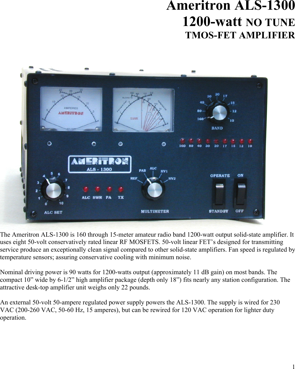
Ameritron 2WUALS13 Ameritron ALS-1300 1200 watt HF linear amplifier User Manual

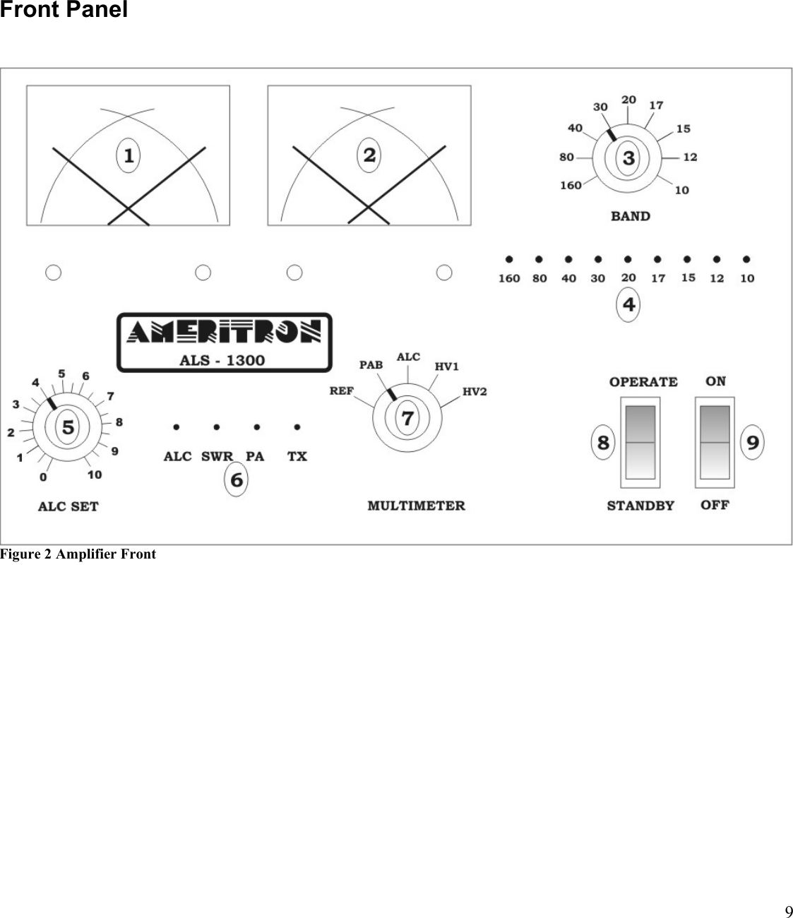
Ameritron Ameritron ALS-1300 1200 watt HF linear amplifier

User manual

1Ameritron ALS-13001200-watt NO TUNETMOS-FET AMPLIFIERThe Ameritron ALS-1300 is 160 through 15-meter amateur radio band 1200-watt output solid-state amplifier. It uses eight 50-volt conservatively rated linear RF MOSFETS. 50-volt linear FET’s designed for transmitting service produce an exceptionally clean signal compared to other solid-state amplifiers. Fan speed is regulated by temperature sensors; assuring conservative cooling with minimum noise. Nominal driving power is 90 watts for 1200-watts output (approximately 11 dB gain) on most bands. The compact 10” wide by 6-1/2” high amplifier package (depth only 18”) fits nearly any station configuration. The attractive desk-top amplifier unit weighs only 22 pounds. An external 50-volt 50-ampere regulated power supply powers the ALS-1300. The supply is wired for 230 VAC (200-260 VAC, 50-60 Hz, 15 amperes), but can be rewired for 120 VAC operation for lighter duty operation.
2Table of ContentsTABLE OF CONTENTS .......................................................................................................................2AMPLIFIER FEATURES ......................................................................................................................3POWER SUPPLY .................................................................................................................................4Power Line Requirements ..................................................................................................................................................................... 4Power Supply Features.......................................................................................................................................................................... 4Power Supply Location .........................................................................................................................................................................4GENERAL INFORMATION ..................................................................................................................5Amplifier............................................................................................................................................................................................... 5Power Supply ........................................................................................................................................................................................5INSTALLATION....................................................................................................................................5Airflow.................................................................................................................................................................................................. 6INTERCONNECTION WIRING.............................................................................................................7AMPLIFIER REAR PANEL ..................................................................................................................8FRONT PANEL ....................................................................................................................................9OPERATION.......................................................................................................................................10MARS OR CAP OPERATION ............................................................................................................10INITIAL OPERATION .........................................................................................................................11CIRCUIT BOARDS.............................................................................................................................12CB-1....................................................................................................................................................................................................12
3Amplifier FeaturesThis amplifier provides the following standard features:Eight conservatively rated, very linear, 50-volt MOSFET transistors Operational in a few seconds, no long filament warm-up timeClean layout with easy-to-service modular constructionFront panel indicators including wrong band and other fault errorsQuiet variable-speed forced air cooling systemPower module balance meteringPower module current and voltage metering with LED illuminationPEP forward output power and PEP reflected output power meteringReflected power protectionBandswitch error protectionStandard negative going ALC output with front panel adjustment controlALC metering and an ALC LED indicatorFully regulated external power supplyCompact size 17.5” deep x 7” high x 10.5” wideWeight amplifier section 23 pounds
4Power SupplyThe power supply for the ALS-1300 is a voltage regulated current limited supply. It contains 14-volt positive and negative supplies as well as dual 50-volt 25-ampere continuous (30-ampere peak) fully current limited supplies. Each PA (power amplifier) module in the ALS-1300 operates from the separate 50-volt sources, giving a total dc input power rating of 2500 watts to the power amplifier modules.Power supply to amplifier interconnections are through a heavy-duty cable using a large Cinch Jones connector. Power Line RequirementsThis amplifier ships wired for 200-260 Vac. The maximum average power line current is 12 amperes at 240 volts. Two 250-volt 15-ampere fuses fuse the power line.Note: 120-volt power mains operation is  possible with  a  reduction in  CW  or RTTY power. Because average power  is  very  low,  SSB  operation  is  unaffected  by  120  volt  operation.  Fuse  size  would  be  25  amperes maximum.Power Supply FeaturesEfficient operation from 200-260 volts ac (12 amperes minimum) and 100-135 volts (20 amperes minimum) Wide range of power line frequencies, 40-400 HzFully regulated current-limited outputsStep-start to limit stress on power supply componentsExceptional filtering and RFI suppressionCompact light-weight design Power Supply LocationLocate the power supply in a convenient ventilated area near the amplifier location. Do not place the power supply next to sensitive equipment like audio processors, transceivers, or microphones. For safety ground the wing nut stud on the supply rear to the station ground buss. The station ground buss should comply with national electrical codes. These codes dictate that station grounds must be bonded to the power mains entrance ground. A station ground that is not bonded to the mains ground does not offer lightning protection!
5General InformationAmplifierThe Ameritron ALS-1300 is a solid-state 1200-watt nominal RF output power 1.8-22 MHz amplifier. This power is peak envelope power, which is the same as actual carrier power on CW. It uses eight exceptionally very low distortion push-pull parallel MRF-150 or equivalent RF power TMOS transistors. The ALS-1300 meets or exceeds all FCC rules governing amateur radio external power amplifiers.Two temperature sensors on each PA (power amplifier) module, with bias tracking FET temperature and fan speed tracking heatsink temperature, control bias and fan speed.Harmonic suppression comes from push-pull operation of linear devices, and a series of high quality 5-pole low-pass filters. This amplifier exceeds all FCC mandated harmonic restrictions. Antenna switching is through a sequenced pair of miniature relays on a plug in board. Relay switching time is approximately five milliseconds. This amplifier’s “relay” jack sources 12 volts when open circuit, and the relay jack current upon closure is less than 20 mA.  This amplifier includes two dual-movement cross-needle meters. This is the equivalent of having four panel meters.  The left hand meter is a dual power amplifier current meter. The right hand meter continuously displays forward RF peak envelope power on one dedicated scale, while the second movement in the right hand meter switches between reflected power, combiner mismatch voltage, ALC, and each power amplifier’s voltages.While this amplifier will run more than 1200 watts PEP output, linearity will suffer. Ameritron recommendsrunning 1200 watts peak power for maximum linearity, at which point this amplifier will have comparable IM performance to the best vacuum tube linear amplifiers. The characteristics of linear high-voltage FET’s are very much like those of triode vacuum tubes.Power SupplyThe ALS-1300 has an external power supply. This power supply normally operates from 200-260 volts at 50-400 Hz. It connects to the amplifier through a single cable. The power supply should be located in a cool spot away from sensitive audio systems or cables. InstallationPlease look your amplifier and power supply over carefully. Observe the air inlet and outlet ventilation holes. Locate the air inlet and outlet areas of the amplifier. Facing the amplifier front panel, the cooling air inlet is on the right side. The warm air outlet is on the left side of the amplifier as viewed from the normal operating position (front view). While the outlet air won’t be particularly warm, it is never a good idea to have it blow into heat sensitive equipment such as transceivers or other power amplifiers. Have the same consideration for your new amplifier and power supply. Be sure the air inlet temperature isn’t substantially above normal room temperature. Ideally the air inlet should be kept below 32° C or 90° F, although temperatures up to 41° C or 106° F are permissible. If ambient temperatures exceed these limits it might become necessary to reduce duty cycle or power.Warning: Do not block cooling air inlets and outlets!Never expose the amplifier to water or mist.
6AirflowThe amplifier must have a clear area to the sides and top for proper airflow, and to the rear for interconnection wiring. It is especially important to avoid obstructions that block the air inlet on the top left and both lower sides. Two inches clearance is normally adequate for full ventilation. Keep any papers or loose objects that might impede airflow away from the air inlets and outlets.Locate the amplifier and power supply away from sensitive equipment such as microphones, audio processing equipment, or low level audio or radio frequency amplifiers. Generally the best location for the power supply is below the operating desk and away from antenna feedlines. This will keep fan noise and any RF coupling to a minimum.The power supply is factory wired for 200-260 Vac. It uses a standard NEMA-6-15P 15-ampere 240-volt plug. The round center pin is the safety ground. Do not remove the safety ground. CAUTION! Before connecting the power supply to an electrical outlet, always be sure you have completed the following four steps:1. Insert the 15-ampere 250V fuses into the two black fuse caps. 2. Insert the fuse and cap assemblies into the power supply’s fuse holders. The fuses lock in place with a slight turn.3. Connect the power supply to the amplifier.4. Be sure the amplifier power switch is turned off.Caution! Fuses have both voltage and current ratings. Use only 250V rated fuses in this device. The voltage rating generally is marked on fuses. DO NOT use automotive-type low voltage fuses in any power line application. For 240-volt operation 15-ampere fast blow fuses are required. Warning: Never insert the power supply cord into the outlet unless the above four steps have been completed!!Position the amplifier at the desired location on your operating desk, position it so you have access to the rear panel, and connect the rear panel cables. Do not connect the power mains at this time!
7Interconnection WiringANTRLYALCOUT INRLYALCTRANSMITTER / TRANSCEIVERALS - 1300POWER SUPPLYINTERCONNECTIONSANTENNA,ANTENNA TUNERS, SWITCHES,FILTERSREMOTEABFUSEFUSEFigure 1 Interconnections
8Amplifier Rear Panel PWR SUPPLY To prevent connecting the power plug wrong, the large black multi-pin connector is indexed by the offset in two round pins. One round index hole is closer to the outer connector edge. Mate the round pins and holes and seat the male plug fully onto the amplifier rear panel pins.ALC Optional connection. Connects to radio ALC input. Mandatory if using a radio over 100 watts.RLY Connect to radio amplifier keying line. Radio must pull this line below 2 volts to transmit.GND Connect to station ground buss. This connection is for safety.IN Connect through good 50-ohm coaxial cable to radio’s antenna output connector. This can be a smaller cable like RG-58/U.OUT To 50-ohm antenna, antenna tuner, power meter. This is the high power output. 50-ohm coaxial cable must safely handle 1200-watts.1.) Connect the station electrical safety ground to the rear panel wing nuts. National safety codes require the station ground be bonded to the power mains safety ground at the building entrance.2.) Connect the power supply to the amplifier.3.) Connect the RLY line to the transceiver’s accessory RELAY or XMT port. This port must pull low for transmit, and be open circuit when receiving. Relay control voltage from the ALS-1300 is 12 volts positive with only 15 mA current. You should always check your transceiver’s manual, but almost any standard transceiver directly interfaces to this amplifier.4.) Connect the OUT (output) port to the appropriate point in your station. This is the high power RF output cable. This connection would go to your 1500-watt rated Power/SWR meter, antenna, or antenna matching device. Good quality Mini-8 or RG-8X cables are acceptable for anything but RTTY use, although larger RG-8 style cables are normally preferred. Your antenna matching system must connect to this port.5.) Connect the IN connector to your transceiver. Do not install any active antenna matching devices on this port. In general the shortest and most direct cable connection is best, although high quality cables can be very long without adverse effect on performance. RG-58/U or Mini-8 (RG-8X) style cables are acceptable. You should never use a tuner of any type on the amplifier input, nor should you drive this amplifier with over 100 watts peak envelope power. Never use a non-FCC accepted device with this amplifier.6.) The ALC line is optional. In general the internal ALC in the transceiver is all that is needed. The ALC monitors the RF output power and reflected power supplied by the ALS-1300 to the load. 7.) Operate the bandswitch manually during initial testing. Do not connect band decoders or computer interfaces until initial tests are completed.
9Front PanelFigure 2 Amplifier Front
10OperationThis amplifier is very simple to operate. Once you have established proper connections please set the amplifier (Fig. 2, ref 3) to one of the following bands:Band Frequency Range Notes160 1.8 - 2.1 MHz80 3.2 - 4.2 MHz40 6.0 - 7.5 MHz30 7.5 - 14.0 MHz Operation locked out in domestic model. Export Only.20 13.5 – 14.5 MHz17 14.5 – 19.0 MHz15 19.0 – 22.0 MHz12 22.0 – 25.0 MHz Operation locked out in domestic model. Export Only.10 28.0 – 30.0 MHz Operation locked out in domestic model. Export Only.Caution: This amplifier is not suitable for 27 MHz. Damage to expensive components such as power amplifier transistors will occur if attempts are made to use this amplifier in the 25-28 MHz frequency range.  MARS or CAP OperationFor licensed amateur radio operators participating in Military Affiliate Radio Systems, this amplifier is suitable for MARS and CAP operation on all frequencies between 1.8 and 22 MHz with some precautions. The upper frequency limits are in bold type in the table above. Do not operate above the bold-type frequency limits in the table above or PA (power amplifier) damage may occur. It is permissible to operate below those limits if you provide additional external harmonic suppression for authorized services such as MARS and CAP. When operated outside the frequency limits above, harmonic suppression might not meet acceptable limits. You may have to use additional external 2nd harmonic filtering. Ameritron guarantees to exceed FCC part 97.307 harmonic suppression standards only inside the frequency ranges listed above. Contact Ameritron with your specific requirements. Ameritron requires proof of a valid MARS or CAP license as well as your own amateur radio license for technical assistance.
11Initial OperationDouble check all wiring and connections (fig. 1) before turning power on. It always pays to be safe. If you are sure you have connected your amplifier correctly, follow the procedures below. The following steps only need to be done on an initial checkout:1. Place the MULTIMETER switch (fig.2 ref 7) in the HV2 position. Place the ALC SET control (fig2. ref 5) full clockwise (10 on scale).2. With the STANDBY/OPERATE switch (fig.2 ref 8) on STANDBY, turn the power switch (ref 9) ON. 3. There will be a slightly delayed click from the power supply. HV2 (fig.2, ref 2) should immediately rise to nearly full scale, and after a slight delay you should hear another click. The meters and BAND  LEDS (fig.2, ref 4) will light up. 4. The HV meter (fig.2, ref 2) should read between 45 and 55 volts.5. Change the meter switch (fig.2 ref 7) to HV1. The voltage should be the same as in step 4.6. Rotate the BAND switch (fig.2 ref 3) through all positions. For any model purchased in the USA, only the 160, 80, 40, 20, 17, and 15-meter bands will actually operate.7. Change the meter switch (ref 7) to REF. This will read reflected power.8. With no modulation in the FM, AM, RTTY, or CW mode adjust your exciter power to low power, around ten watts. This is to have a steady unmodulated carrier. Verify you have very low power, ideally around 10 watts carrier (not critical), and that VSWR of the antenna system is low. You should see almost no deflection on the reflected power scale (fig.1 ref 2). If you see reflected power deflection,check your RF cables. Note: You cannot use a tuner in your radio or between your radio and this amplifier to match the antenna system. Any antenna matching must be between the amplifier and the antenna, and the antenna tuner must be safely able to handle at least 1200 watts of carrier or peak envelope power.9. Place the amplifier in OPERATE position (fig.2 ref 8). Be sure the BAND on the amplifier matches the band selected on the transceiver. 10. Place the transmitter or transceiver into transmit in FM, AM, RTTY, or CW modes. The green TX LED(fig.2 ref 6) should light. The forward power (fig.2 ref 2) should increase to approximately ten times the initial reading, the reflected power should remain low, and the PA current should increase slightly on both scales of the current meter (fig.2 ref 1). No other lights should illuminate. 11. Briefly increase power to 1200 watts output.12. After you have verified all of this, the amplifier is ready to operate.
12Circuit BoardsThere are 10 basic circuit boards plus two power amplifier modules in the ALS-1300. The text below gives a brief description of each board’s function.2KWFThe 2KWF is a high power low pass filter. It is the very large board with large toroid and a few air wound inductors. This board contains filter SWR fault detection, power amplifier unbalance detection, and multiple high power low pass 5-pole filters. Additionally two smaller boards, the antenna relay board RLY and the PA combiner board CMB, attach directly to the low pass filter board. BS1 The BS1 is located behind the BAND switch. It provides all band selection functions as well as band indicators.CB1 The CB1 is located near the front of the amplifier just behind the meters. The CB1 control board provides mostcontrol functions. This includes bias, fan speed, overload protection, and transmit-receive relay sequencing. It is the hub for nearly all functions, including interfaces.CMBThis board combines the outputs of two 600-watt PA modules. It is a traditional 50-ohm “magic T” combiner with an output-matching transformer.FL10The FL10 is optional and only appears in export models. It enables ten meter and twelve-meter operation.MB-1 The MB-1 is located behind the front panel below the meters. It contains peak-envelope-power detection circuits, multi-meter switching, fault indicators, and ALC circuits. There are four power meter adjustments on this board, two for calibration of forward and reflected power and two for forward and reflected peak hold time. Shunts on a header located on the board’s upper edge adjust panel meter brightness.PA BoardsPA boards are located on top of the heatsinks under the filter board shield panel. There are no user adjustments on these boards.PD8The PD8 is located on the right side of the amplifier just above the panel containing the cooling fans. It contains a power splitter and two 5 dB attenuator pads. The splitter and attenuator pads isolate the two power amplifiers from each other, and terminate the PA inputs in 50 ohms over a wide range of frequencies. This is necessary to stabilize the PA modules. Do not remove or bypass the attenuators.
13RJ45The RJ45 board mounts on the rear panel. It contains two RJ-45 jacks for remote control interface.RLYThe RLY board contains two transmit and receive relays, one for RF output switching and the other for RF input switching. T/R relays activate with a low on terminals K (key) J1-3 and RJ1-7. The CB1 board contains the relay timing controls.SWRThe SWR board is on the rear panel in front of the RF output connector. It is a traditional 50-ohm directional coupler. The null adjustment is accessible through a rear panel hole.SchematicsFilter 2KWFrev 03 Mar 2009GndGnd1015204080160081210FL102KWF-1R1Ant R lyPA Out RlyFL 10 FL 10PA Comb OutPA APA BC99GimmikPA INRADIORLY9C23.1C24.1C25.1C26.1C27.1RLY12RLY10RLY8RLY6RLY4RLY212VDCRLY11RLY9RLY7RLY5RLY3C22.1RLY11J1J4C17180C13270C5680C11500C9360L96.5TRLY12RLY10RLY8RLY6RLY4RLY2C20180L106.5TC18180C19180C15270C14270C16270C12360C11360C10360C7680C6680C8680C41500C21500C31500RLY11RLY7RLY5RLY3RLY1L78TL512TL311TL116TL216TL411TL612TL88TC9810pfJ3T2C28270C29.01D2 1N916T1D11N916C21.001ufJ2R250R410kR31kR11kFigure 3
14Bandswitch BS1/Remote+12V7 July 200812V1015204080160G12V1015204080160G+12V+12V10121517203040 80 160987654321SW 1rearviewBS - 1J3D11N4001D21N4001D31N4001D41N4001D51N4001D61N4001J1J2LED1160LED280LED340LED617LED520LED430LED812LED715LED910R11kFigure 4
15Control Board CB1CB1 rev2.1 090227816Bias ABias ABias BBias BKFSPTR SARFK+-GC LASPTRF+-GXX12SC LGGGXXSS6572311010810912313 1 412675FAN123527141136137110115CL K160REARPANELFI LTERTO MB  J1ST BYMI SCIN OUT++GNDHSHSFAFBFANFANFETFETRL2  A NTRL1  I NPBANDFILTER160GNDBias BRL1 INPRL2 ANTBias ABias SWBAND SWITCHDC12VU1pin4 U1pin11SDC12V4042U3DC12VDC12VDC12VDC12VDC12VDC12VDC12VJ8BJ8AC28.1C29.1Q22955Q52955Q13906C8.1RJ1Q93906Q83906Q103904+C30.47+C31.47Q113904J1J5F21AF11AD3D4D2 D7D5 D6C3.1C2.1/50v C14.01/50vU1DU1BU1AJ2J4C11.01C5.01C9.1SSC12.01C6.1J7C35.1C19.1U2BU2DU2AU2C+C21.47Q33904Q43904Q73055Q63055C10.01VR1025k 40%C4.01C1.1/50vC16.1J6C27.1 C26.1 C25.1 C24.1 C23.1C36.1+C3247/50vVR11k 40%VR21k 40%VR41k 40%VR31k 40%VR81k 40%VR71k 40%VR61k 40%+C3347/50vVR51k 40%C37.1C34.1J3D10916C13.1Q123055C7.01/50VC17.1C18.1+C20.47U5LM7809U4ALM358U4BLM358D9D8C22.47C15.47U4pin4U4pin8U2pin11U2pin4DC12VSwitchedDC12VZD15.1vR5910k R5810kR1410R55100 R54100R571kR5010KR494.7kR514.7kR164.7kR910kR11100R2927kR5100R131kR171k R1510kR1210kR254.7kR28100R244.7kR1810R221kR206.8kR6100kR71kR3210kR314.7kR404.7kR4110kR4310kR424.7kR2100R4100R451kR441kR471kR461kR301kR362.2kR351kR3810kR81kR3100R1910R231kR53100 R56100R334.7kR372.2kR3910kR3410k R521kR4810KR10100R274.7KR264.7KR216.8kR11kFigure 5
16Combiner 2000 watt CMBCMB 081217 rev0a10050 OHMS  OUT50 OHMS  IN50 OHMS  INT5T6PA APA BFigure 6Filter FL10FL10 081210OutInL21C4130pFC3130pFC2130pFL11C1130pFFigure 7
17Metering Board MB1MB1 Rev3 090227PIN 1...GND      2...FWD      3...MM -      4...MM +      5...LMP      6...GND+-CTRL  J1METER BRIGHTNESS              J4PIN 1...V2      2...V2      3...V1      4...V1PIN 1...GND    2...12 -    3...12 +    4...FW D PW R    5...RFLCTD PW R    6...TRANS MIT LE D    7...COMBINER LED    8...SW R LED    9...ALC VOLTAGE OUT   10...COMBINER LVL1211109876543211,2 low2,3 highMULTI METER    J2CURRENT      J3+12-12V84PEAK METER / ALCALC75632131256710981213 14SW 18V8V-12V+12V+12V8V-12V-+TC LASC114GLFF w dR e fG n dG n dMULTI METERCURRENTMETER BRIGHTNESSREF CALREF SPEEDCALFWD SPEEDCTRL-+C14.1D3LED1D2LED2Q12N3904C15.1Q22N3904D1LED3D61N916D21N916C16.1D4LED4C12.1C7.1U2B LM358U1ALM324R3910k 10%+C42.2uF+C32.2U1CU2AU1DU1BR16 1m 40%R151m 40%C17.1C13.1RCV1V2RCAV1AV2C5.1J2J3J4R22.5k 40% C 2.1D31N916C8.01D11N916J1C6.1C1.1R12.5k 40%D41N916D51N916C9.01C10.1D71N916C11.1D81N916D91N916R221kR401kR2347kR411kR2447kR2810kR1910R311mR34220KR291kR384.7KR321kR710R1168KR1068KR131k R141kR35.6kR61mR184.7kR204.7kR1210R21100R45.6kR81MR910kR174.7kR510kR33220kR26560R251kR271k R306.8kR35100kR371kR361kFigure 8
18PA Boards081217 Revision 0aPAM-600RedBrnOrg0Red0YelFB1FB2C11330pFP1CONNPA Out  PA In   X1C13.001uFC9.001uFC19.001uFC2.001uFC23.33uFT2T1C3470pFC20470pFT4T3C21.33uFV150VDCC24.33uFC26100uFC25.47uFC22.33uFQ1Q2C7.33uFC6.33uFC1.1uFC4.1uFC5.1uFC8.1uFC17.33uFC16.33uFC12.1uF C14.1uFC15.1uFC18.1uFQ4Q3C10470pFR1NTCR2NTCR21470R12470R28470R5470R18 22R17 22R16 22R13 22R14 22R15 22R618R818R91kR71kR41R318R111R1018R2218R2418R251kR231kR201R1918R271R2618Figure 9Power Divider PD8081126PD8  rev0-8db splitterT1T2In      Out      Out     R7100R527R4200R6200R3200R227R1200Figure 10
19Interface Connections RJ45  -  J1  -RJ45 Rev0 090217  -  J2  -C10.1uFD2D1J3CONNPin1Pin2Pin7 Pin5 Pin3Pin4Pin8 Pin6Pin1Pin2Pin7 Pin5 Pin3Pin4Pin6Pin81/2WR2560R11kFigure 11
20Relay BoardPA OUTHD1 HD4RL4RL1ANTENNARADIOPA INRLA 081210MAY 21, 2008Figure 12Reference figures and drawingsFigure 1 Interconnections ....................................................................................................................................... 7Figure 2 Amplifier Front......................................................................................................................................... 9Figure 3 ................................................................................................................................................................. 13Figure 4 ................................................................................................................................................................. 14Figure 5 ................................................................................................................................................................. 15Figure 6 ................................................................................................................................................................. 16Figure 7 ................................................................................................................................................................. 16Figure 8 ................................................................................................................................................................. 17Figure 9 ................................................................................................................................................................. 18Figure 10 ............................................................................................................................................................... 18Figure 11 ............................................................................................................................................................... 19Figure 12 ............................................................................................................................................................... 20

Navigation menu