Alvarion Technologies EXTR-50 BreezeMAX Extreme 5.8 Base Station User Manual BMAX Extreme System Manual
Alvarion Technologies Ltd. BreezeMAX Extreme 5.8 Base Station BMAX Extreme System Manual
UserManual.wiki
>
Alvarion Technologies
>
EXTR-50 User Manual
>
User manual 2
Contents
1.
user installation manual
2.
Updated user manual Correspondance 39238
3.
Professional Installer qualifications and Quick Installation guide
4.
User manual 1
5.
User manual 2
User manual 2
Navigation menu
Upload a User Manual
Namespaces
Wiki Guide
HTML
PDF
Info
Views
User Manual
Discussion / Help
Navigation
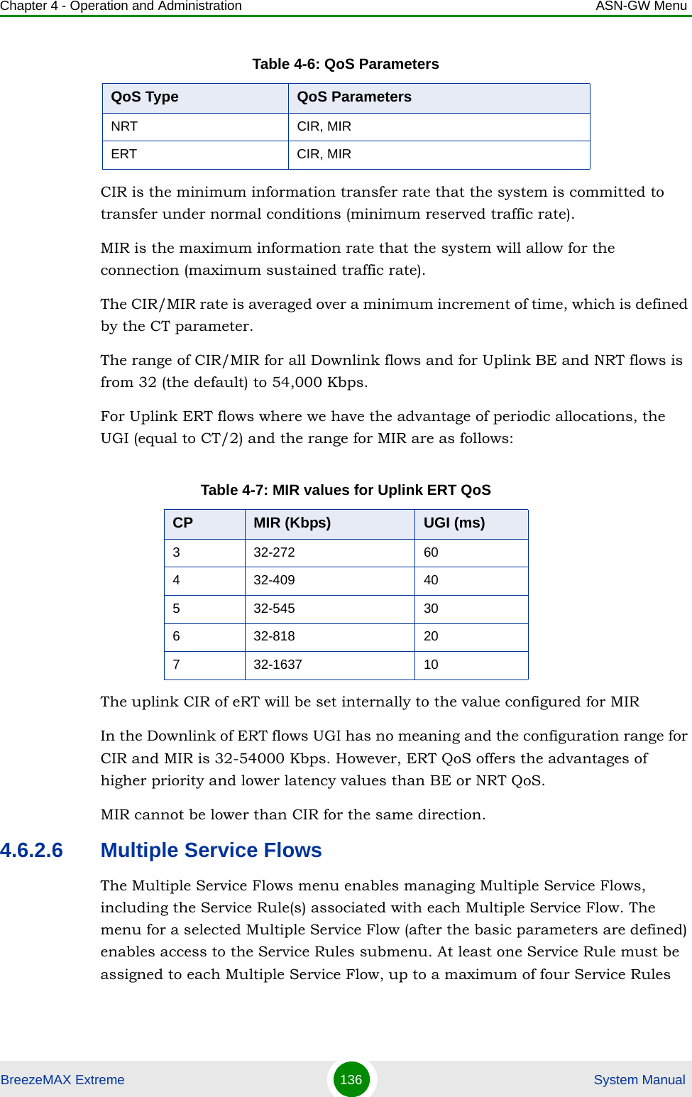
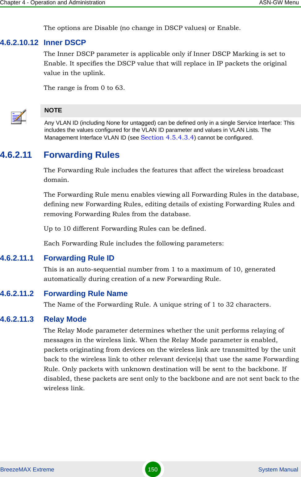
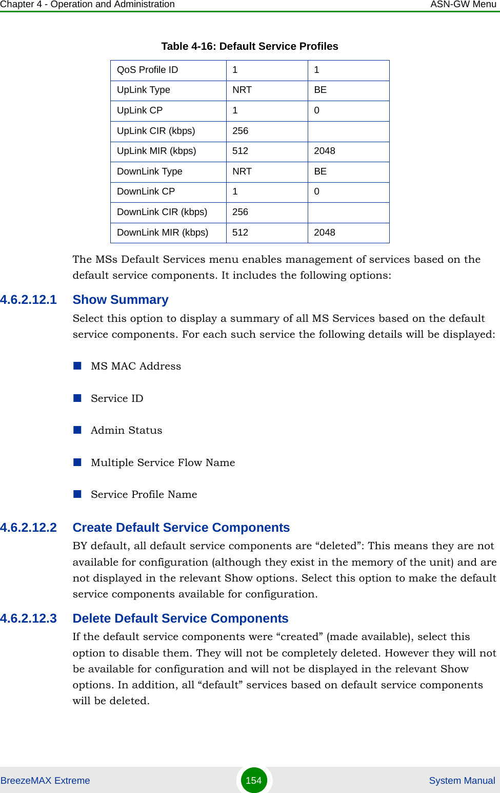
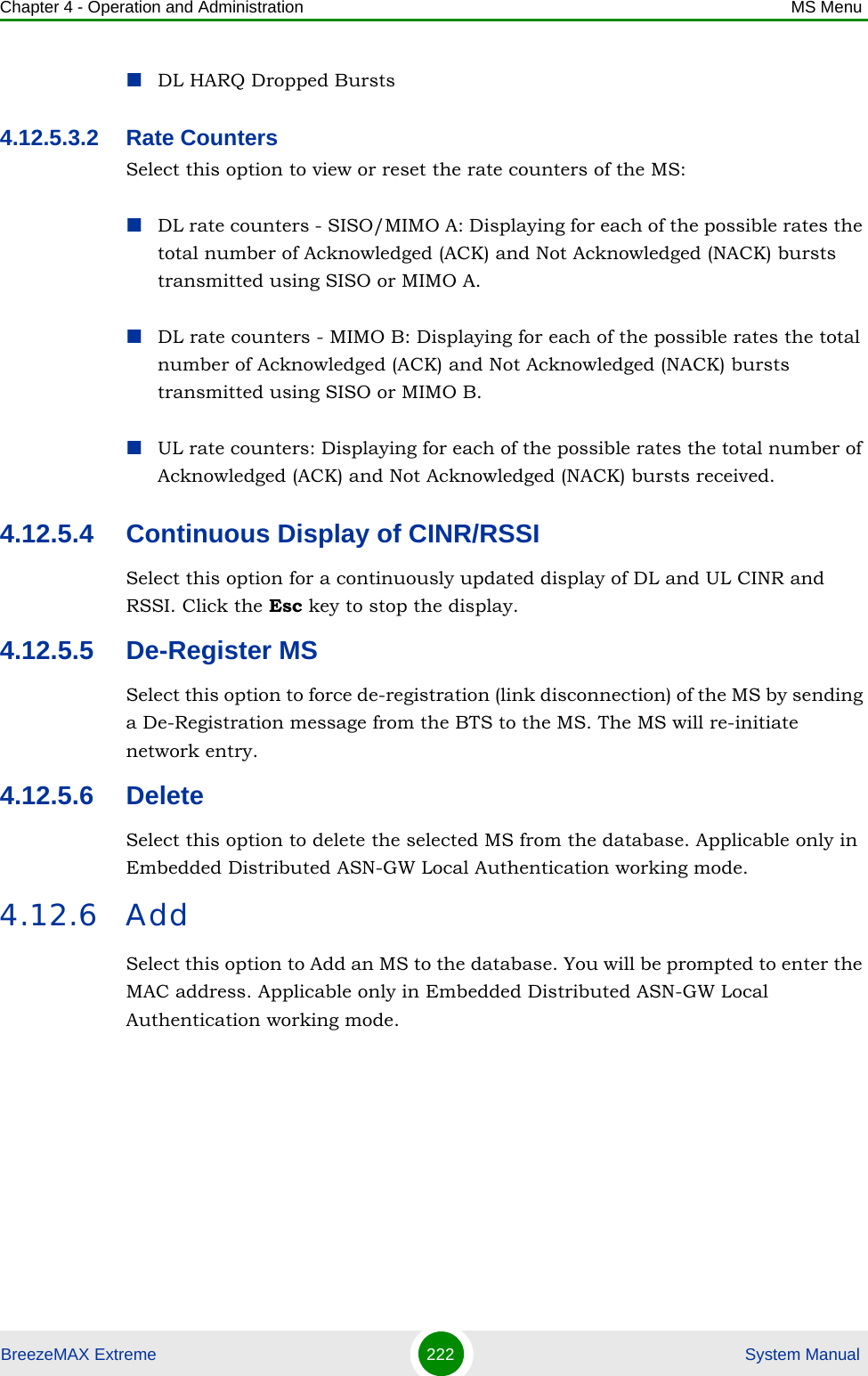
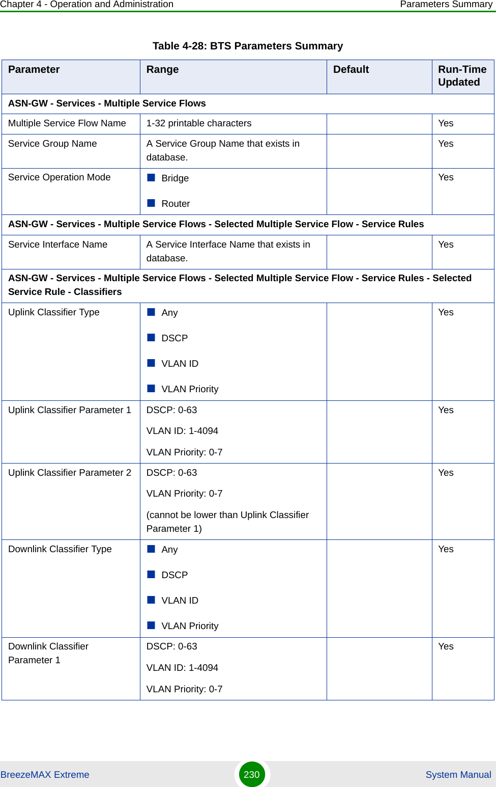
![Chapter 4 - Operation and Administration ASN-GW MenuBreezeMAX Extreme 152 System ManualCIR is the minimum information transfer rate that the system is committed to transfer under normal conditions (minimum reserved traffic rate). MIR is the maximum information rate that the system will allow (maximum sustained traffic rate). The CIR/MIR rate is averaged over a minimum increment of time, which is defined by the CT parameter.The range is from 32 (the default) to 54,000 Kbps.MIR cannot be lower than CIR.4.6.2.12 MSs Default ServicesThe BTS is supplied with a set of default service components supporting typical Management and Ethernet CS Data services. The default service components cannot be deleted. However, they may be updated.The default service components are:NRT CIR, MIRTable 4-12: Default Forwarding RulesForwarding Rule Name [[FrwRuleEth]]Relay Mode EnableUnknown Address Forwarding Mode ForwardQoS Type BECP 0MIR (kbps) 512Table 4-13: Default Service InterfacesService Interface Name [[SrvIfcEth]]Forwarding Rule Name [[FrwRuleEth]]CS Type Ethernet CSInner DSCP Marking DisableVLAN Interfaces EnableVLAN Transparency DisableTable 4-11: QoS ParametersQoS Type QoS Parameters](https://usermanual.wiki/Alvarion-Technologies/EXTR-50.User-manual-2/User-Guide-1472912-Page-43.png)
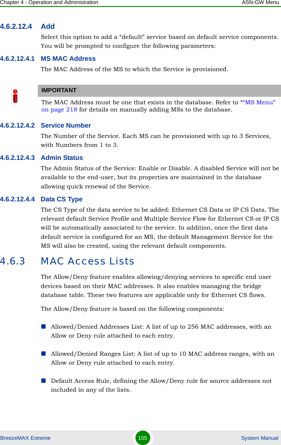
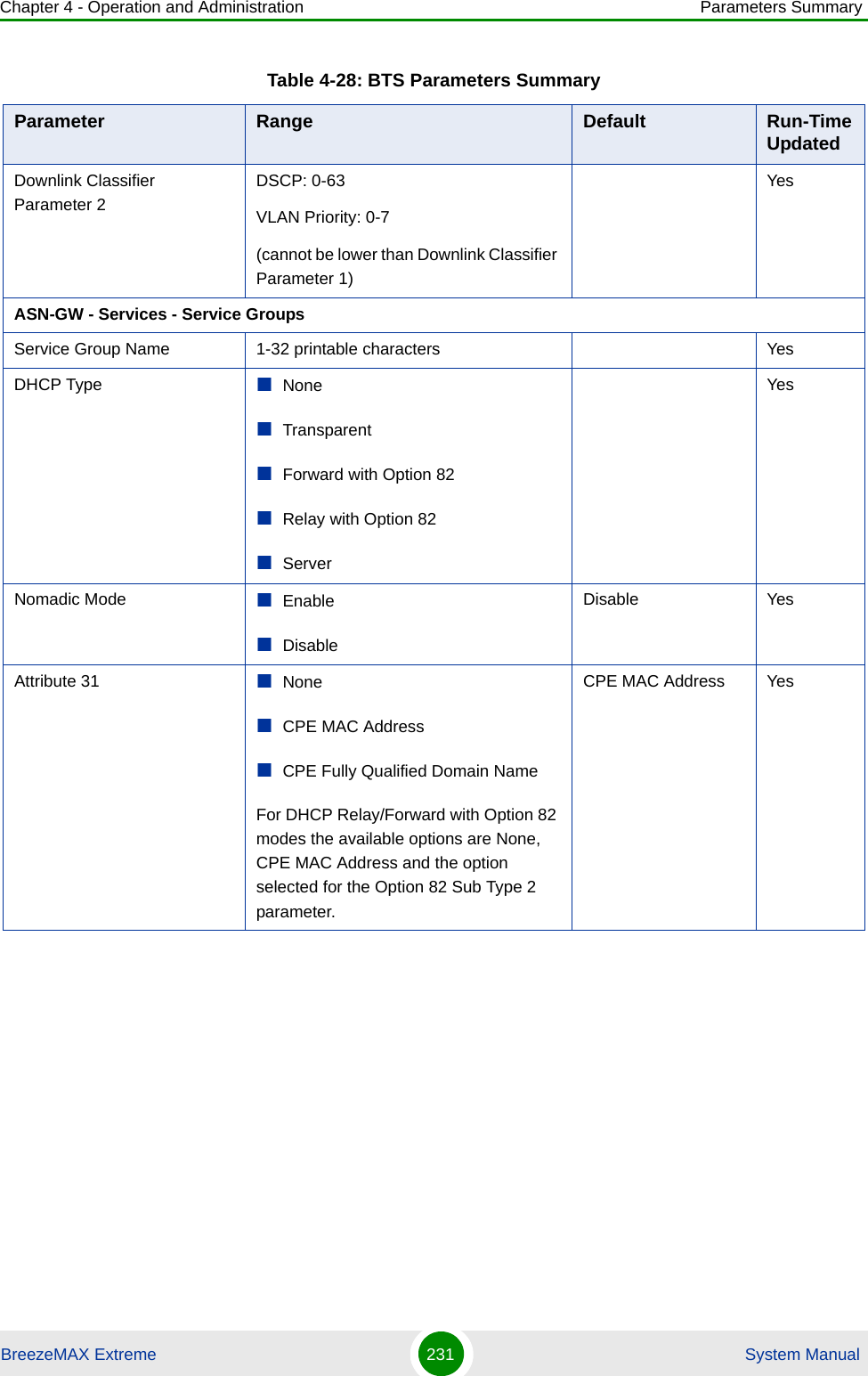
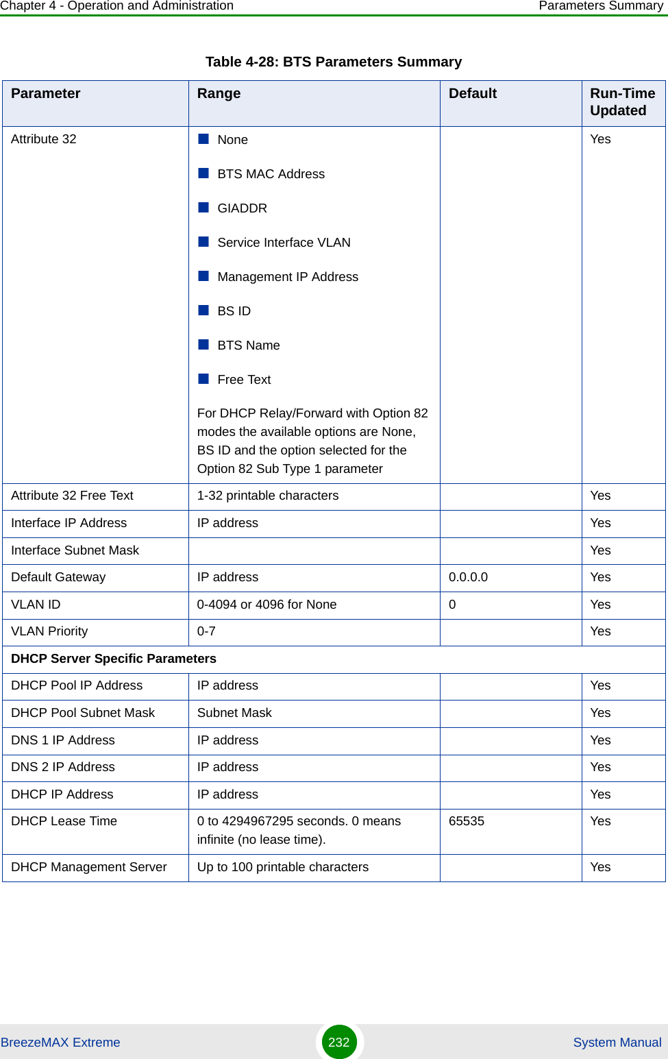
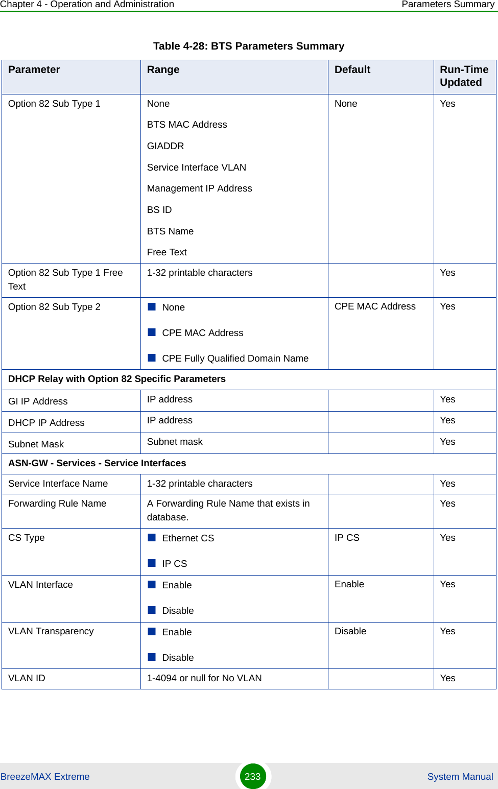
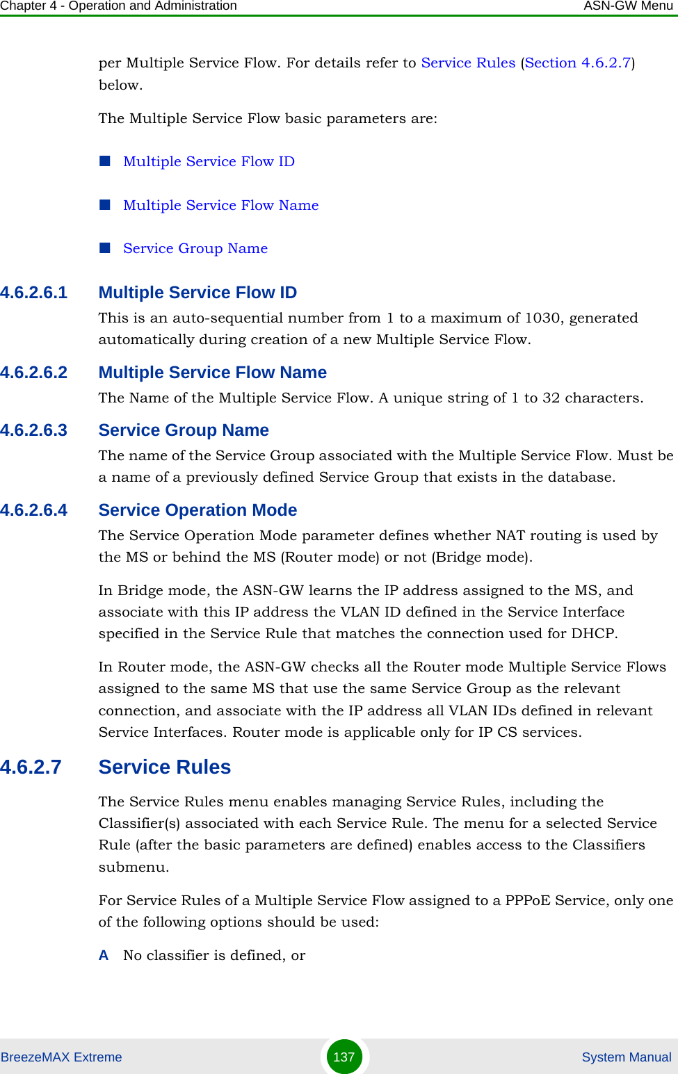
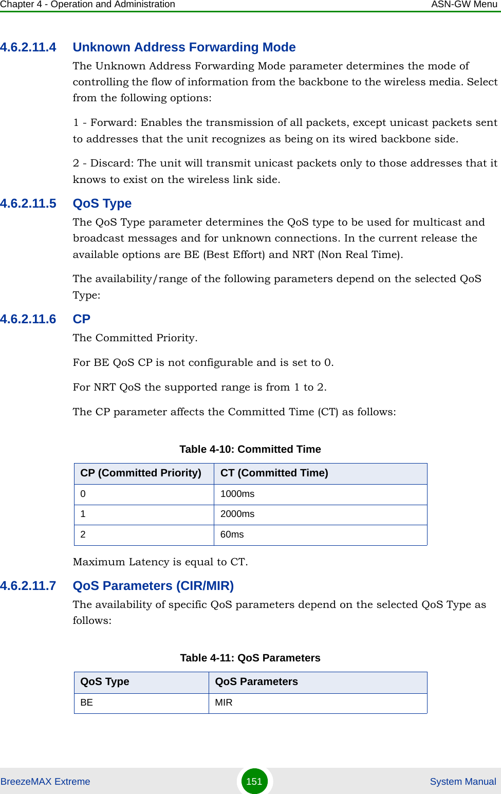
![Chapter 4 - Operation and Administration ASN-GW MenuBreezeMAX Extreme 153 System ManualVLAN ID 1234VLAN Priority Marking EnableVLAN Priority 0Table 4-14: Default Service GroupService Group Name [[srvGroup]]DHCP Type TransparentNomadic Mode DisableAAA Attribute 31 NoneAAA Attribute 32 NoneInterface IP Address Management Interface IPInterface Subnet Mask Management Interface Subnet MaskDefault Gateway Management Interface GatewayVLAN ID Management VLANTable 4-15: Default Multiple Service FlowsMultiple Service Flow Name [[msfMng]] [[msfEth]]Service Group Name [[srvGroup]] [[srvGroup]]Service Operation Mode Bridge RouterService Rule ID 1 1Service Interface Name [[SrvIfcIp]] [[SrvIfcEth]]Classifier ID 1 1Uplink Classifier Type DSCP DSCPUplink Classifier Parameter 1 6 0Uplink Classifier Parameter 2 6 0Downlink Classifier Type DSCP DSCPDownlink Classifier Parameter 1 6 0Downlink Classifier Parameter 2 6 0Table 4-16: Default Service ProfilesService Profile Name [[SrvProfMng]] [[SrvProfEth]]Service Profile Type Management DataTable 4-13: Default Service Interfaces](https://usermanual.wiki/Alvarion-Technologies/EXTR-50.User-manual-2/User-Guide-1472912-Page-44.png)