Altai Technologies WA8011NAC-X Altai A8n (ac) Super WiFi Base Station User Manual A3 Series Configuration Manual
Altai Technologies Limited Altai A8n (ac) Super WiFi Base Station A3 Series Configuration Manual
UserManual.wiki
>
Altai Technologies
>
WA8011NAC X User Manual
Users Manual
Navigation menu
Upload a User Manual
Namespaces
Wiki Guide
HTML
PDF
Info
Views
User Manual
Discussion / Help
Navigation

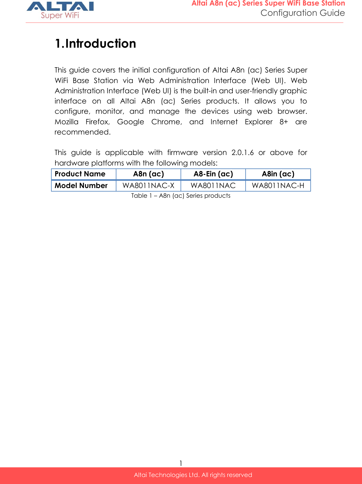
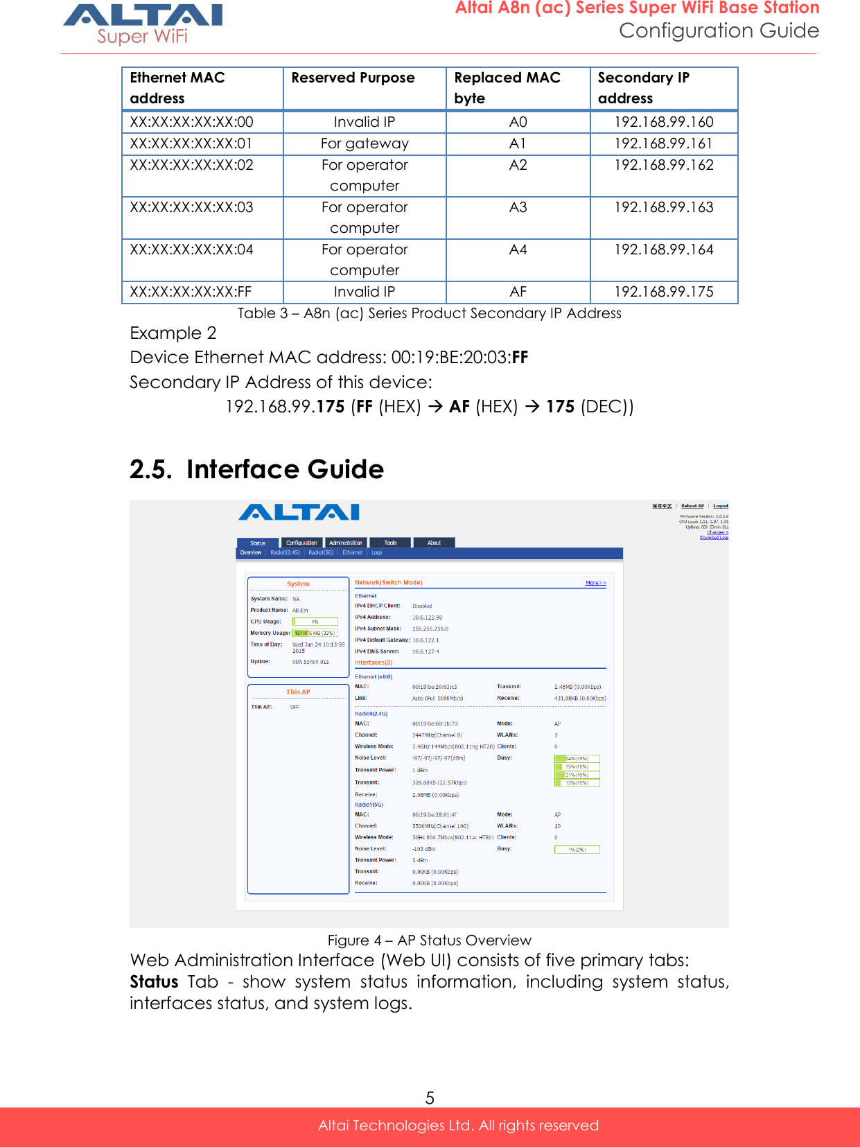
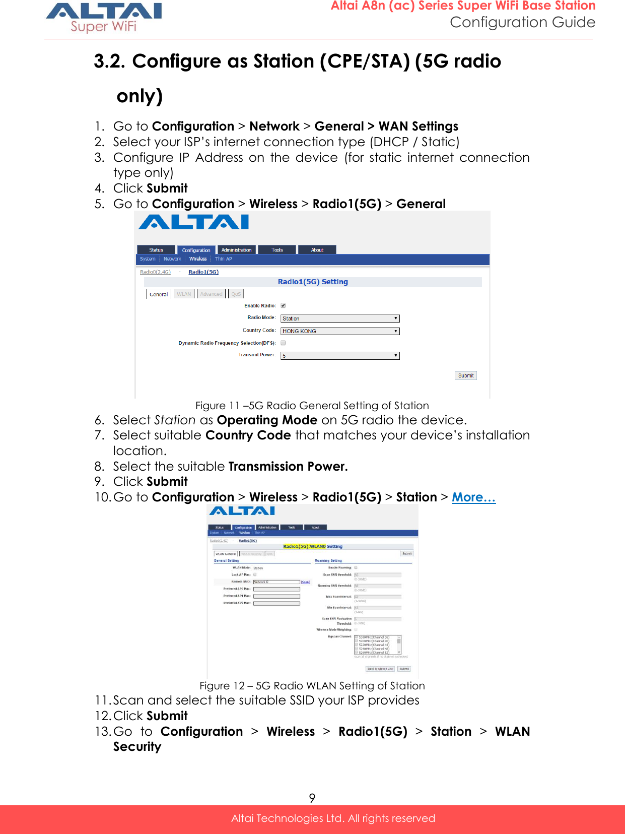
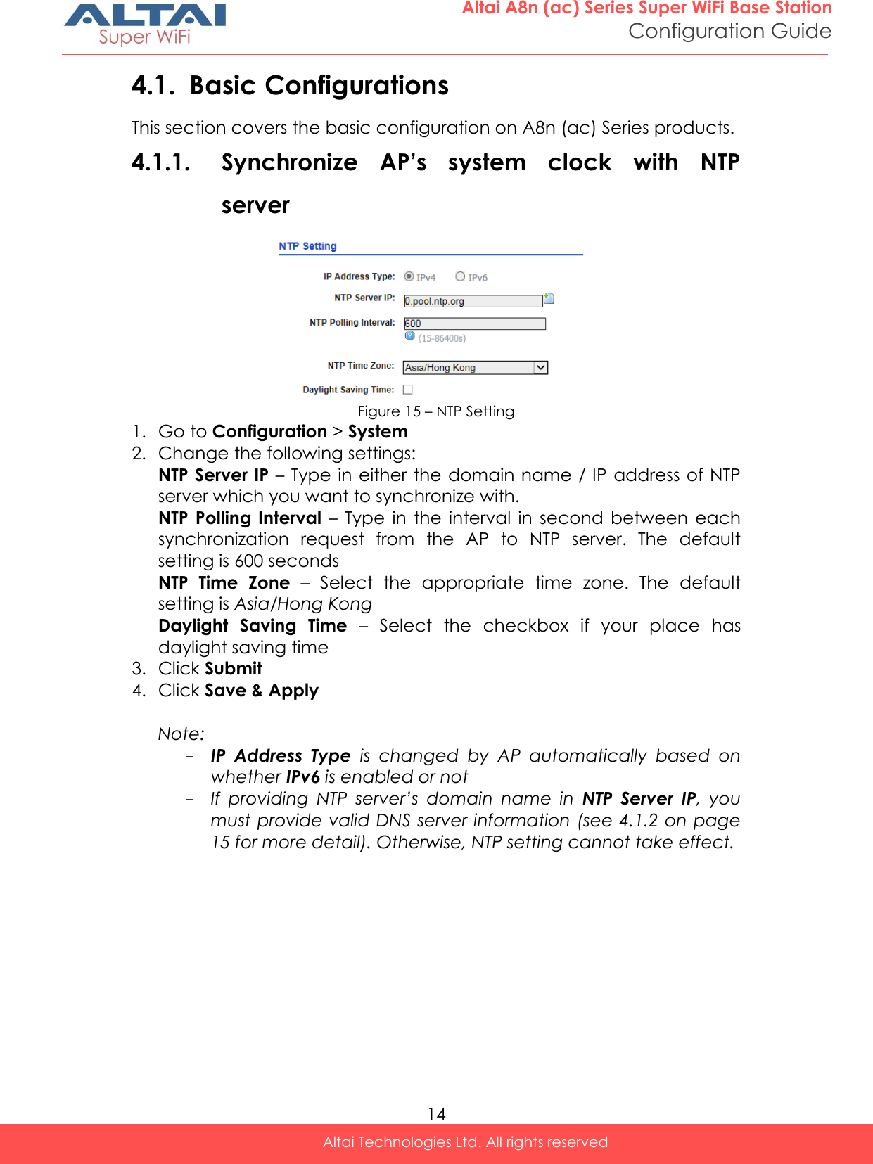
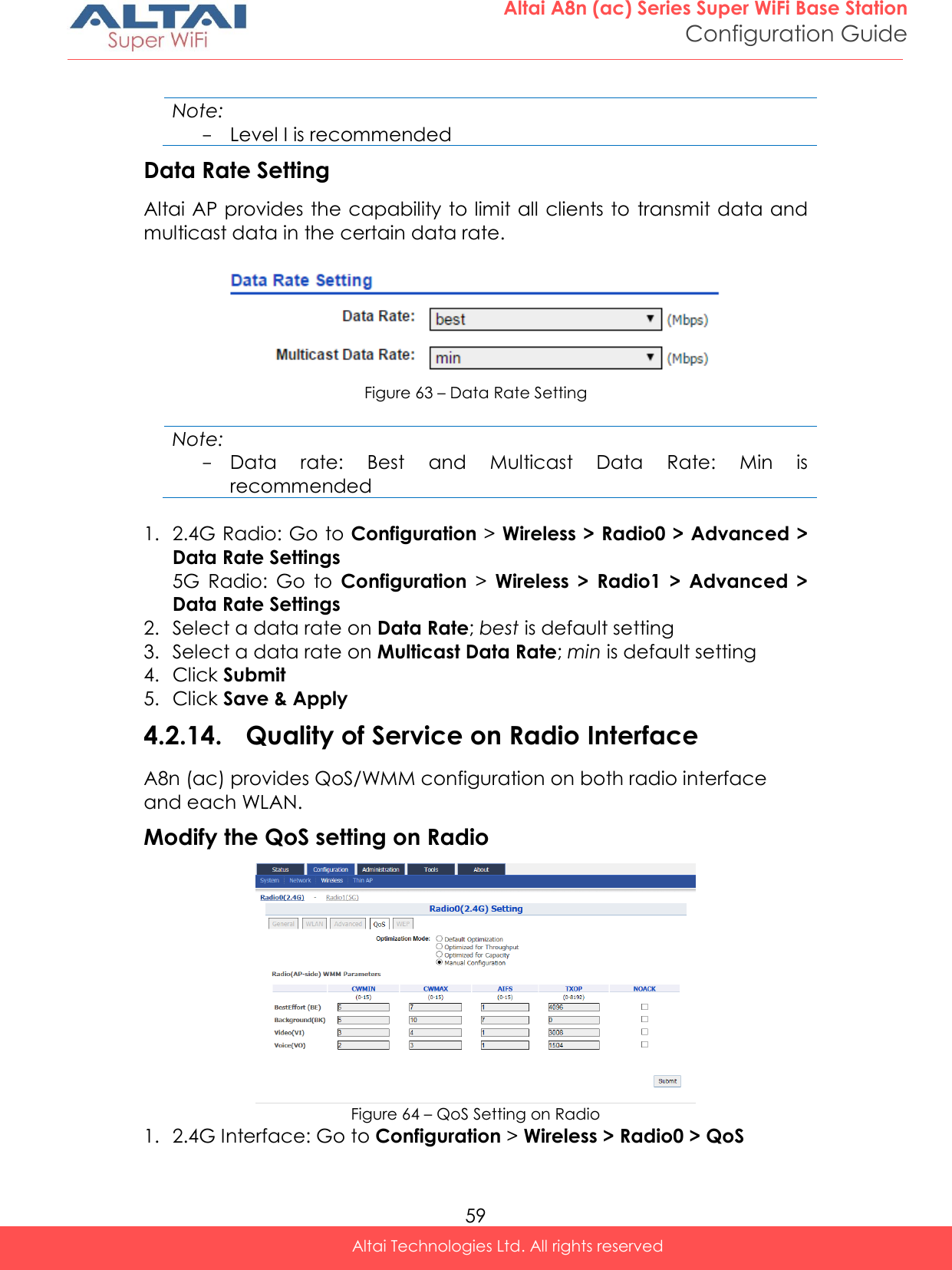
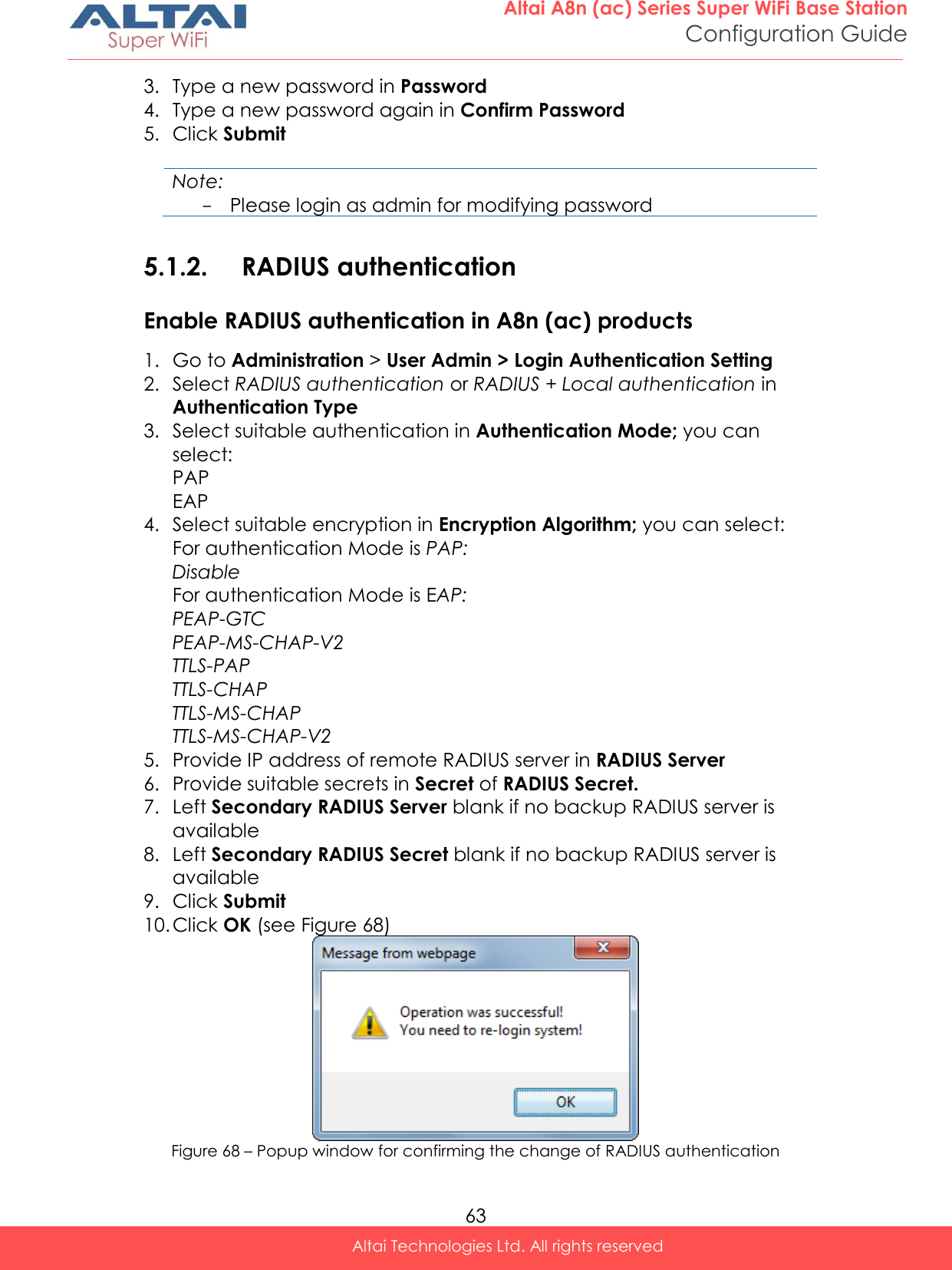
![17 Altai A8n (ac) Series Super WiFi Base Station Configuration Guide Altai Technologies Ltd. All rights reserved Note: - Country code enforces regulatory restrictions on radio frequencies and maximum transmission power that the AP can operate in. Wireless Mode – Select suitable Wi-Fi operating mode for the AP; 2.4G 11Mbps (802.11 b) 2.4G 54Mbps (802.11 bg) 2.4G 54Mbps (802.11 g-only) 2.4G 144Mbps (802.11 ng HT20); Default Setting 2.4G 144Mbps (802.11 n-only HT20) 2.4G 300Mbps (802.11 ng HT40+) 2.4G 300Mbps (802.11 n-only HT40+) 2.4G 300Mbps (802.11 ng HT40-) 2.4G 300Mbps (802.11 n-only HT40-) Legacy 11b Data Rate Support [Optional] – Select a suitable option for the legacy client compatibility. In order to enhance the spectrum efficiency, low data rates (1/2/5.5/11M) should be eliminated. The options include: 1/2/5.5/11M (Best compatibility /Poor performance) All legacy clients will be supported 5.5/11M (Good compatibility /Good performance) Clients only capable of 1/2Mbps will not be supported Disable All (Poor compatibility/ Best performance) Clients only capable of 802.11b standard will not be supported Note: - 2.4G 11Mbps (802.11 b) is not applicable. Radio Frequency – Choose the operating channel for the radio interface; AP selects the channel with the least amount of interference if Auto is selected. An optional feature Periodic Auto channel Selection will be shown if Auto is selected. 2412MHz (Channel 1) is the default setting Note: - Select the radio frequency based on the result of channel scan is recommended Transmission Power – Select the total transmission power for the radio interface. Maximum Client – Specify the maximum associated client between 1 and 512 that the radio interface serves. 512 is the default setting.](https://usermanual.wiki/Altai-Technologies/WA8011NAC-X/User-Guide-2975624-Page-25.png)
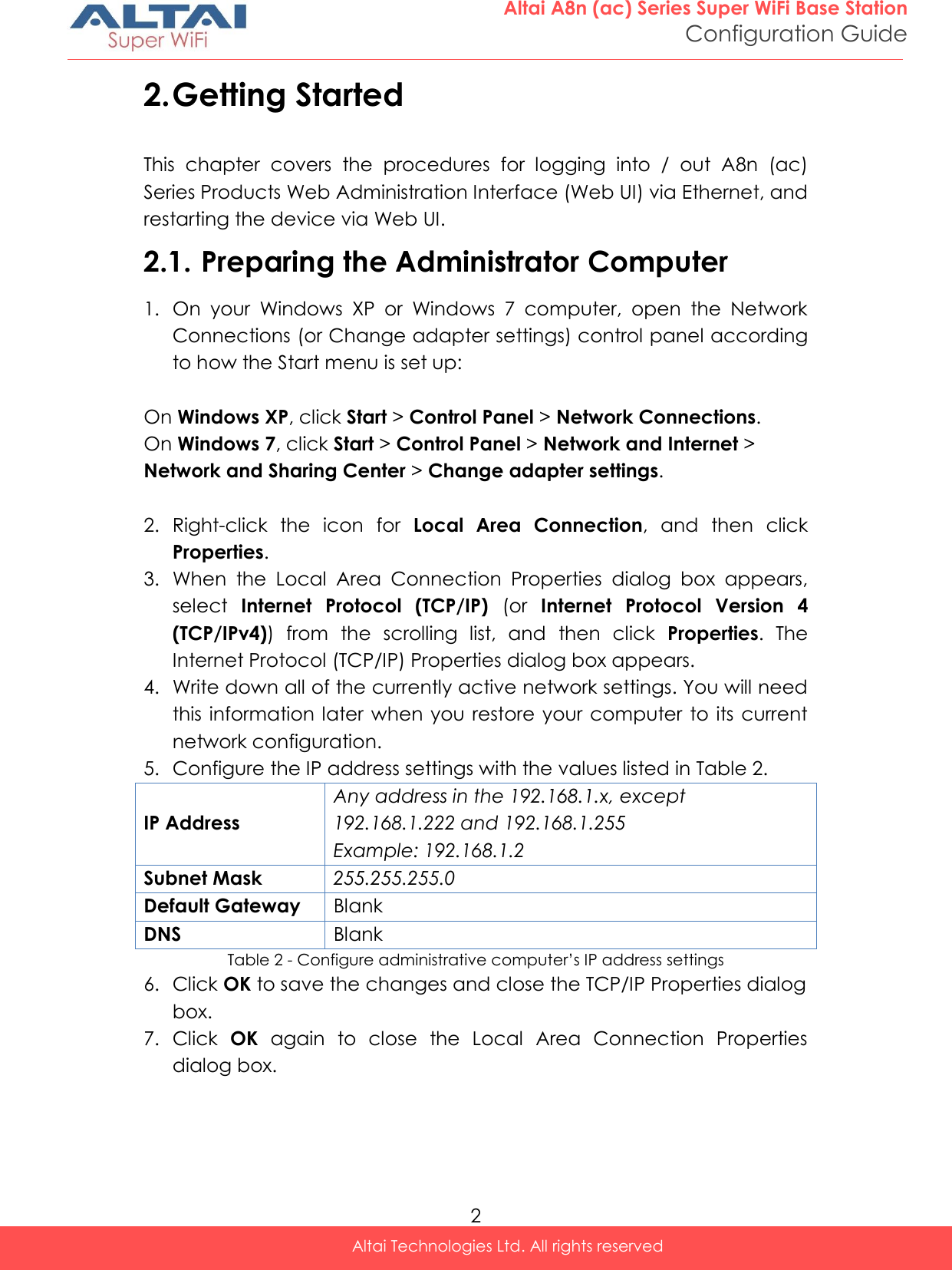
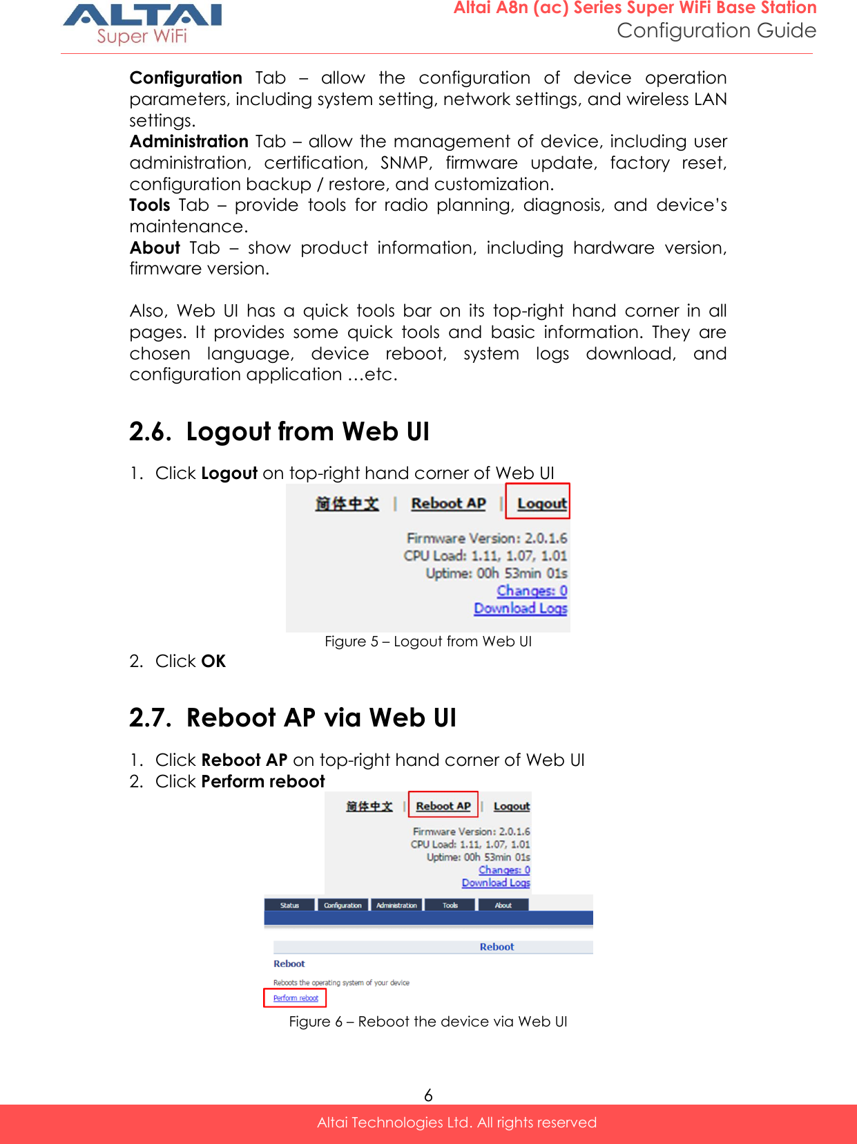
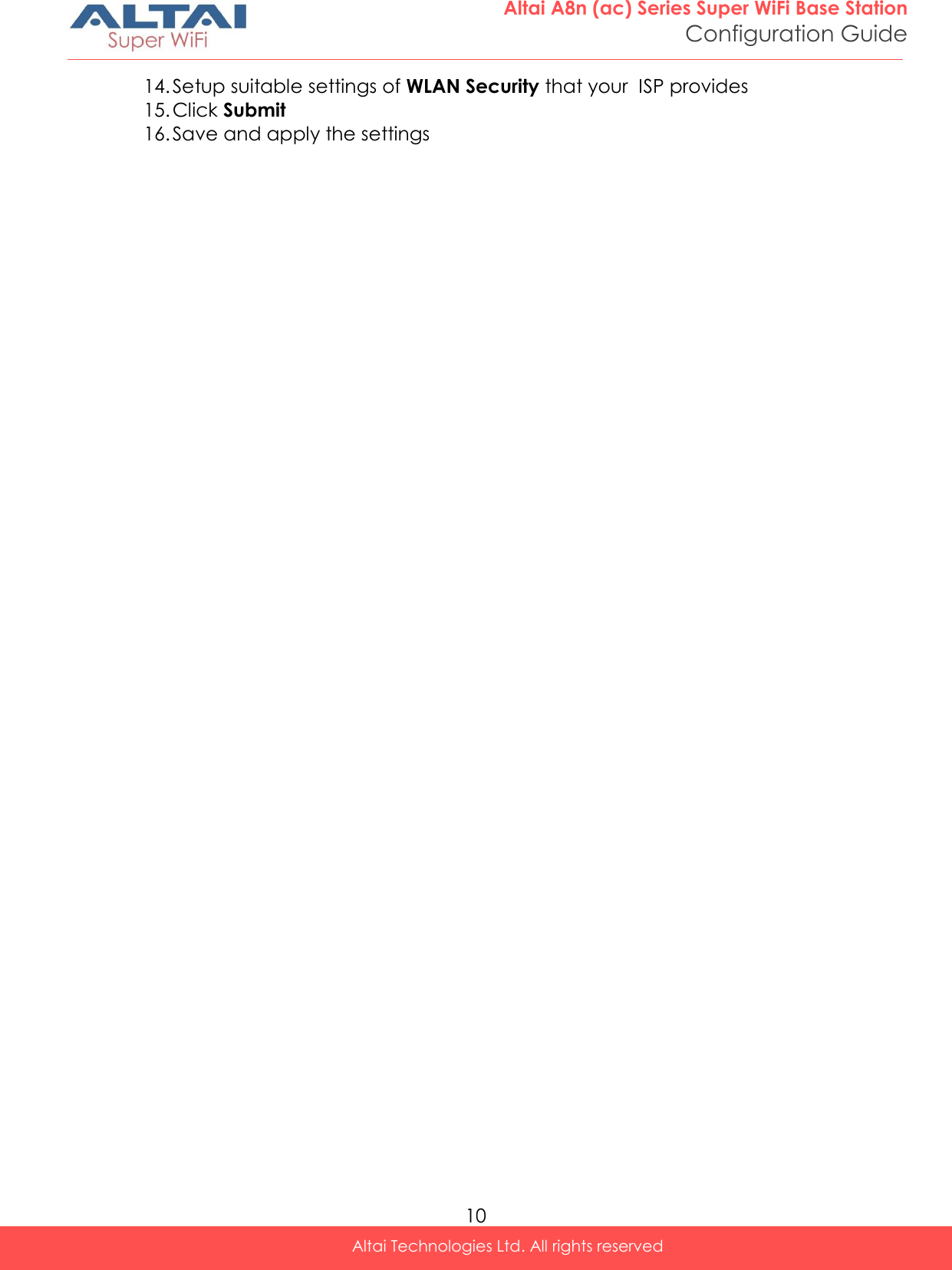
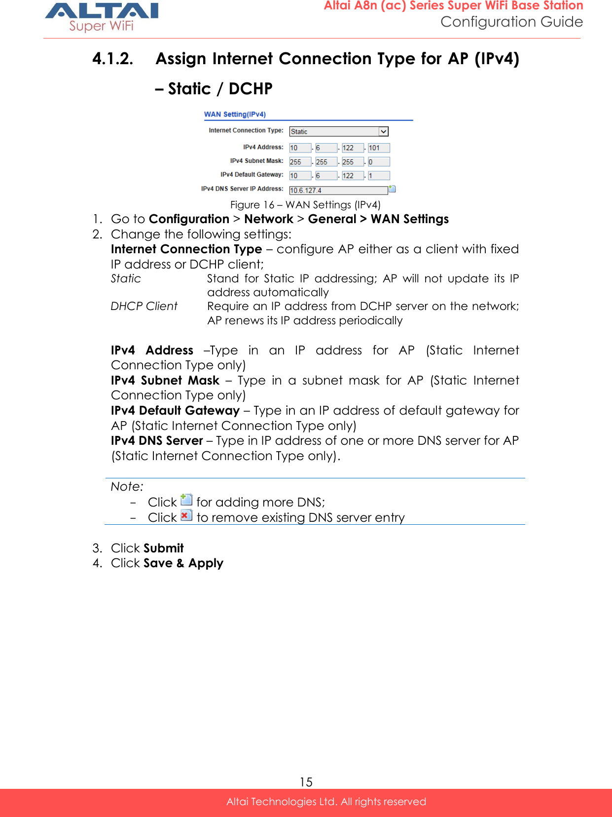
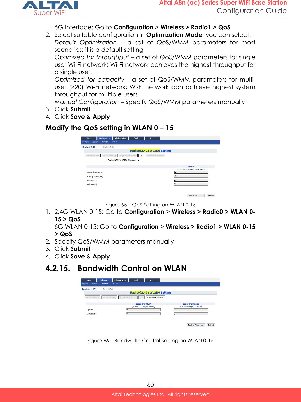
![18 Altai A8n (ac) Series Super WiFi Base Station Configuration Guide Altai Technologies Ltd. All rights reserved Disable HT20/HT40 Auto Switch [Optional] – If select the checkbox, AP will NOT switch the channel width between 20 MHz and 40 MHz automatically. This option is only available if any wireless mode with HT40+/- is selected. User Isolation in different WLAN (SSID) [Optional] - Select the checkbox to block the users’ communication across different SSID in the AP directly. Periodic Auto Channel Section [Optional] – Select the checkbox to enable a scheduled channel selection task on the radio interface. Schedule Mode Select exact time and day(s) for selecting radio frequency for the interface Periodic Mode Select a countdown timer (minute) for selecting radio frequency for the interface; 0 denotes disable. Range Optimization [Optional] – Select a coverage range for optimization. ‘Auto’ is the default value. Sector Power Control [Optional] – Select the checkbox to enable a feature to assign a transmitting power for each sector. 5. Click Submit 6. Click Save & Apply](https://usermanual.wiki/Altai-Technologies/WA8011NAC-X/User-Guide-2975624-Page-26.png)
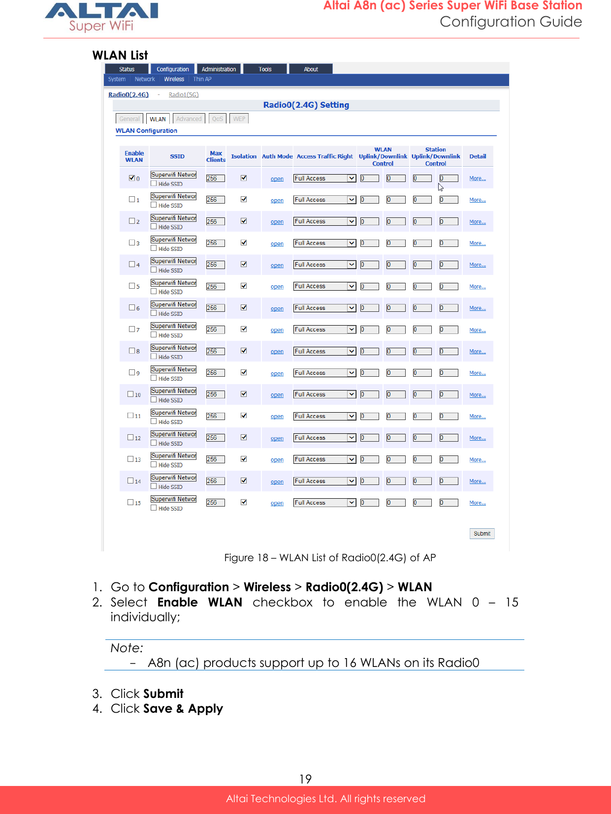
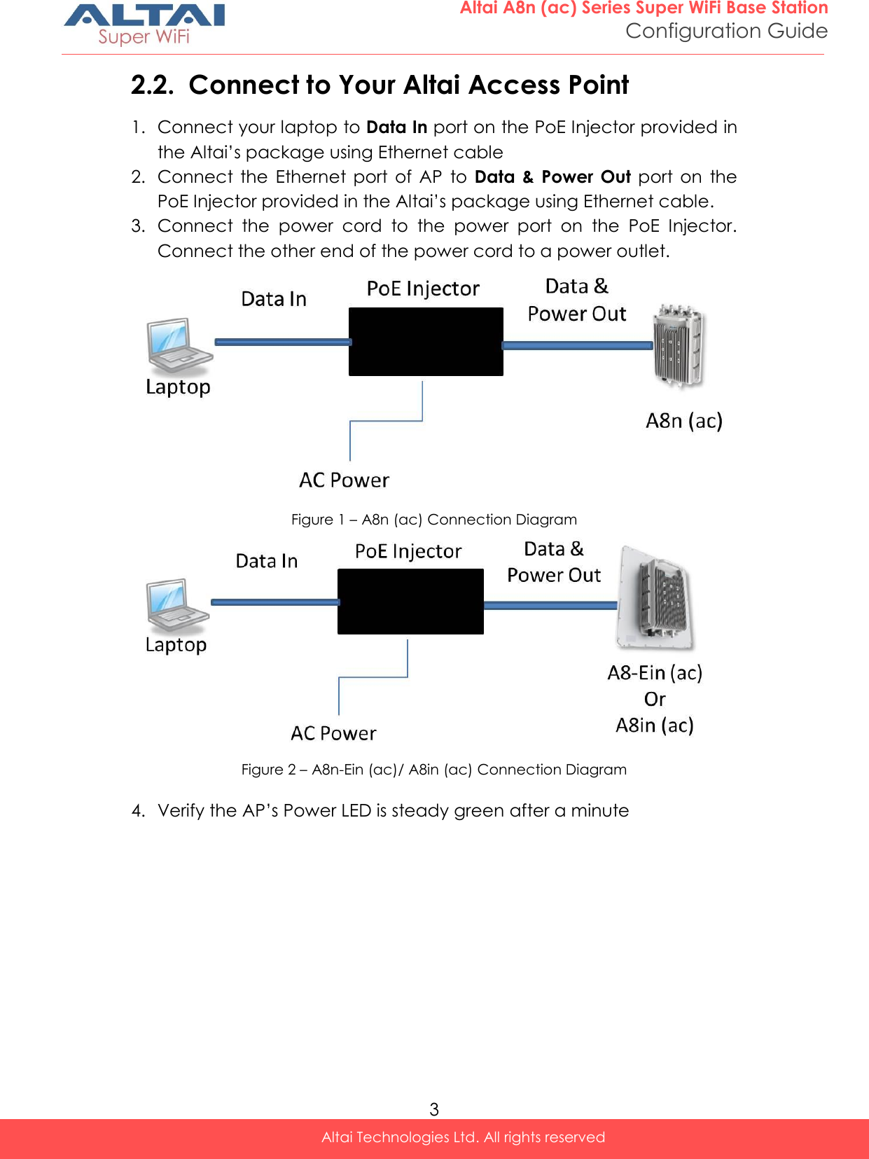
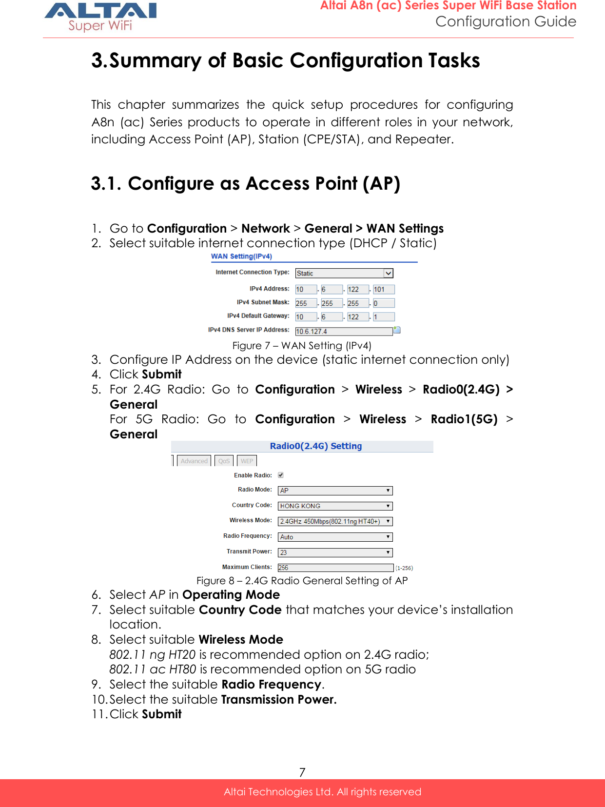
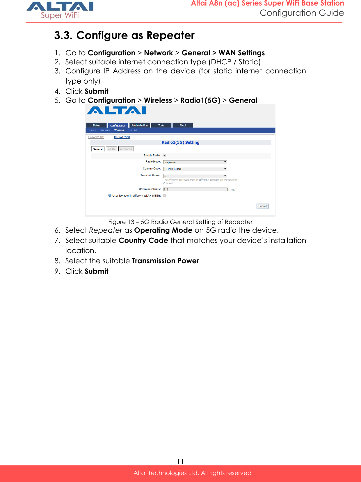
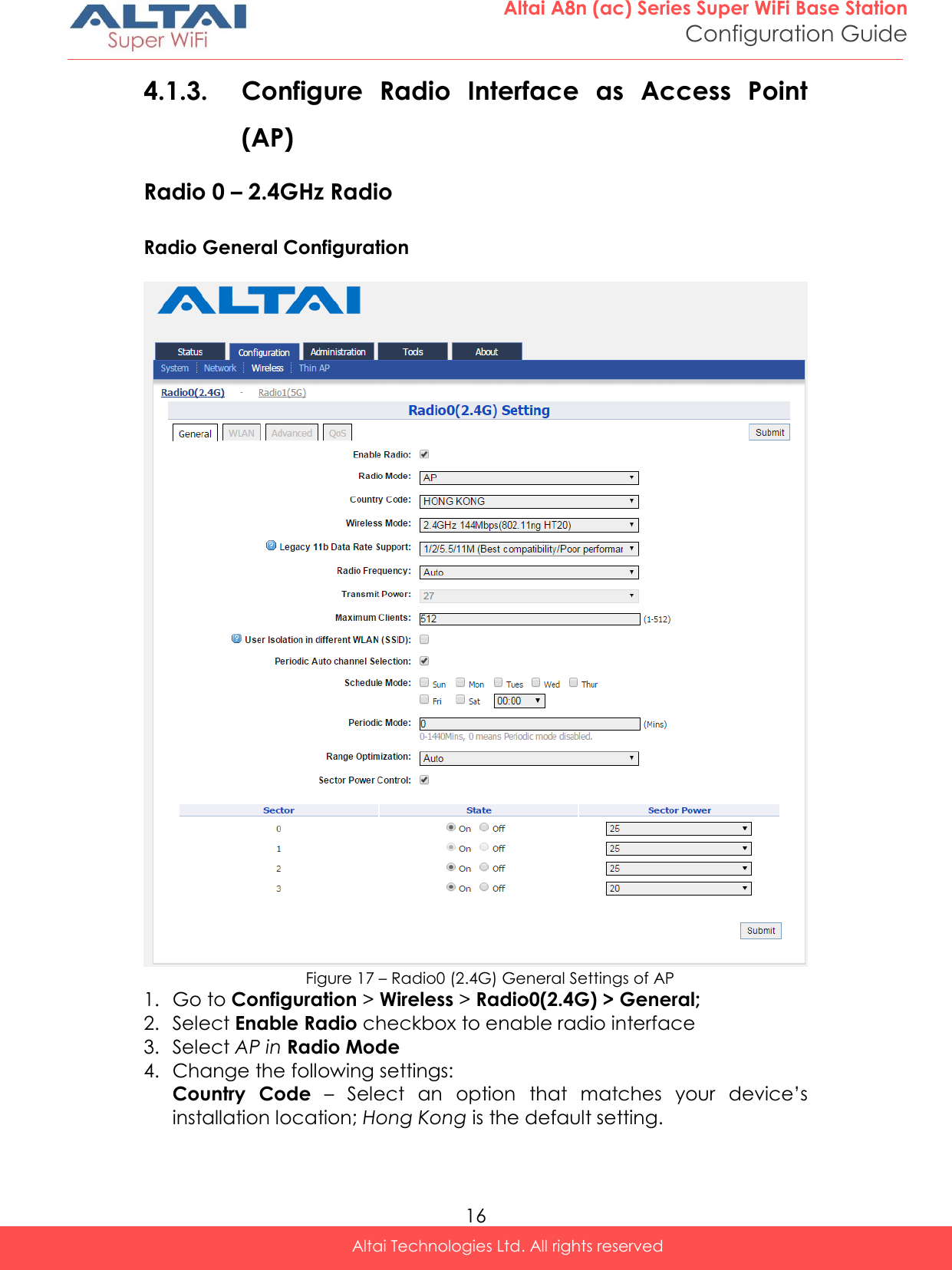
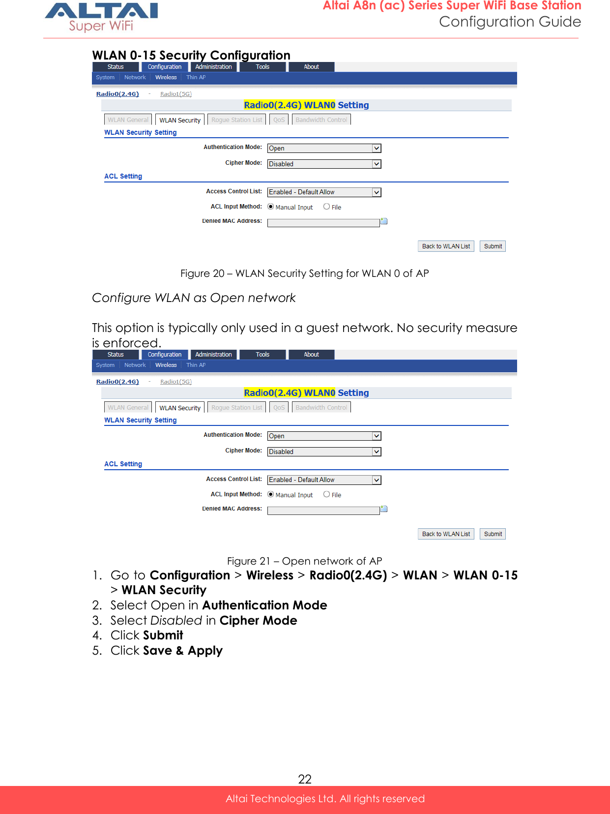
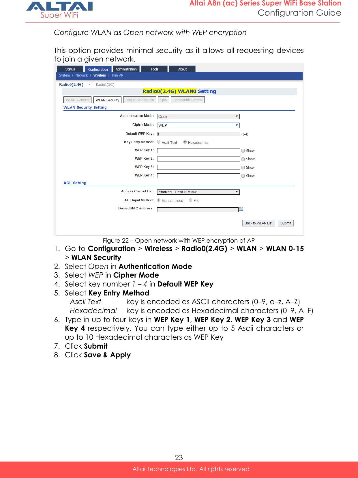
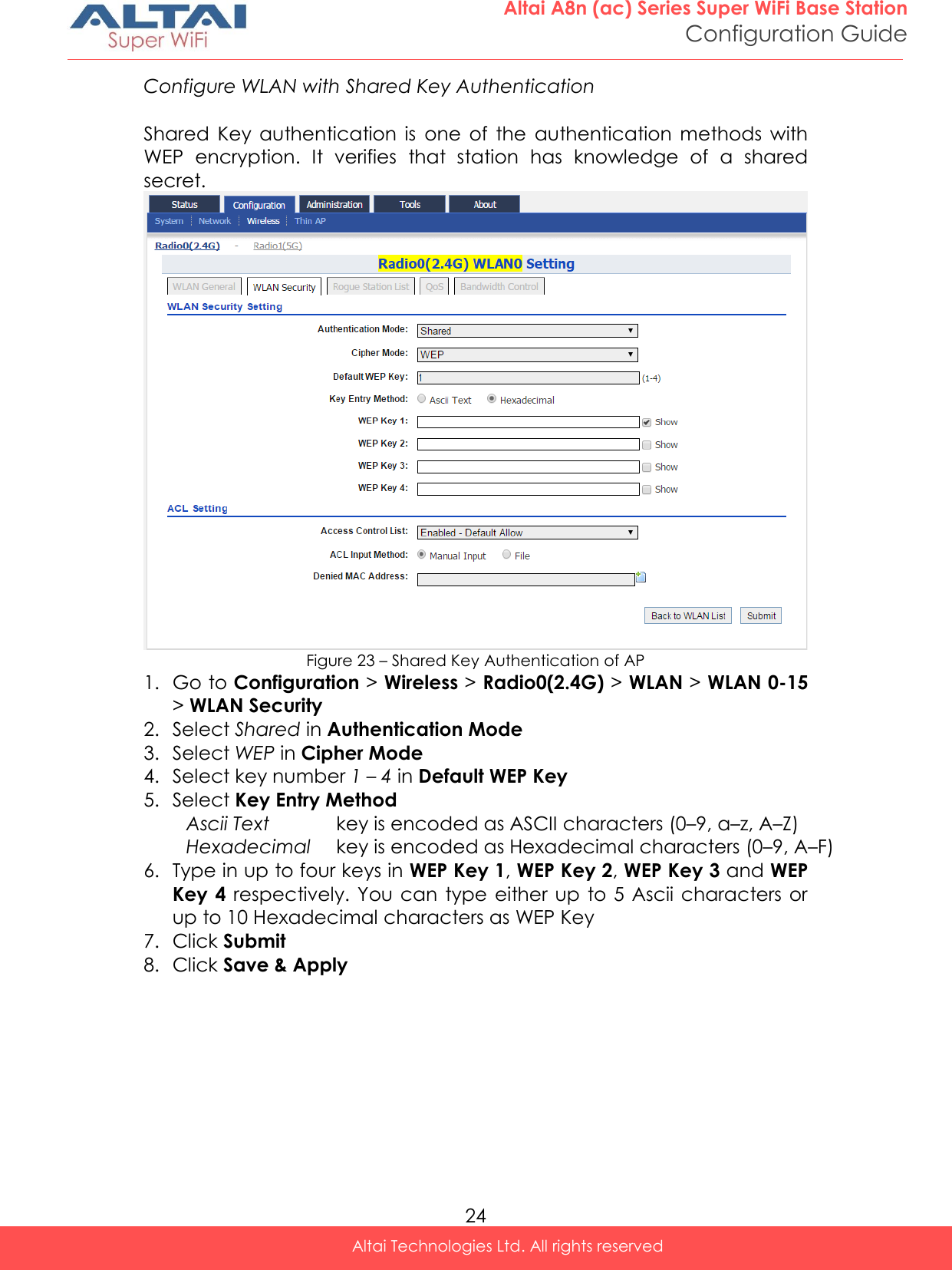
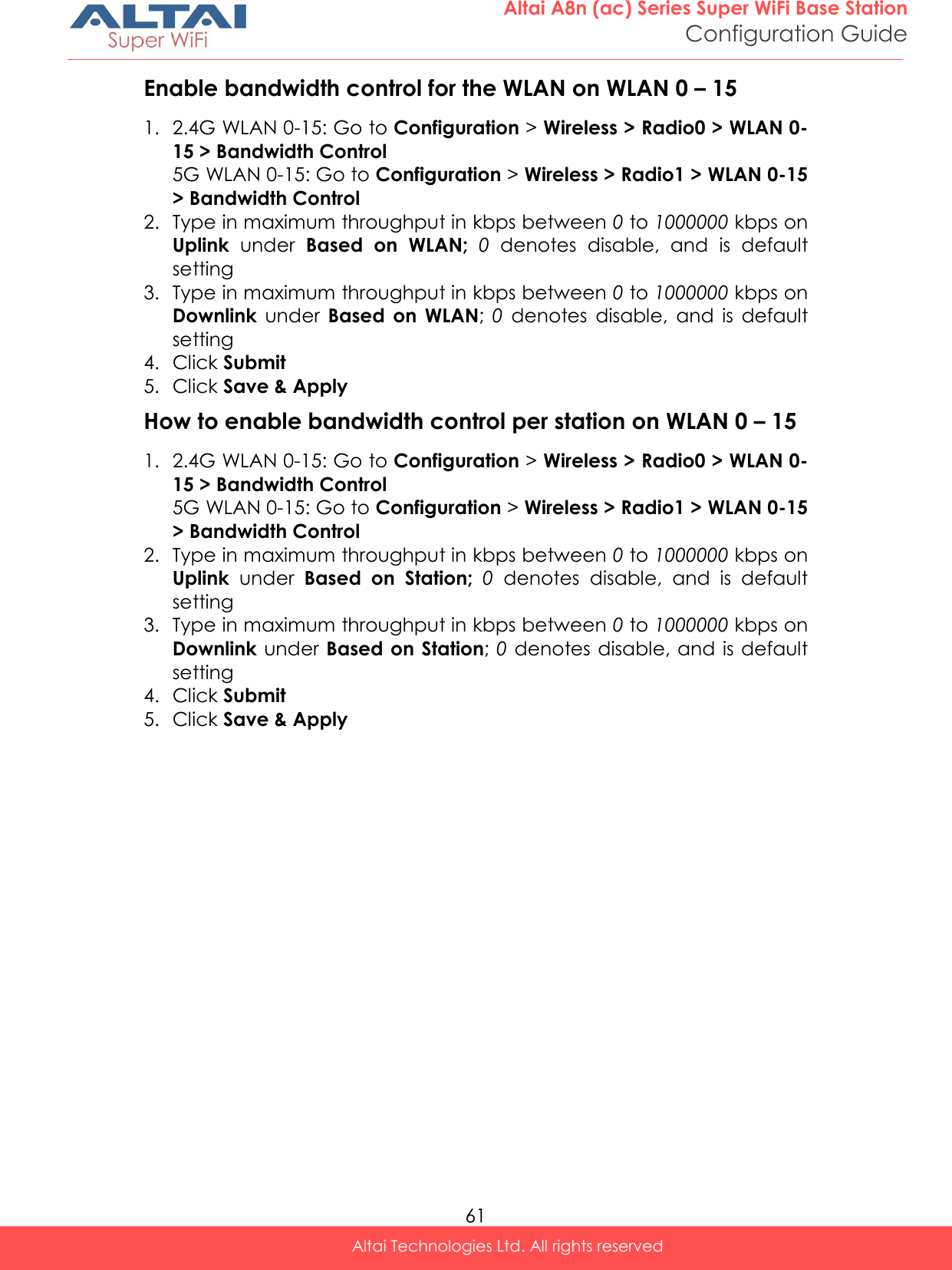
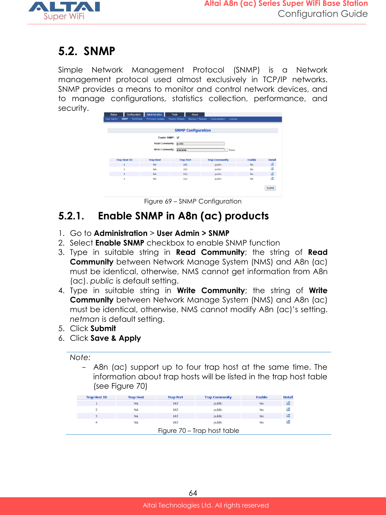
![20 Altai A8n (ac) Series Super WiFi Base Station Configuration Guide Altai Technologies Ltd. All rights reserved WLAN 0-15 General Configuration Figure 19 – WLAN Detail Settings of WLAN 0 of AP 1. Go to Configuration > Wireless > Radio0(2.4G) > WLAN 0-15 > More… 2. Change the following settings: Hide SSID [Optional] – Select the checkbox to hide SSID name from its beacon frame SSID – Provide a unique name for the particular WLAN Note: - If you want to configure the same SSID on two different WLAN; their security setting MUST be different from each other. User Isolation [Optional] – Select the checkbox to block user communication within the same SSID in the AP directly. DHCP Trust Port [Optional] - Deselect the checkbox to prevent illegal DHCP servers offering IP address to DHCP clients via this WLAN. Access Traffic Right – Specify the privilege of associated clients; Full Access Associated client can access Internet and manage AP AP Management Only Associated client can manage AP only, but not able to access the Internet AP Management Disable Associated client can access the Internet, but not able to manage AP Max Clients - Specify the maximum associated clients between 1 and 512 on this WLAN. 512 is the default setting. Note: - Max Clients in WLAN 0 – 15 MUST be smaller than or equal to ( ) the Max Clients setting in 0 Radio General Configuration](https://usermanual.wiki/Altai-Technologies/WA8011NAC-X/User-Guide-2975624-Page-28.png)
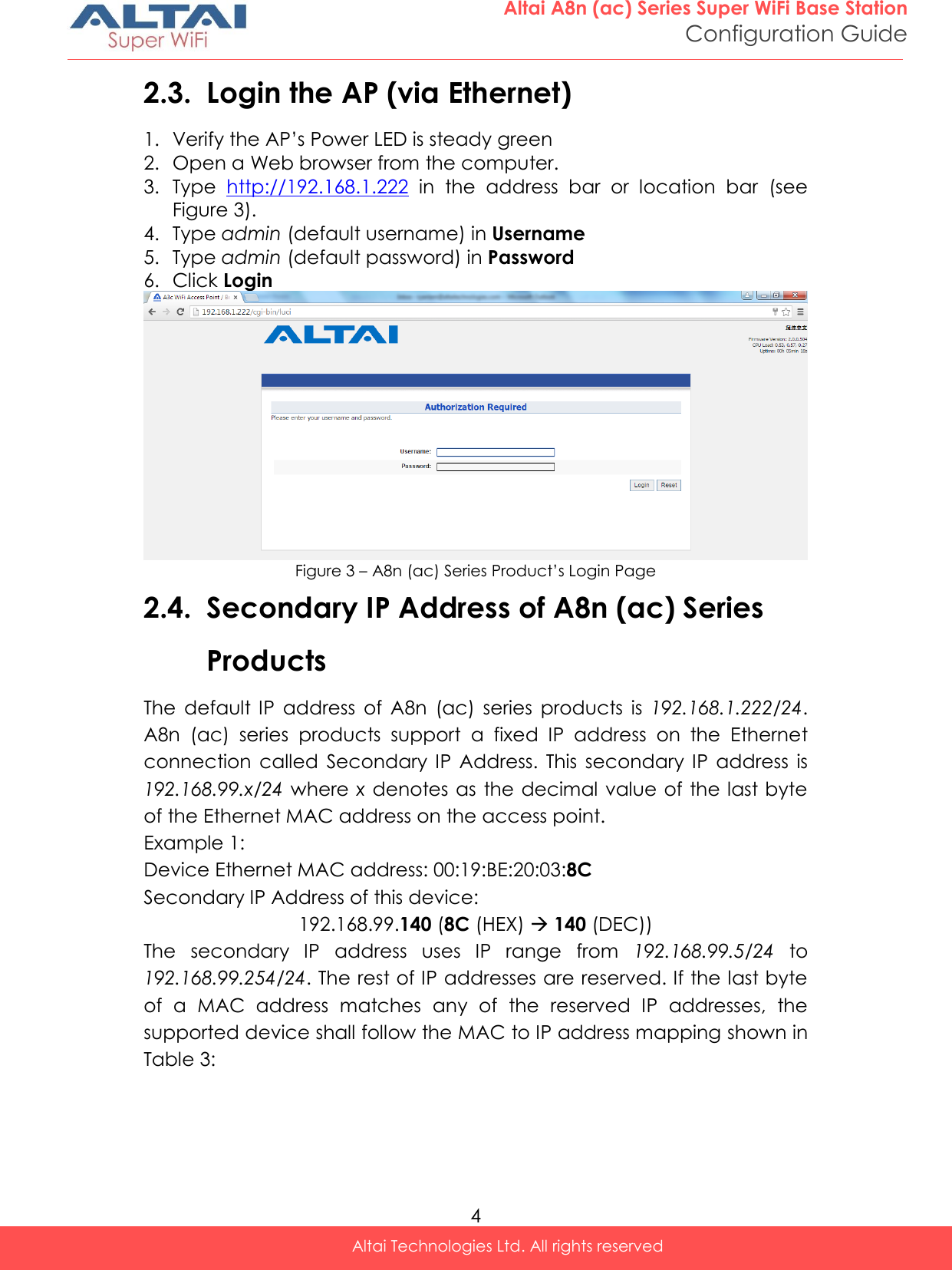
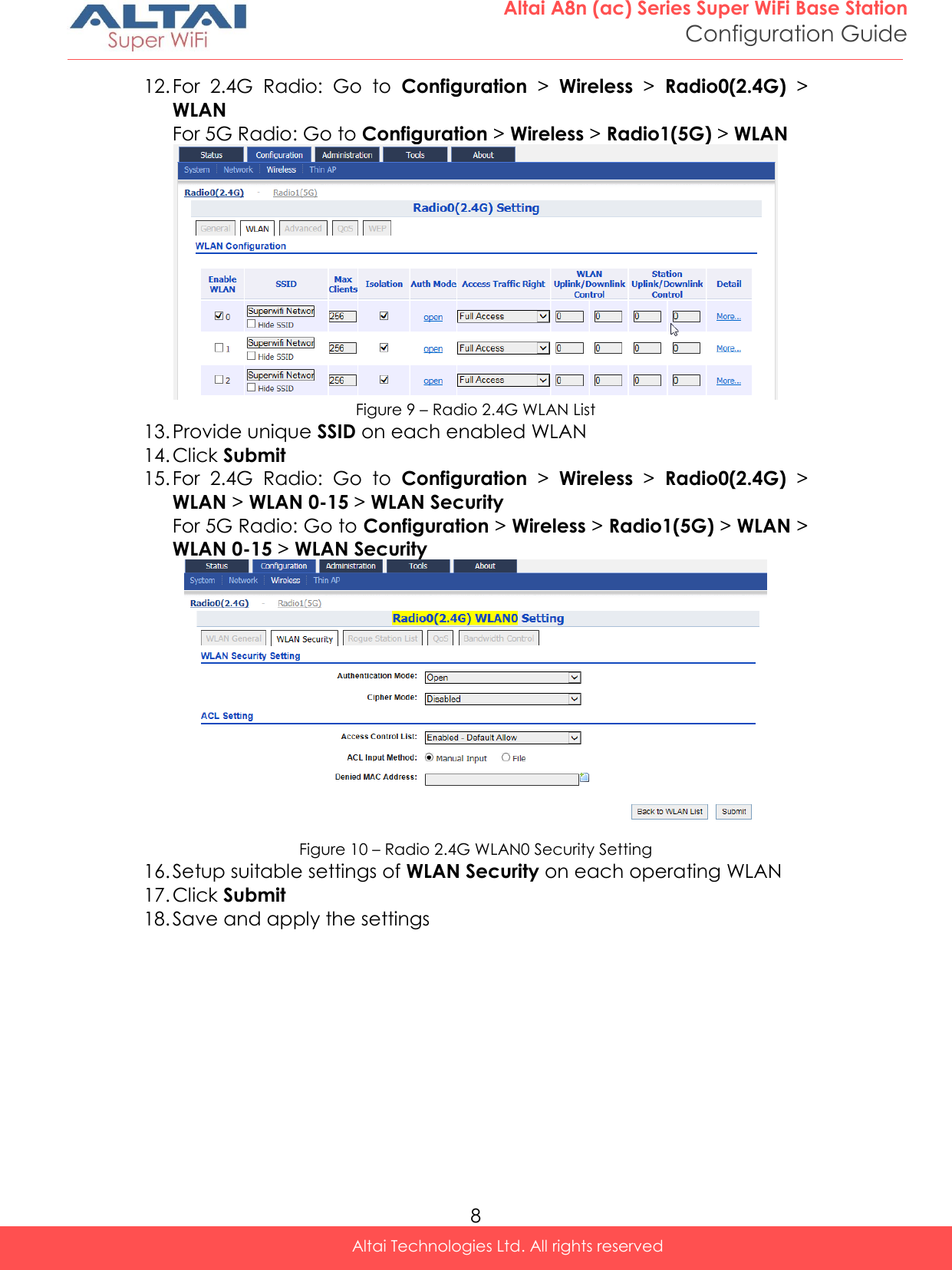
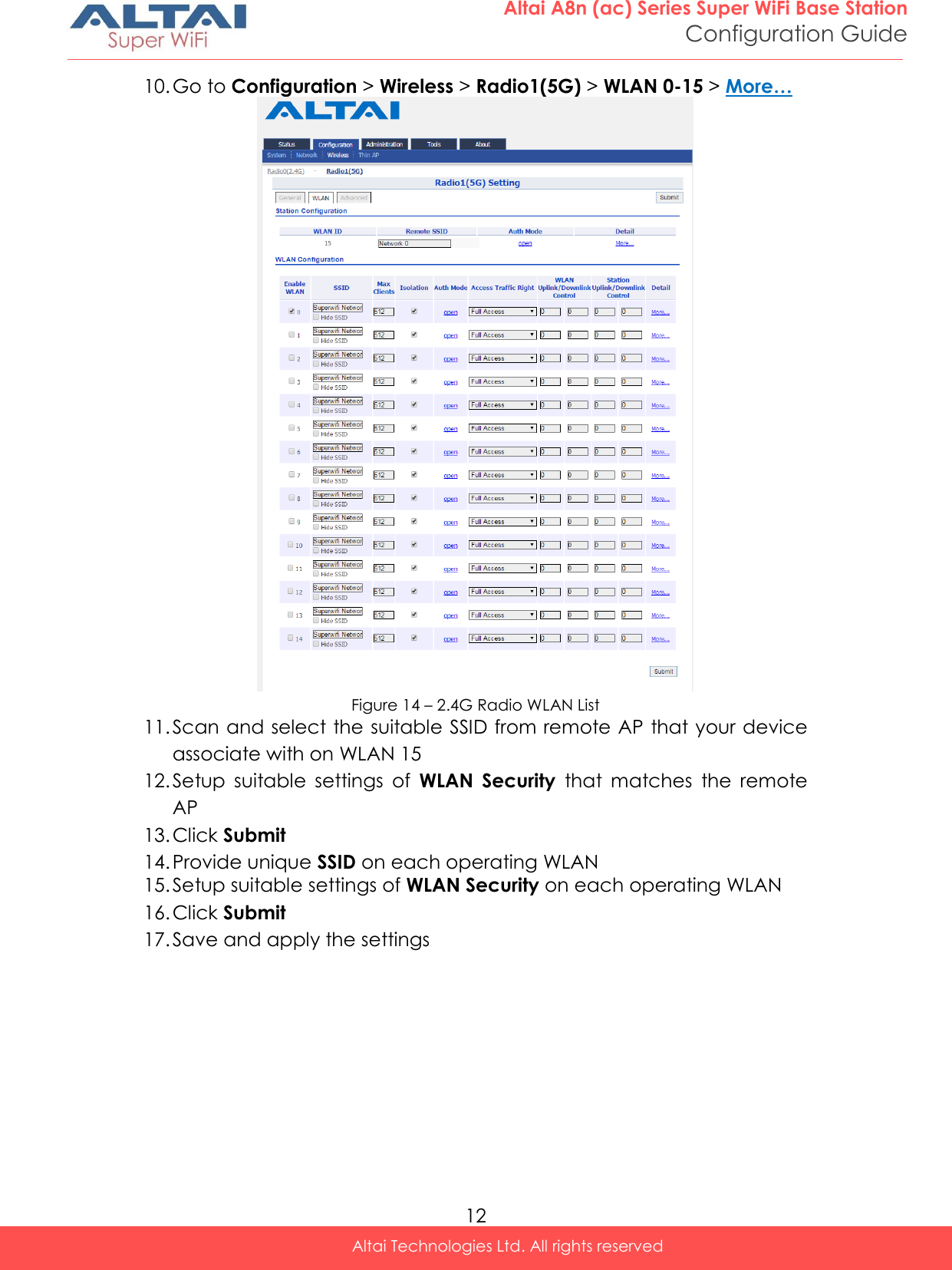
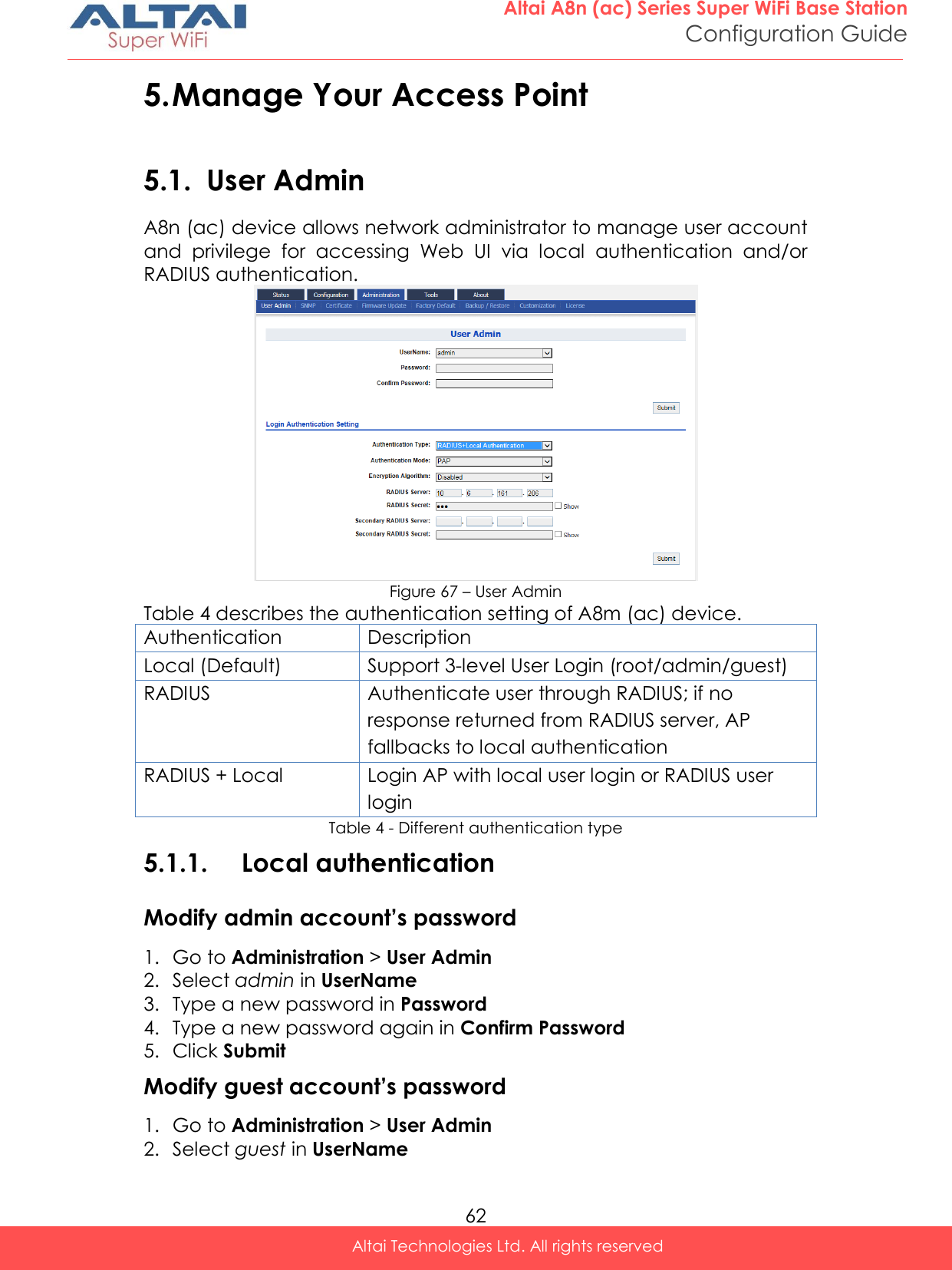
![21 Altai A8n (ac) Series Super WiFi Base Station Configuration Guide Altai Technologies Ltd. All rights reserved Station Association Requirement [Optional] – Specify and additional requirement on Signal Strength to Noise Ratio (SNR) for associated clients. Reject Station Association if SNR less than X dB denote the minimum SNR level which allow clients to associate; You can select any integer between 0dB and 100dB; 0 denotes as disable; 0 is default setting Disassociate Station if SNR drops more than Y dB for consecutive Z packets Y denotes the SNR tolerance; Z denotes the number of consecutive packets their SNR are below the difference of X - Y. Notes: - Example for Station Association Requirement with the following settings: Reject Station Association if SNR less than 30 dB (X = 30); Disassociate Station if SNR drops more than 20 dB for consecutive 10 packets (Y = 20; Z = 10) Consequence: AP accepts the clients to associate if the SNR of packets from the clients is high than (>) 30dB; AP kicks out the associated client if the SNR of 10 consecutive packets is below (<) 10 dB (30 dB – 20 dB) 3. Click Submit 4. Click Save & Apply](https://usermanual.wiki/Altai-Technologies/WA8011NAC-X/User-Guide-2975624-Page-29.png)
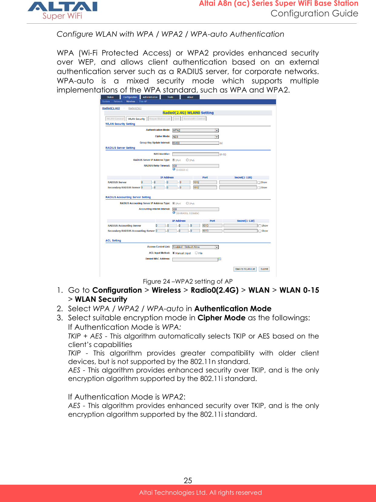
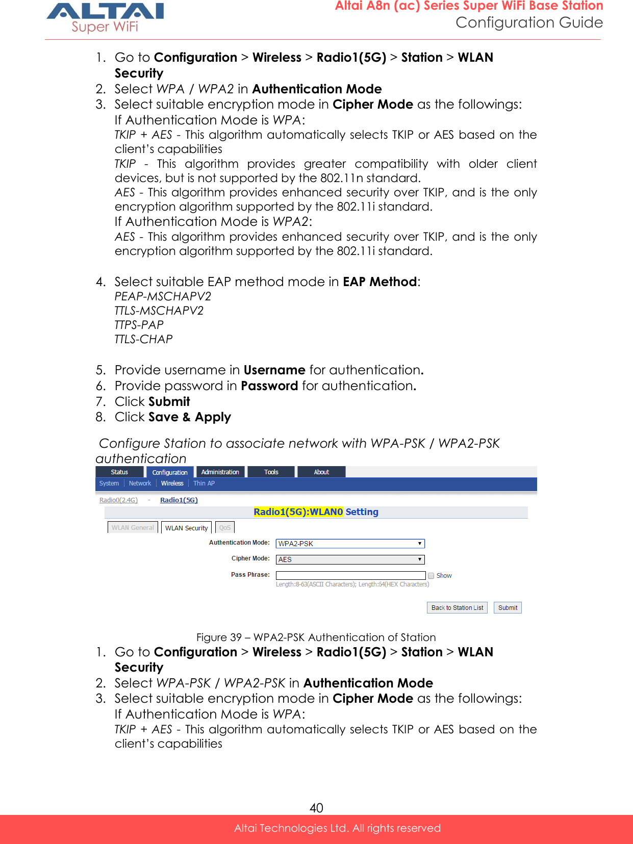
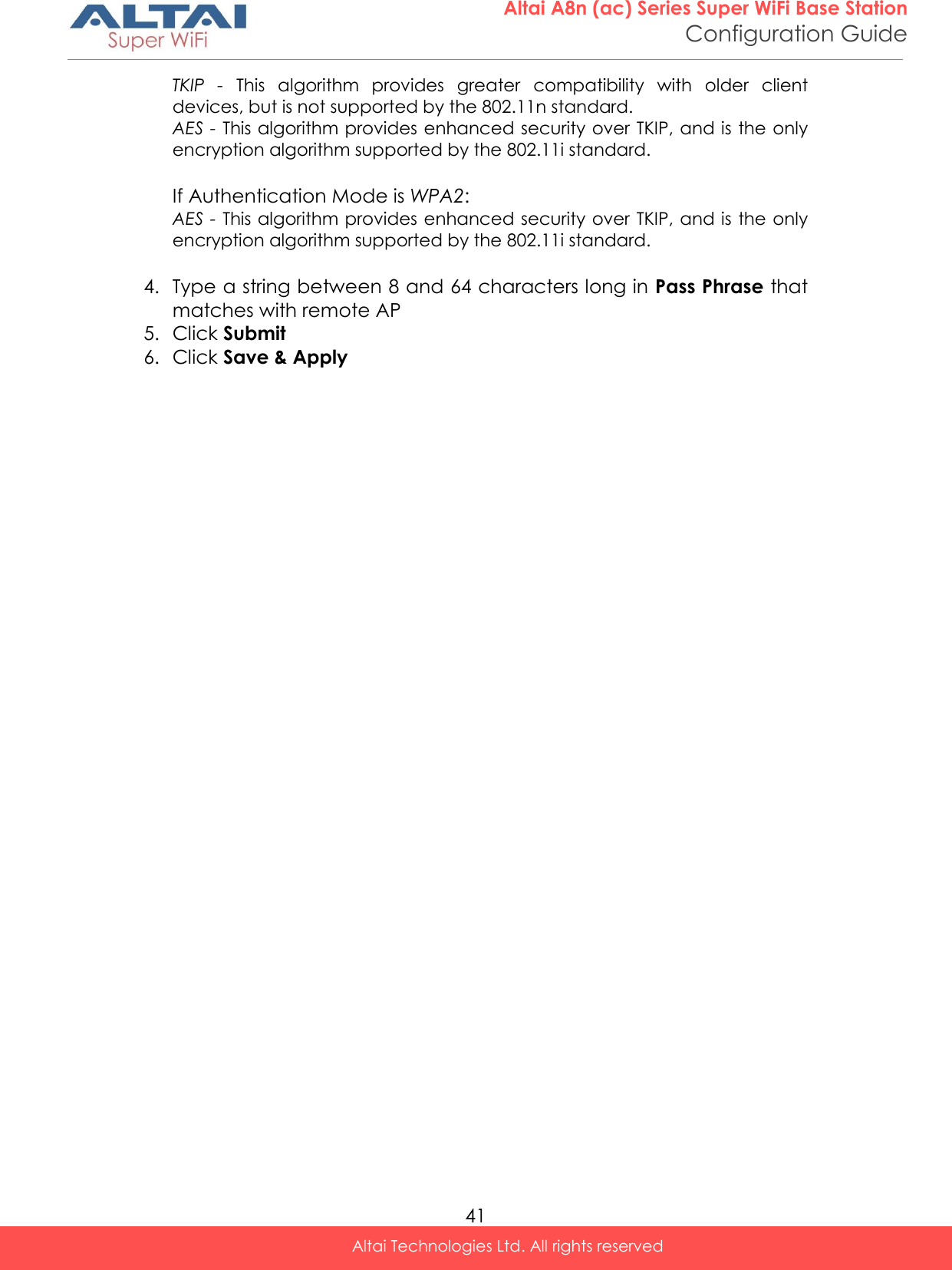
![26 Altai A8n (ac) Series Super WiFi Base Station Configuration Guide Altai Technologies Ltd. All rights reserved If Authentication Mode is WPA-auto: TKIP + AES - This algorithm automatically selects TKIP or AES based on the client’s capabilities Note: - TKIP is not supported by 802.11n standard. If selected TKIP, the 802.11n’s devices will be limited to 802.11g transfer rate, i.e. up to 54 Mbps 4. Provide suitable identification in NAS identifier. Remote RADIUS server use this ID to identify its clients [WPA or WPA2 only] 5. Provide transmission timeout interval between 0 and 86400s in RADIUS Retry Timeout [Optional]. 300 is default setting. 6. Provide IP address of remote RADIUS server for authentication in IP Address of RADIUS Server 7. Provide service port of remote RADIUS server in Port of RADIUS Server. 1812 is default setting. 8. Provide suitable secrets in Secret of RADIUS Server. It is used along with the MD5 hashing algorithm to obfuscate passwords. This secret MUST be as the same as that in RADIUS server. 9. Repeat step 7-9 if the backup RADIUS server is available. 10. RADIUS Accounting Server Setting is optional; you may select if the WLAN requires accounting service from remote RADIUS server. You can change the following settings: Accounting interim Interval - indicates the number of seconds between each interim update in seconds; 300 is default setting. IP Address - IP address of remote RADIUS Accounting Server Port - Service port of remote RADIUS server for accounting service. 1813 is default setting. Secret - Password MUST be as the same as that in RADIUS server 11. Click Submit 12. Click Save & Apply](https://usermanual.wiki/Altai-Technologies/WA8011NAC-X/User-Guide-2975624-Page-34.png)
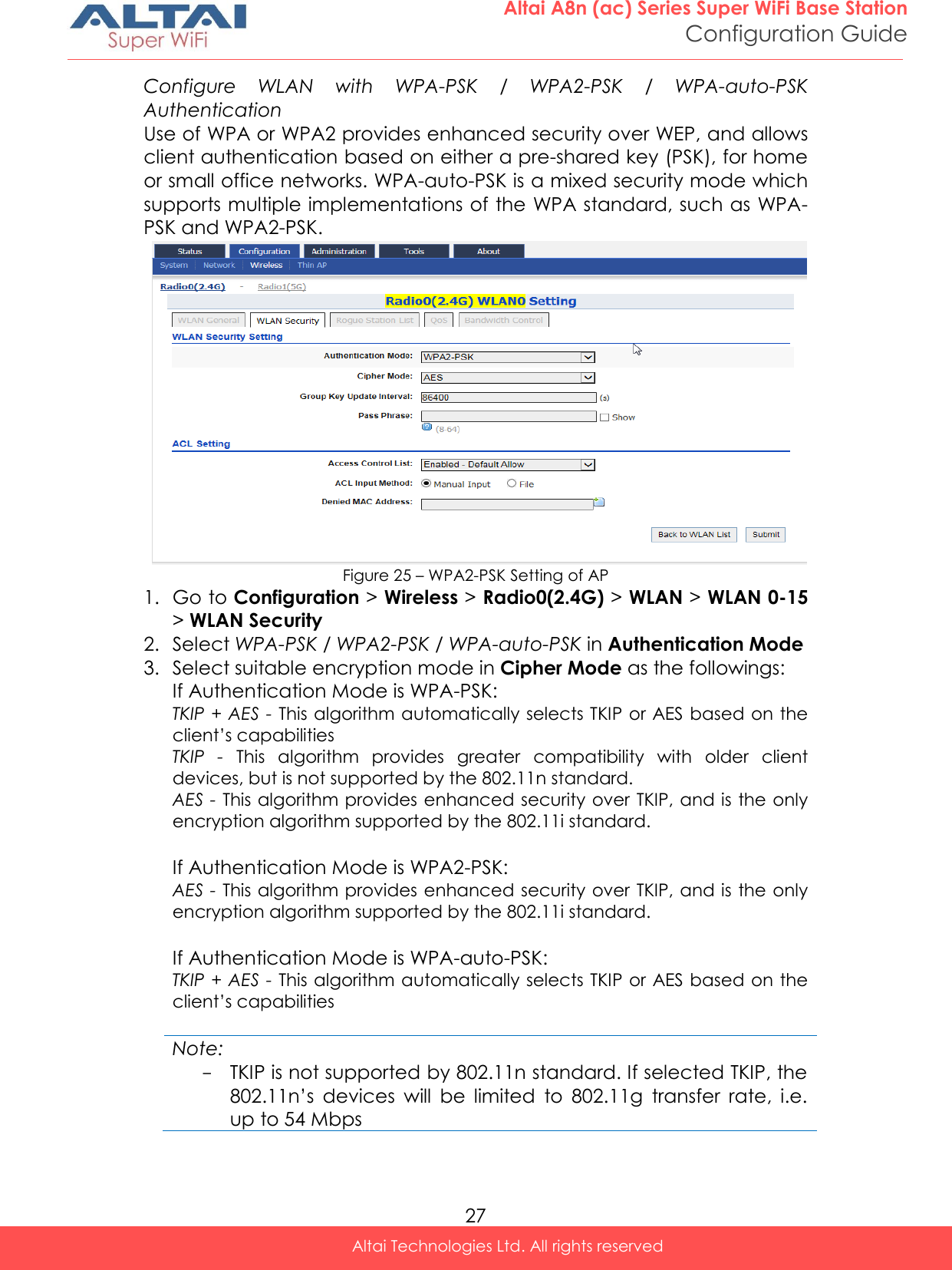
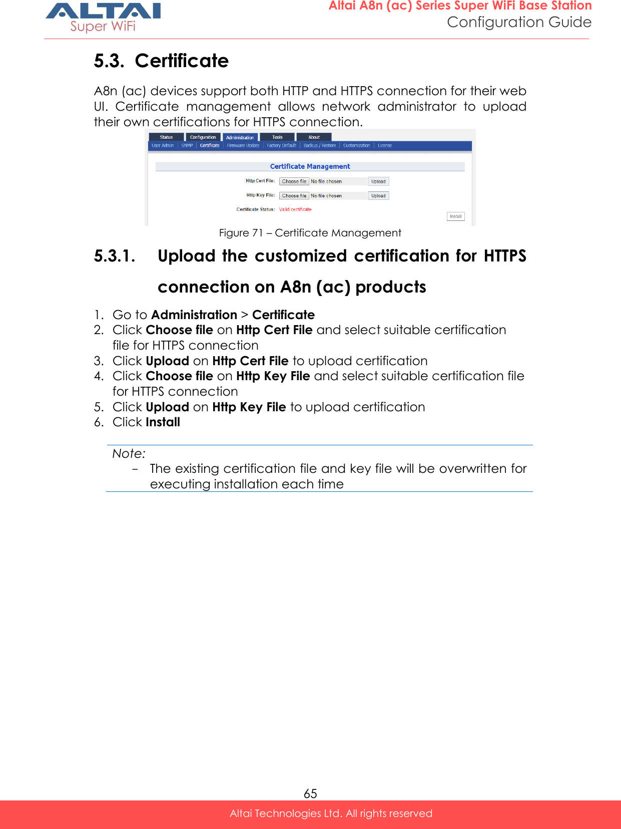
![28 Altai A8n (ac) Series Super WiFi Base Station Configuration Guide Altai Technologies Ltd. All rights reserved 4. Provide time in second in Group Key Update Interval [Optional]. 86400 is default setting. 5. Type in a string between 8 and 64 characters long in Pass Phrase that users will use to connect to the wireless network. 6. Click Submit 7. Click Save & Apply Configure WLAN with WAPI Authentication WLAN Authentication and Privacy Infrastructure (WAPI) is a Chinese National Standard for Wireless LANs (GB 15629.11-2003). Figure 26 – WAPI Settings of AP 1. Go to Configuration > Wireless > Radio0(2.4G) > WLAN > WLAN 0-15 > WLAN Security 2. Select WAPI in Authentication Mode 3. Select SMS4 in Cipher Mode 4. Select suitable option in Certificate Mode: Two-Cert – Wi-Fi client is verified by the certification from authentication server (AS) and Access Point (AP) Three-Cert - Wi-Fi client is verified by the certification from authentication server (AS), access point (AP), and certificate authority (CA) 5. Click Install Certificate; a window for installing certificate is shown (see Figure 27 and Figure 28)](https://usermanual.wiki/Altai-Technologies/WA8011NAC-X/User-Guide-2975624-Page-36.png)
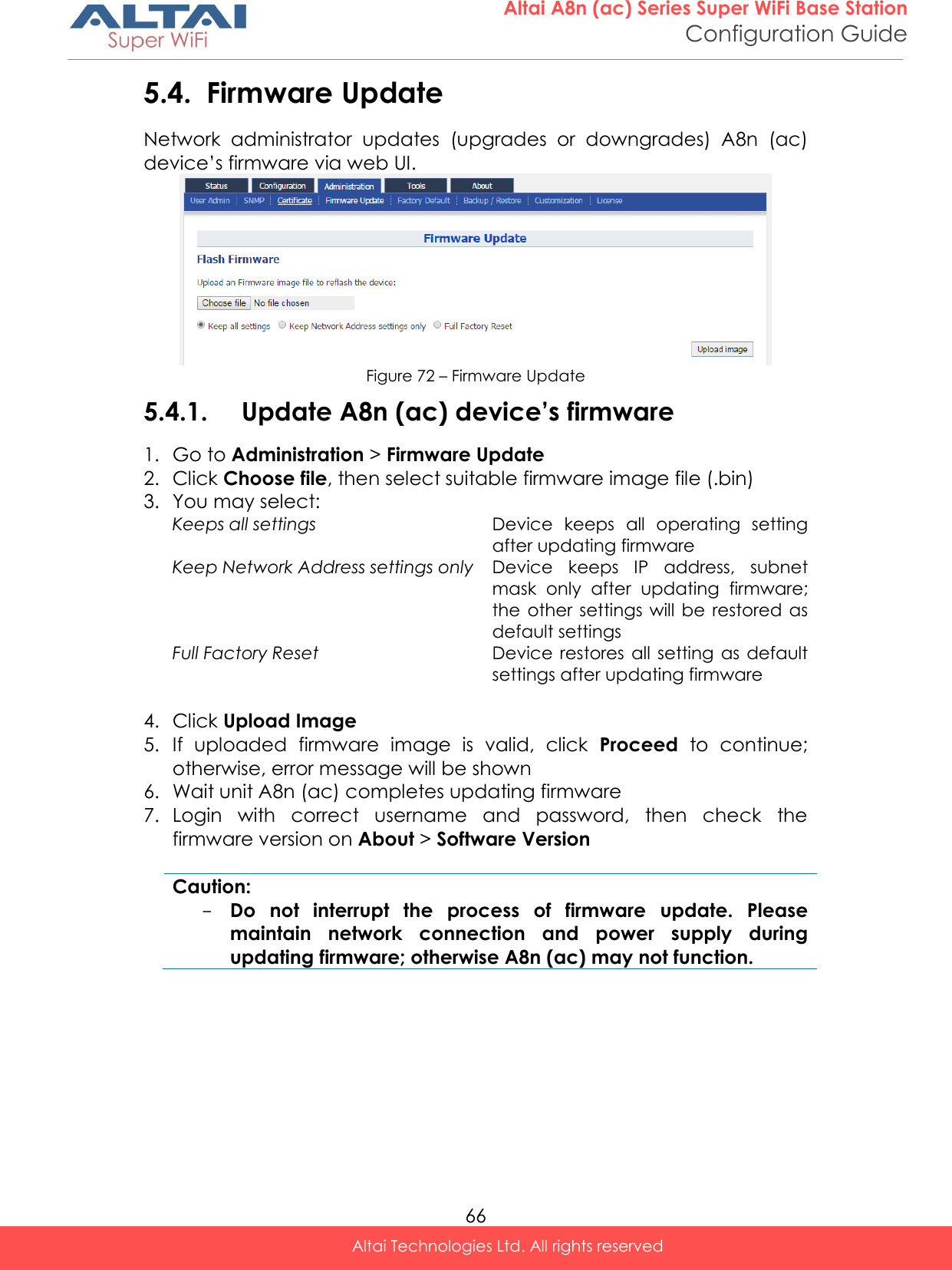
![29 Altai A8n (ac) Series Super WiFi Base Station Configuration Guide Altai Technologies Ltd. All rights reserved Figure 27 – Two-Cert Mode Certification Installation Figure 28 - Three-Cert Mode Certification Installation 6. Click Browse to select suitable certifications 7. Click Upload to upload the selected certifications to A8n (ac) 8. Click Install to install certifications 9. Type IP address of AS server in AS IP Address 10. Type service port of AS server in AS Port 11. Enter interval time between 60 and 2147483647s in Unicast Key Update Interval [Optional]; 86400 is default setting 12. Enter interval time between 60 and 2147483647s in Multicast Key Update Interval [Optional]; 86400 is default setting 13. Click Submit 14. Click Save & Apply](https://usermanual.wiki/Altai-Technologies/WA8011NAC-X/User-Guide-2975624-Page-37.png)
![30 Altai A8n (ac) Series Super WiFi Base Station Configuration Guide Altai Technologies Ltd. All rights reserved Configure WLAN with WAPI-PSK Authentication Figure 29 – WAPI-PSK Setting of AP 1. Go to Configuration > Wireless > Radio0(2.4G) > WLAN > WLAN 0-15 > WLAN Security 2. Select WAPI in Authentication Mode 3. Select SMS4 in Cipher Mode 4. Type in a string between 8 and 64 characters long in Pass Phrase that users will use to connect to the wireless network. 5. Enter interval time between 60 and 2147483647s in Unicast Key Update Interval [Optional]; 86400 is default setting 6. Enter interval time between 60 and 2147483647s in Multicast Key Update Interval [Optional]; 86400 is default setting 7. Click Submit 8. Click Save & Apply](https://usermanual.wiki/Altai-Technologies/WA8011NAC-X/User-Guide-2975624-Page-38.png)
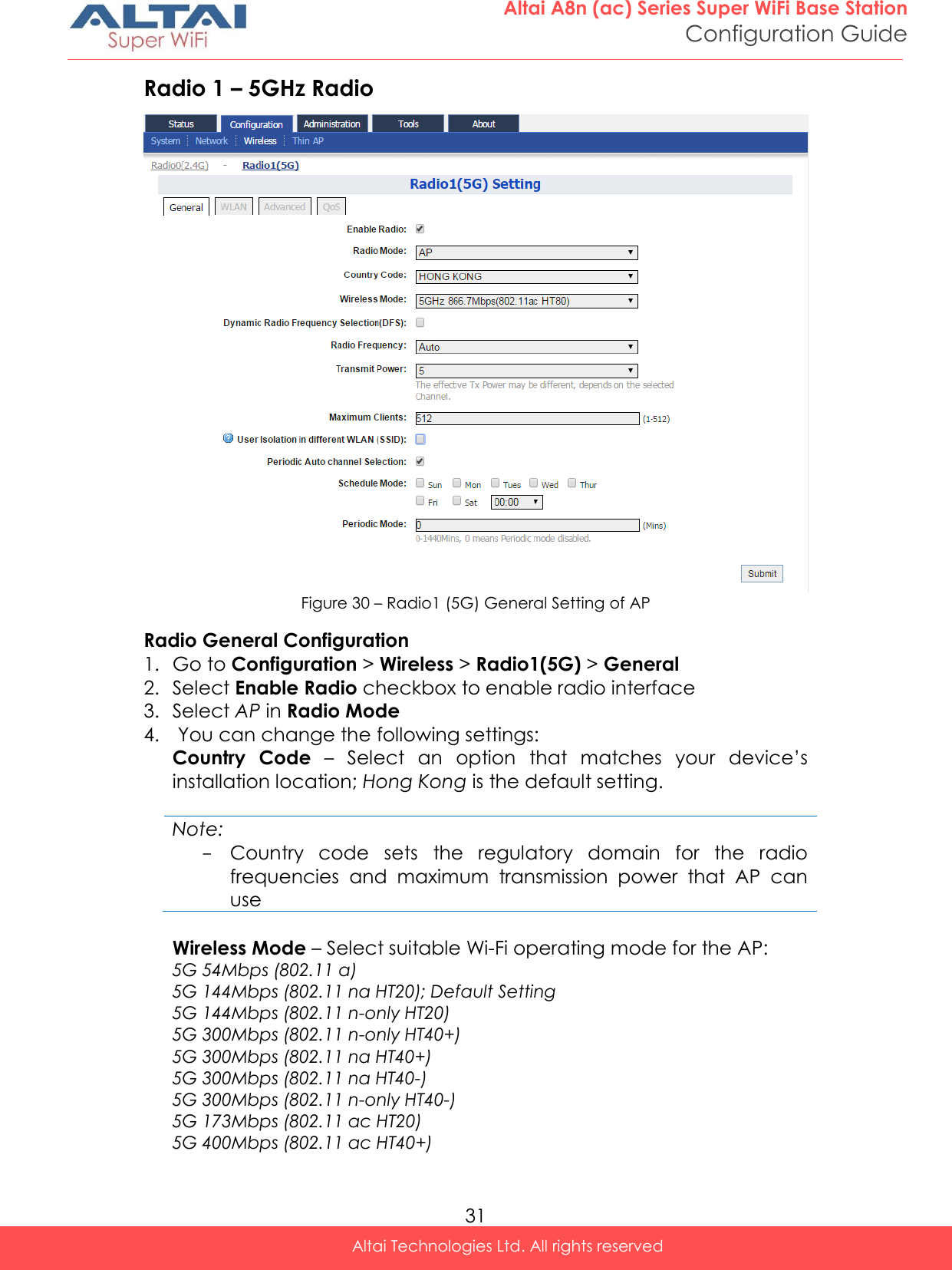
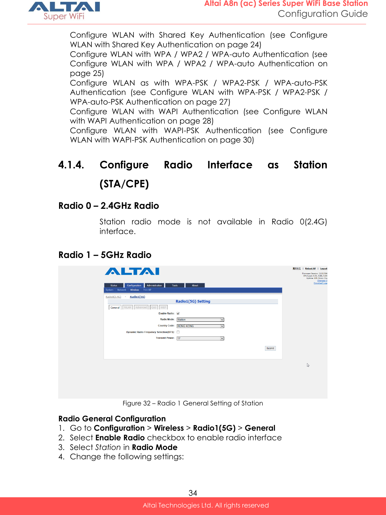
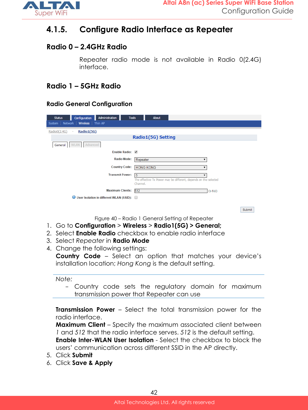
![32 Altai A8n (ac) Series Super WiFi Base Station Configuration Guide Altai Technologies Ltd. All rights reserved 5G 400Mbps (802.11 ac HT40-) 5G 866.7Mbps (802.11 ac HT80) Dynamic Radio Frequency Selection (DFS) – Select to enable automatic channel selection that selects the least congested channel where radar is not detected during booting up. Note: - Radio Frequency is set as auto if DFS is enabled Radio Frequency – Choose the operating channel for the radio interface; AP selects the channel with the least amount of interference if Auto is selected. 5180MHz (Channel 36) is the default setting Transmission Power – Select the total transmission power for the radio interface. Maximum Client [Optional] – Specify the maximum associated client between 1 and 512 that the radio interface serves. 512 is the default setting. Disable HT20/HT40 Auto Switch [Optional] – If select the checkbox, AP will NOT switch the channel width between 20 MHz and 40 MHz automatically. This option is only available if any wireless mode with 802.11n-only/na HT40+/- is selected. User Isolation in different WLAN (SSID): [Optional] - Select the checkbox to block the users’ communication across different SSID in the AP directly. Periodic Auto channel Section [Optional] – Select the checkbox to enable scheduled channel selection task on the radio interface: Schedule Mode Select exact time and day(s) for selecting radio frequency for the interface Periodic Mode Select a countdown timer (minute) for selecting radio frequency for the interface; 0 denotes disable. 5. Click Submit 6. Click Save & Apply](https://usermanual.wiki/Altai-Technologies/WA8011NAC-X/User-Guide-2975624-Page-40.png)

![36 Altai A8n (ac) Series Super WiFi Base Station Configuration Guide Altai Technologies Ltd. All rights reserved Station Configuration Figure 33 - Station Setting 1. Go to Configuration > Wireless > Radio1(5G) > Station > More… 2. Change the following settings: Lock AP Mac [Optional] – Select to force station that associate the AP with MAC address in Remote AP MAC only Remote SSID – Enter the SSID that station is going to associate. You may use [Scan] to look for the surrounding SSID. Figure 34 – SSID scan result - Station](https://usermanual.wiki/Altai-Technologies/WA8011NAC-X/User-Guide-2975624-Page-44.png)
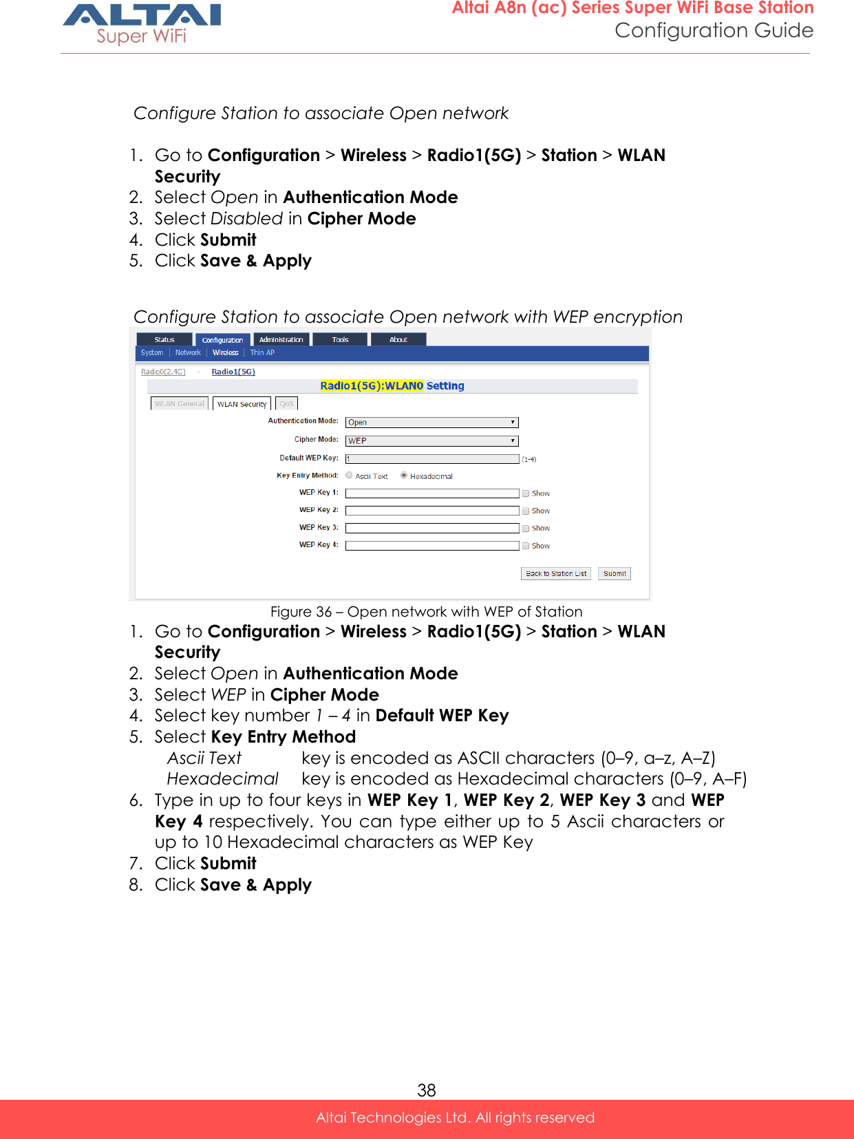
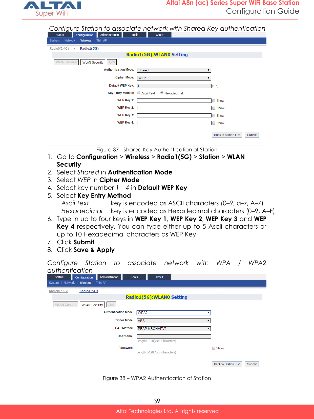
![37 Altai A8n (ac) Series Super WiFi Base Station Configuration Guide Altai Technologies Ltd. All rights reserved Preferred AP0 / AP1 / AP2 Mac [Optional] – Enter up to three AP MAC addresses that station associates them preferentially. AP0 is the highest priority. Roaming Setting [Optional] Enable Roaming - Select to enable roaming on station Scan SNR Threshold – Enter SNR from 0dB to 100dB that station performs channel scanning if the SNR of received signal from associated AP is less than (<) this threshold; 35 is default setting. Roaming SNR Threshold - Enter SNR from 0dB to 100dB that station triggers the roaming if the SNR of received signal from associated AP is less than (<) this threshold; 30 is default setting. Note: - Scan SNR Threshold MUST be larger than (>)Roaming SNR Threshold Max Scan Interval - Specify the maximum duration from 1s to 3600s for channel scanning; 60s is default setting. Min Scan Interval - Specify the minimum duration from 1s to 60s for channel scanning; 10s is default setting Scan SNR Fluctuation Threshold – Enter SNR from 0dB to 10dB; the current AP's signal fluctuation (compared with previous scan result) is higher than (>) this threshold, the station will do scanning. 5dB is default setting. Roaming Hysteresis – Select to enable that station will be stickier to current associated AP. Scan Channel List – Select the particular channel for scan 3. Click Submit 4. Click Save & Apply Station Security Configuration Figure 35 – Security Settings of Station](https://usermanual.wiki/Altai-Technologies/WA8011NAC-X/User-Guide-2975624-Page-45.png)
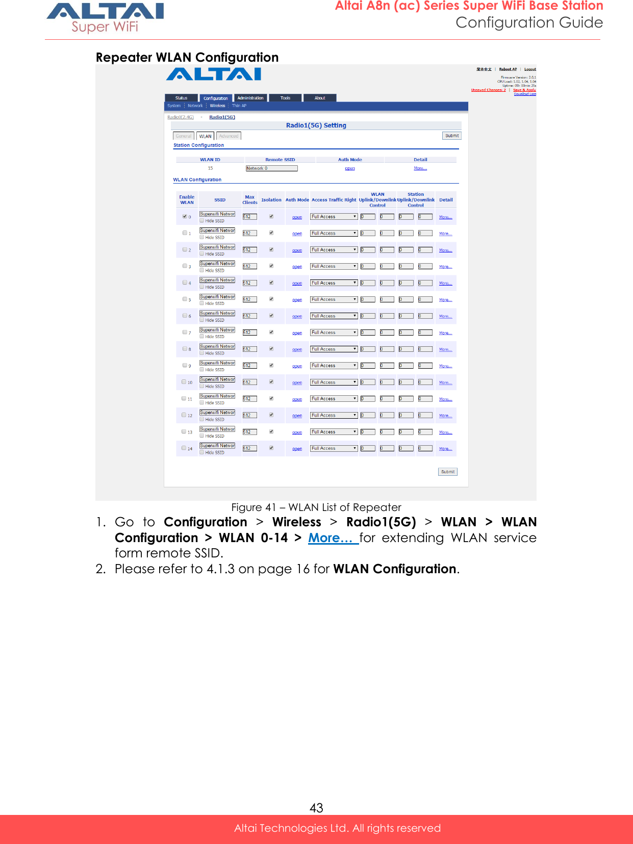
![47 Altai A8n (ac) Series Super WiFi Base Station Configuration Guide Altai Technologies Ltd. All rights reserved 4.2.6. Configure AP as IP Gateway Figure 46 – Gateway Settings 1. Go to Configuration > Network > General 2. Select Gateway in Network Setting 3. Change the followings on WAN setting: Internet Connection Type – Set AP as a client with fixed IP address or DCHP client: Static Stand for Static IP addressing; AP will not update its IP address automatically DHCP Client Require an IP address from DCHP server on the network; AP renews its IP address periodically IPv4 Address – Type in an IP address for AP (Static Internet Connection Type only) IPv4 Subnet Mask – Type in a subnet mask for AP (Static Internet Connection Type only) IPv4 Default Gateway – Type in an IP address of default gateway for AP (Static Internet Connection Type only) IPv4 DNS Server – Type in one or more DNS server for AP (Static Internet Connection Type only). 4. Change the followings on LAN setting: LAN IP Address – Provide an IP address on LAN interface of device LAN IP Address Subnet Mask – Provide a subnet mask on LAN interface of device 5. Assign enabled interfaces into WAN group or LAN group in WAN/LAN Interface Assignment; all interfaces in the same group work as bridge 6. Select Enable NAT Mode to enable NAT in AP [Optional] 7. Click Submit 8. Click Save & Apply](https://usermanual.wiki/Altai-Technologies/WA8011NAC-X/User-Guide-2975624-Page-55.png)
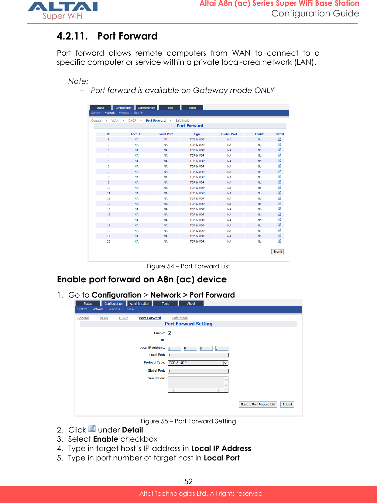
![53 Altai A8n (ac) Series Super WiFi Base Station Configuration Guide Altai Technologies Ltd. All rights reserved 6. Select suitable protocol in Protocol Type: TCP & UDP TCP UDP 7. Type in port number of AP in Global Port 8. Type in description in Description [Optional] 9. Click Submit 10. Click Save & Apply 4.2.12. Safe Mode Safe Mode is for detecting the backhaul link integrity. If the AP loses its backhaul connectivity, it forces the clients to re-associate with another AP by changing its SSID to a default Safe Mode_X, where X is the MAC address of the radio interface in hexadecimal. This action can protect the client from connecting to the AP which has no backhaul to the Internet end. Total duration for AP from losing backhaul link to safe mode is 3 x ping interval seconds. Note: - A8n (ac) recovers itself from safe mode if it detects the backhaul link is recovered Figure 56 – Safe Mode Setting Enable safe mode on A8n (ac) device 1. Go to Configuration > Network > Safe Mode 2. Select Enable Safe Mode checkbox 3. Type in at least one IP address of remote host in Ping Host 1 / Ping Host 2 / Ping Host 3 4. Type in interval time between 3s and 30s in Ping Interval 5. Click Submit 6. Click Save & Apply](https://usermanual.wiki/Altai-Technologies/WA8011NAC-X/User-Guide-2975624-Page-61.png)

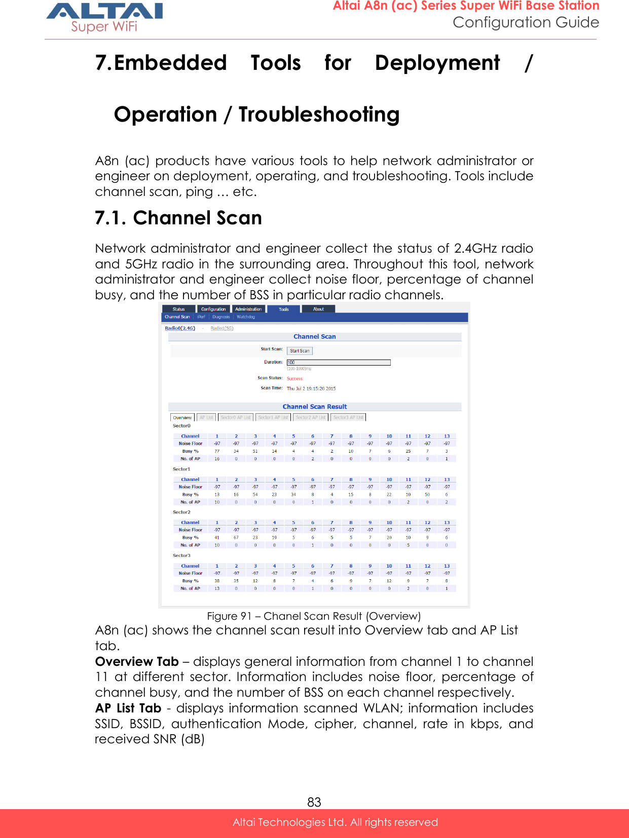
![84 Altai A8n (ac) Series Super WiFi Base Station Configuration Guide Altai Technologies Ltd. All rights reserved Sector X AP List Tab– displays information scanned WLAN in sector 0 – 4. X is the sector number. Information includes SSID, BSSID, authentication Mode, cipher, channel, rate in kbps, and received SNR (dB) 7.1.1. Perform channel scan on 2.4G radio 1. Go to Tools > Channel Scan > Radio 0 (2.4G) 2. [Optional] Provide channel scan interval from 100ms to 1000ms in Duration 3. Click Start Scan 4. Wait until Scan Status is changed from In Process to Success; it will take for 20 seconds approximately Note: - Wi-Fi service will be interrupted during channel scan 7.1.2. Perform channel scan on 5G radio 1. Go to Tools > Channel Scan > Radio 1 (5G) 2. [Optional] Provide channel scan interval from 100ms to 1000ms in Duration 3. Click Start Scan 4. Wait until Scan Status is changed from In Process to Success; it will take for 20 seconds approximately Note: - Wi-Fi service will be interrupted during channel scan 7.2. iPerf A8n (ac) Series products embed iPerf server tool. Network Administrator / Engineer can test the throughput performance via Ethernet, Radio0, or Radio1 with this built-in tool. Figure 92 – iPerf Server Configuration](https://usermanual.wiki/Altai-Technologies/WA8011NAC-X/User-Guide-2975624-Page-92.png)
![85 Altai A8n (ac) Series Super WiFi Base Station Configuration Guide Altai Technologies Ltd. All rights reserved 7.2.1. Enable iPerf TCP Server Figure 93 – iPerf TCP Server Setting 1. Go to Tools > iPerf 2. Click of either Sever ID 1 or Sever ID 2 3. Click Enable Server checkbox to enable iPerf TCP Server 4. Click TCP Server checkbox 5. Specify the listening port between 0 and 65535 on Port [Optional] 6. Click Submit 7. Click Save & Apply 7.2.2. Enable iPerf UDP Server Figure 94 – iPerf UDP Server Setting 1. Go to Tools > iPerf 2. Click of either Sever ID 1 or Sever ID 2 3. Click Enable Server checkbox to enable iPerf UDP Server 4. Click UDP Server checkbox 5. Specify the listening port between 0 and 65535 on Port [Optional] 6. Click Submit 7. Click Save & Apply](https://usermanual.wiki/Altai-Technologies/WA8011NAC-X/User-Guide-2975624-Page-93.png)
![86 Altai A8n (ac) Series Super WiFi Base Station Configuration Guide Altai Technologies Ltd. All rights reserved 7.3. Diagnosis 7.3.1. Ping Test Network administrator and engineer test the reachability of a host and measures the round-trip time between A8n (ac) and the host over an Internet Protocol (IP) network by using ping tool. Figure 95 – Ping Test 7.3.2. Perform ping test 1. Go to Tools > Diagnosis > Ping 2. Type target IP address / host name in Ping IP Address/Host Name 3. [Optional] Specify how many ICMP (ping) packet that A8n (ac) sends to the target host in Packet Count; 4 is default setting 4. [Optional] Specify the packet size of ICMP packet in Packet Size; 56 is default setting 5. Click Start 6. Click Stop to terminate ping test if necessary 7.3.3. Traceroute Test Network administrator tests the route (path) and measuring transit delays of packets across an Internet Protocol (IP) network by using traceroute test.](https://usermanual.wiki/Altai-Technologies/WA8011NAC-X/User-Guide-2975624-Page-94.png)
![87 Altai A8n (ac) Series Super WiFi Base Station Configuration Guide Altai Technologies Ltd. All rights reserved Figure 96 – Traceroute Test How to perform traceroute test 1. Go to Tools > Diagnosis > traceroute 2. Type target IP address / host name in Destination IP Address/Host Name 3. [Optional] Click Enable Resolve IP addresses checkbox to enable IP address to domain name translation 4. [Optional] Specify timeout interval between 1s and 100s in Timeout for traceroute test 5. [Optional] Specify TTL value between 1 and 100 in Pings Per TTL; 3 is default setting 6. [Optional] Specify TTL value between 1 and 100 in Maximum TTL; 30 is default setting 7. Click Start 8. Click Stop to terminate ping test if necessary 7.3.4. Tcpdump A8n (ac) provides a tool to capture packets that passing through a particular interface. It helps network administrator for troubleshooting. Figure 97 – Tcpdump Tool How to perform packet capture on A8n (ac)’s interface 1. Go to Tools > Diagnosis > Tcpdump 2. Select suitable interface in Interface](https://usermanual.wiki/Altai-Technologies/WA8011NAC-X/User-Guide-2975624-Page-95.png)
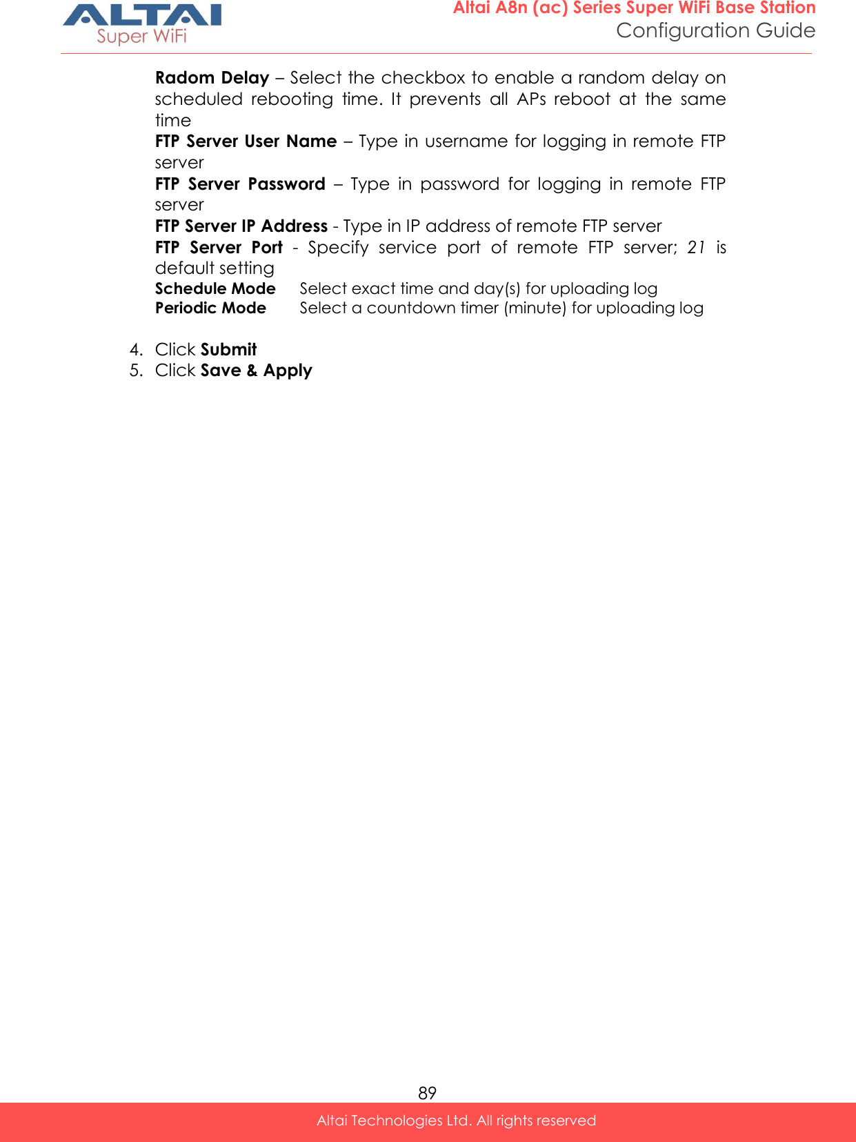
![88 Altai A8n (ac) Series Super WiFi Base Station Configuration Guide Altai Technologies Ltd. All rights reserved 3. [Optional] Specify maximum number of packet in Packet Count 4. [Optional] Specify maximum file size in Capture File Size 5. Click Start 6. Click Stop to terminate ping test if necessary 7. Download capture file after finished. 7.4. Watchdog Watchdog is an electronic timer that is used to detect and recover from system malfunctions. That is timer for periodic reboot. 7.4.1. Schedule Reboot Figure 98 – Schedule Root Enable periodic reboot 1. Go to Tools > Watchdog > Schedule Reboot 2. Click Periodic Reboot to enable reboot scheduler 3. You may change the following settings: Radom Delay – Select the checkbox to enable a random delay on scheduled rebooting time. It prevents all APs reboot at the same time Schedule Mode Select exact time and day(s) for rebooting device Periodic Mode Select a countdown timer (minute) for rebooting device 4. Click Submit 5. Click Save & Apply Enable periodic log upload 1. Go to Tools > Watchdog > Schedule Reboot 2. Click Periodic Upload Log to enable upload log scheduler 3. You may change the following settings:](https://usermanual.wiki/Altai-Technologies/WA8011NAC-X/User-Guide-2975624-Page-96.png)
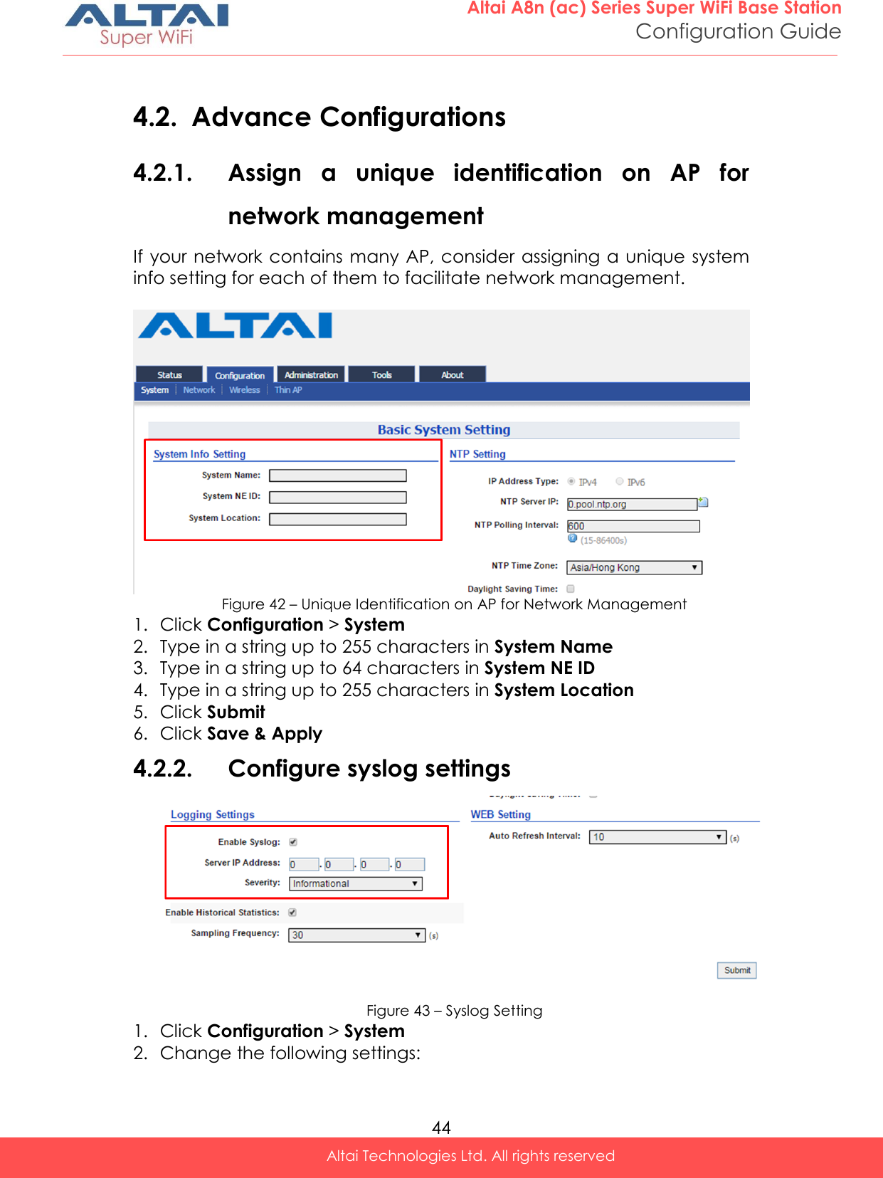
![90 Altai A8n (ac) Series Super WiFi Base Station Configuration Guide Altai Technologies Ltd. All rights reserved 7.4.2. Ping Watchdog Ping watchdog is mechanism that A8n (ac) reboots itself if it fails to communicate (ping) to target host for serval time. Figure 99 – Ping Watchdog Enable ping watchdog 1. Go to Tools > Watchdog > Ping watchdog 2. Click Enable Ping Watchdog to enable this function 3. Type in IP address of target host in IP Address To Ping 4. [Optional] Specify interval between each ICMP request in Ping Interval; 300 is default setting 5. [Optional] Specify delay time of each ICMP request in Startup Delay; 300 is default setting 6. [Optional] Specify fail tolerant in Failure Count to Reboot; 3 is default setting 7. Click Submit 8. Click Save & Apply](https://usermanual.wiki/Altai-Technologies/WA8011NAC-X/User-Guide-2975624-Page-98.png)