Altai Technologies WA8011NAC Altai A8-Ein (ac) Super WiFi Base Station User Manual A3 Series Configuration Manual
Altai Technologies Limited Altai A8-Ein (ac) Super WiFi Base Station A3 Series Configuration Manual
Contents
- 1. Users Manual - Installation
- 2. Users Manual - Configuration
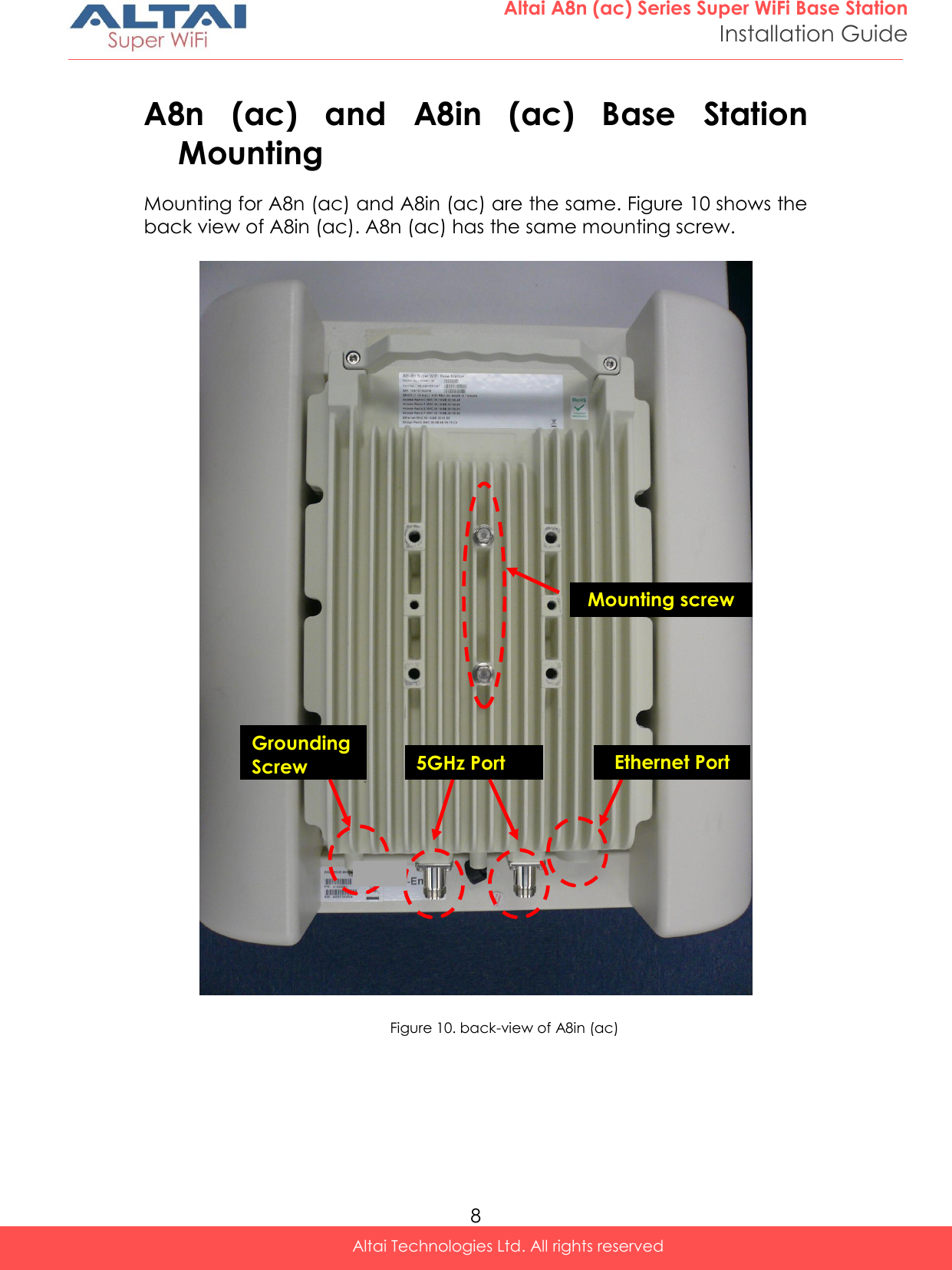
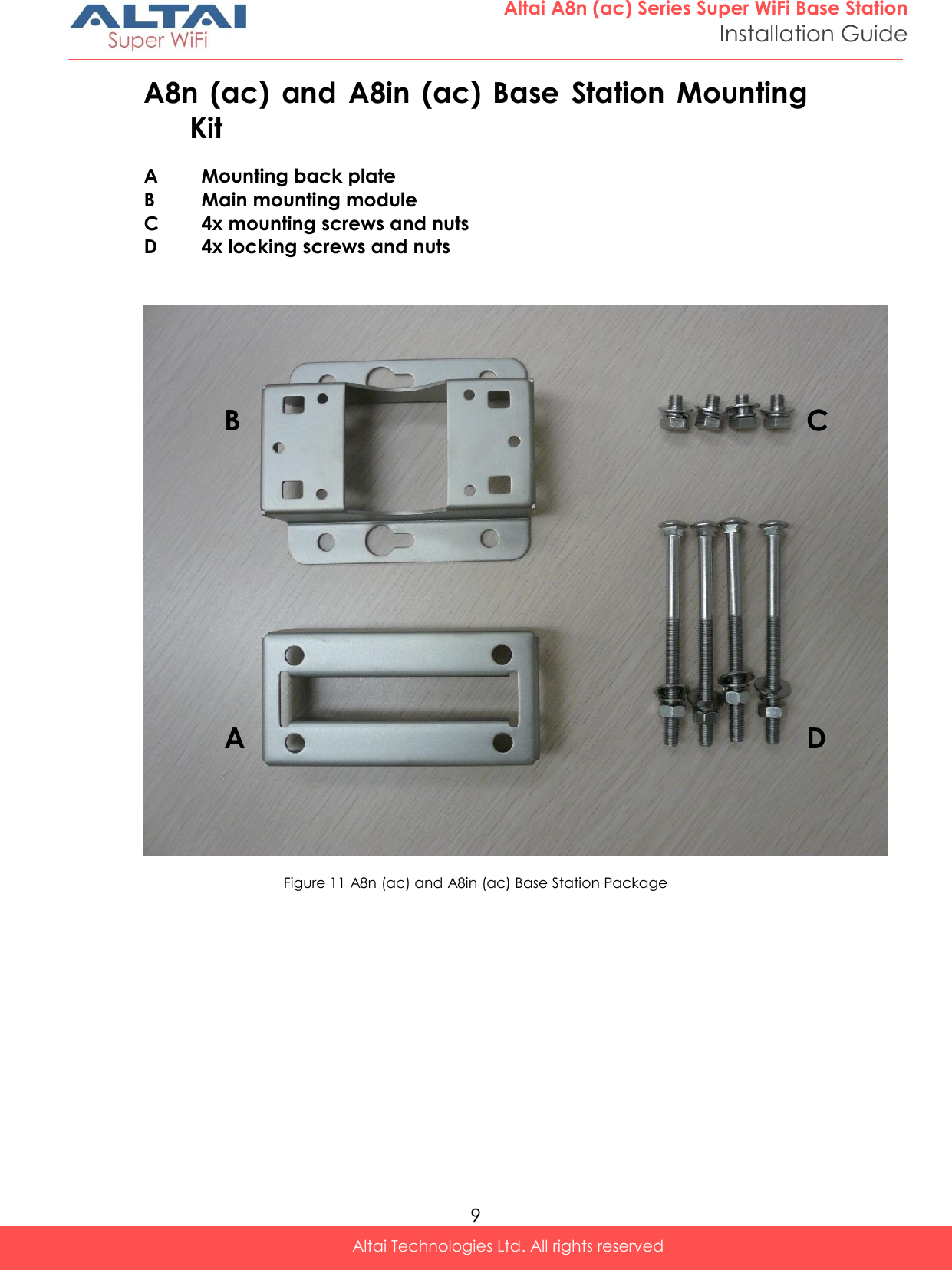
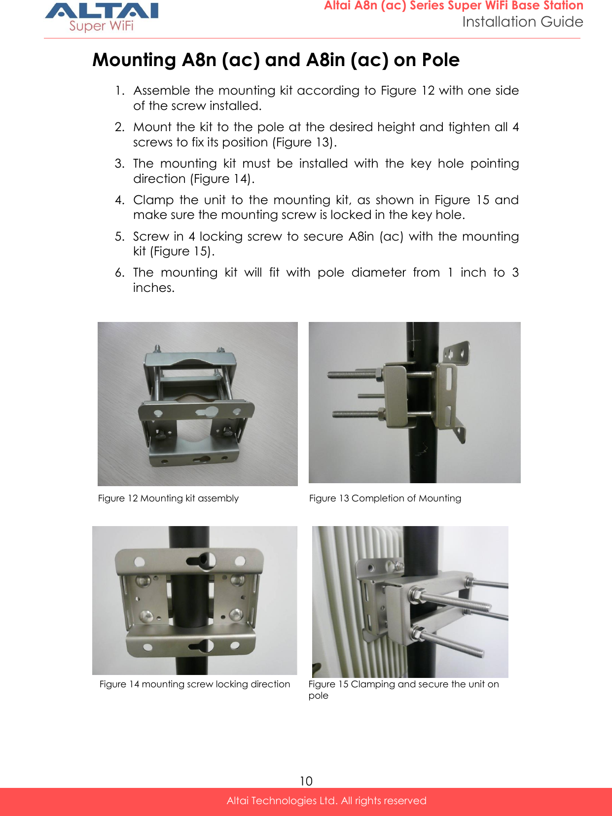
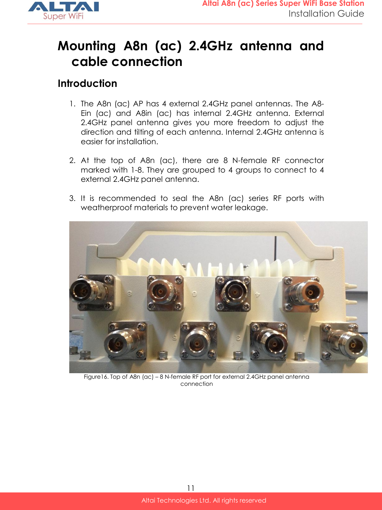
Users Manual - Installation


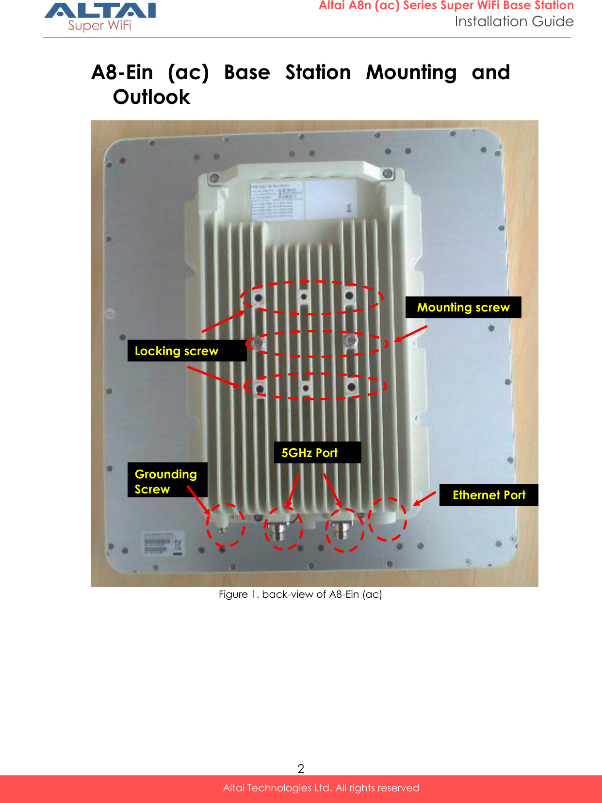
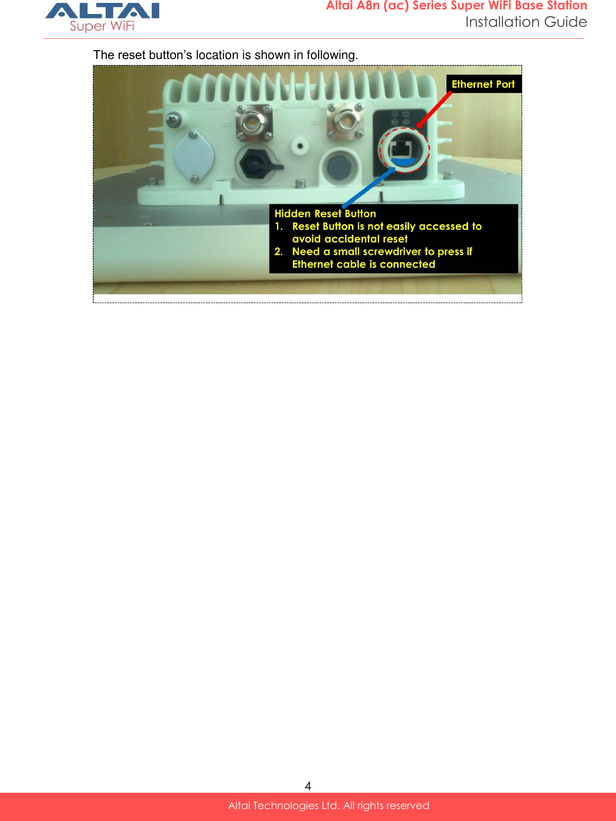
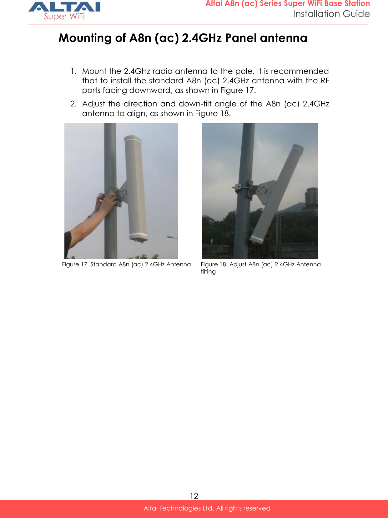
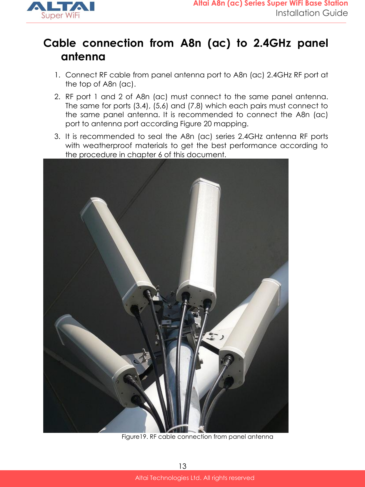
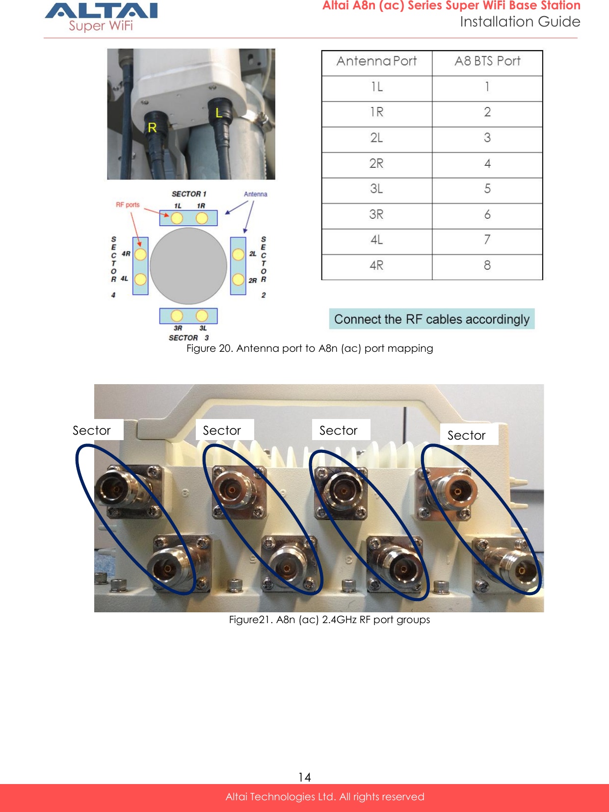
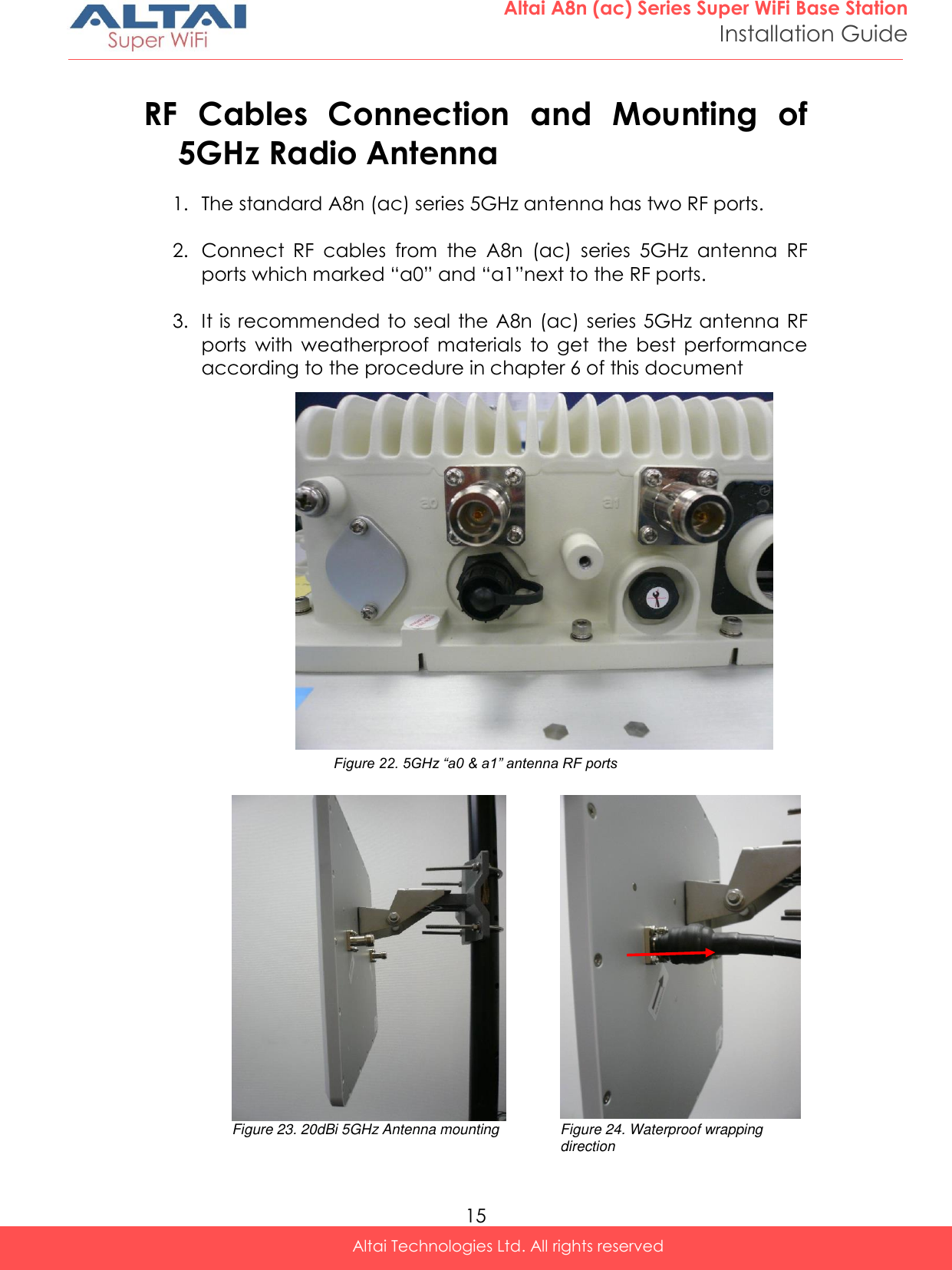
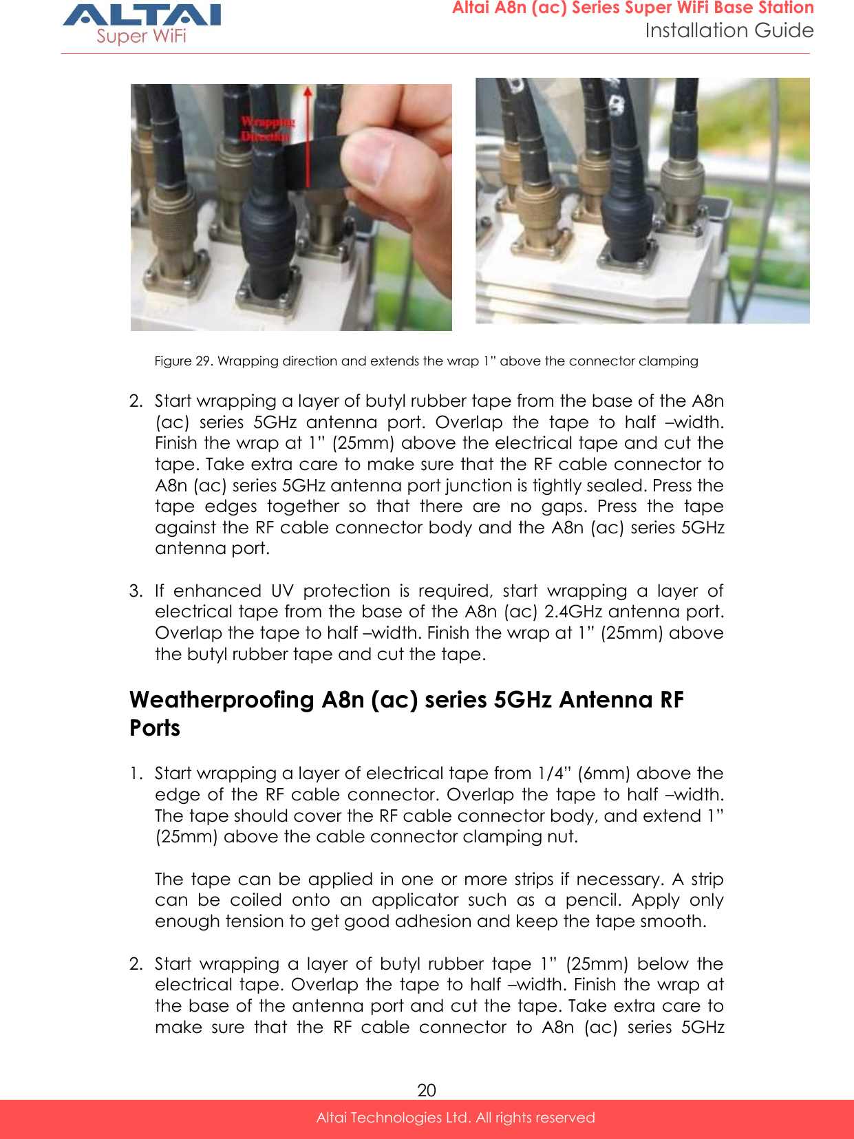
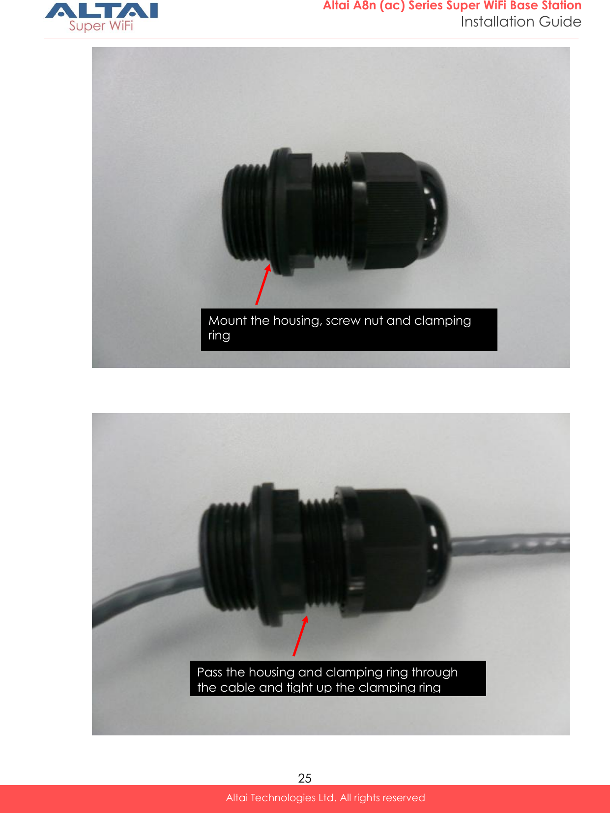
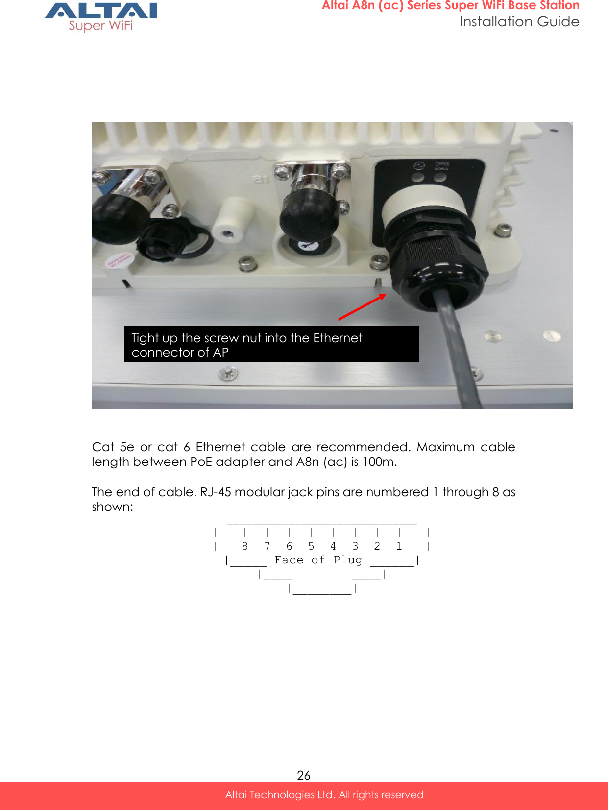
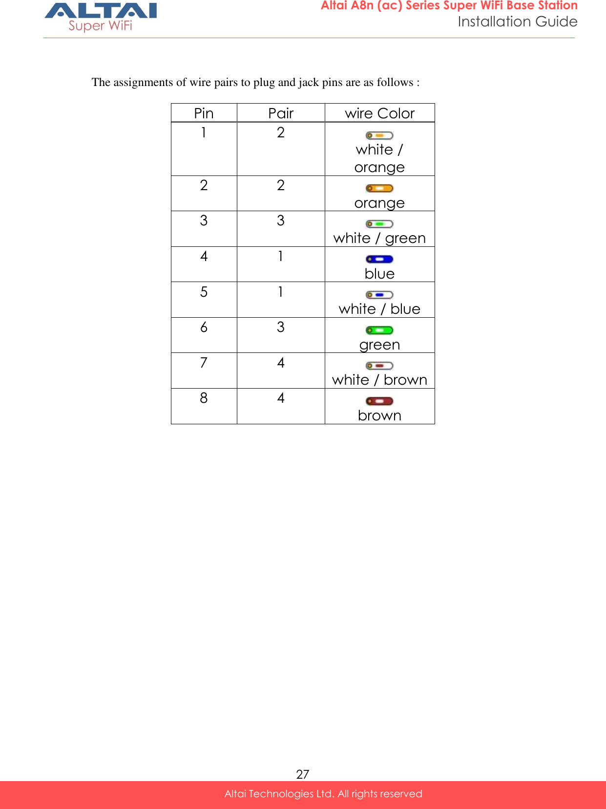
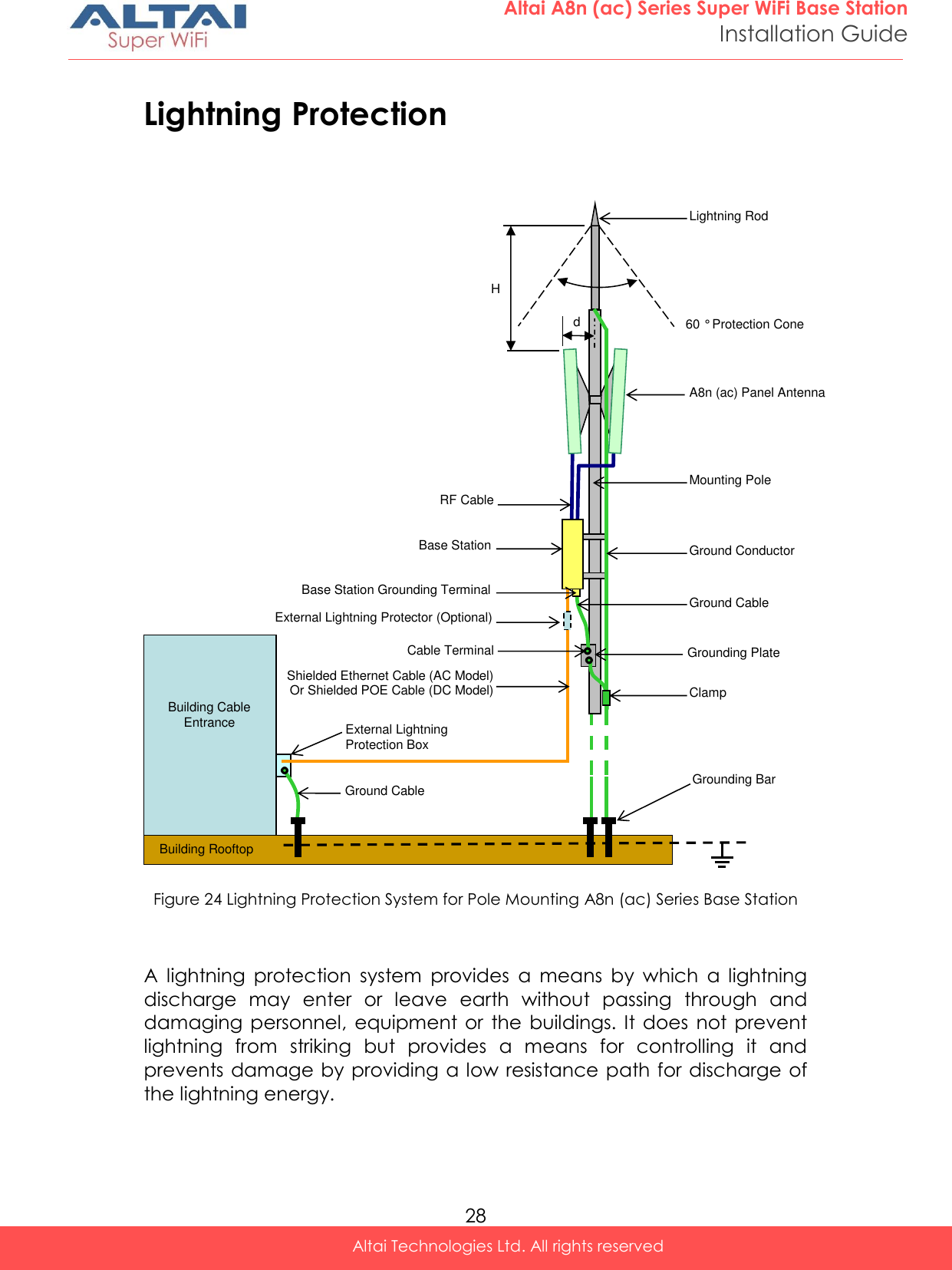
![3 Altai A8n (ac) Series Super WiFi Base Station Installation Guide Altai Technologies Ltd. All rights reserved Figure 2. bottom-view of A8-Ein (ac) Reset back to factory default via reset button Hardware reset button have 2 functions: Soft-reboot [equivalent to UI: Reboot). o Press & Hold the reset button until you see Power LED blink once o Then release it immediately Reset to factory default [equivalent to UI: Reset factory (NOT retain network address)] o Press & Hold the reset button until you see Power LED blink once o Continue pressing the button until you see Power LED blink twice consecutively o Then release it immediately Blink twice Blink once Press&Hold Release here trigger Soft-reboot Release here trigger Reset Factory Time (s) 0s 1s 5s 10s](https://usermanual.wiki/Altai-Technologies/WA8011NAC.Users-Manual-Installation/User-Guide-2853611-Page-8.png)