Altai Technologies WA8011N A8-Ein Super WiFi Base Station User Manual
Altai Technologies Limited A8-Ein Super WiFi Base Station
UserManual.wiki
>
Altai Technologies
>
WA8011N User Manual
User Manual
Navigation menu
Upload a User Manual
Namespaces
Wiki Guide
HTML
PDF
Info
Views
User Manual
Discussion / Help
Navigation
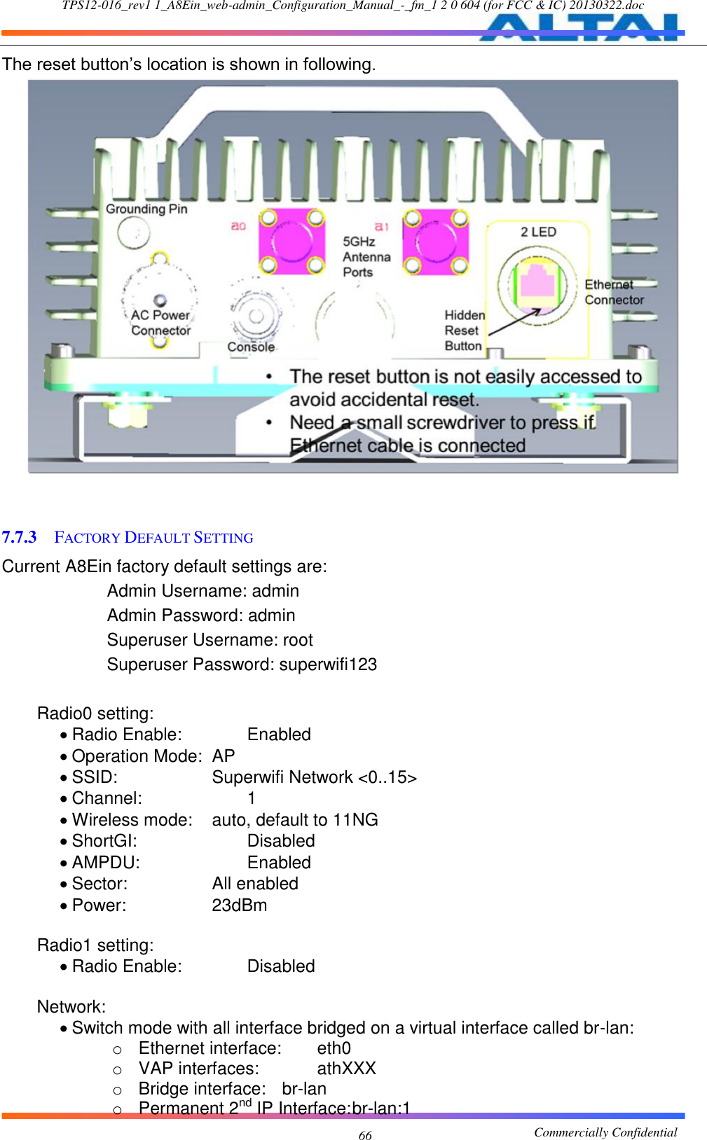
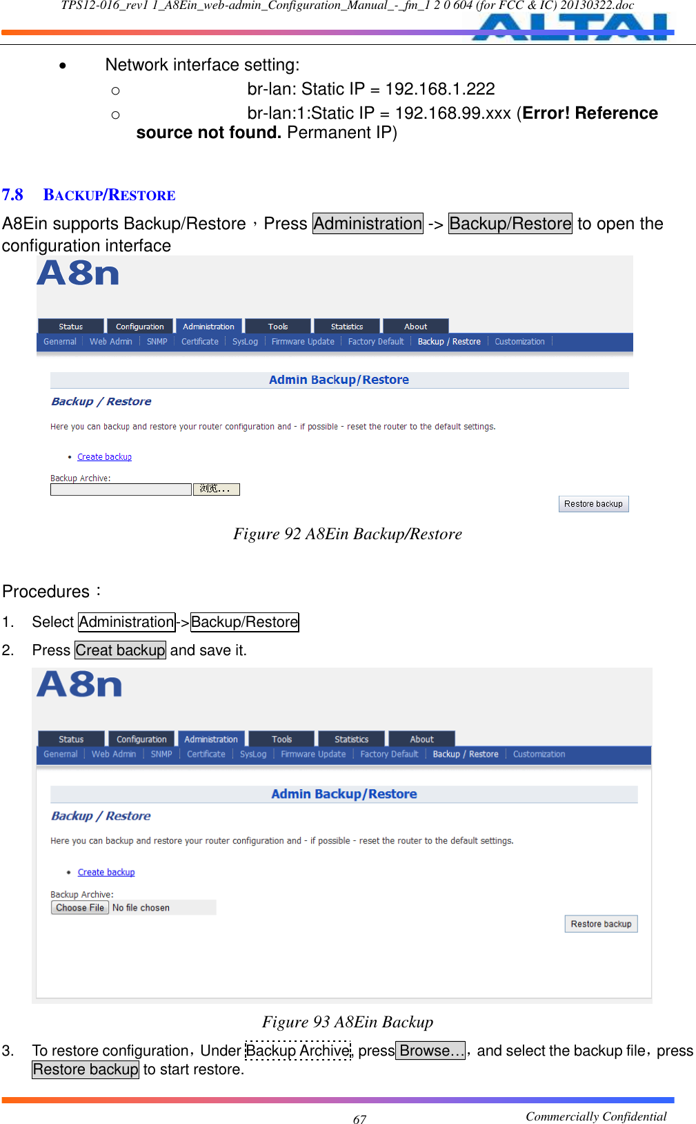
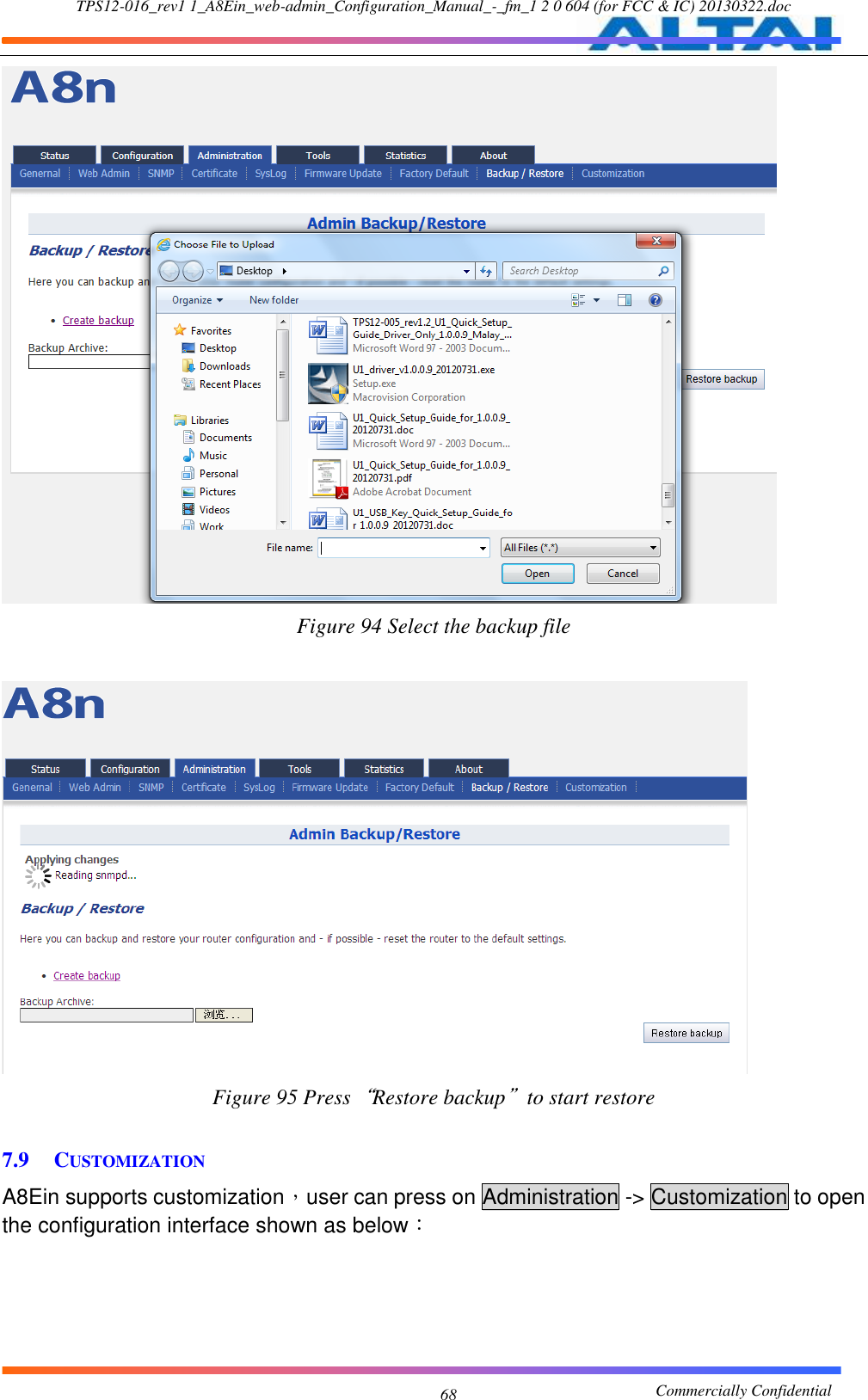
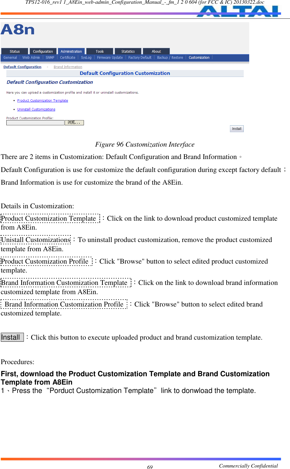
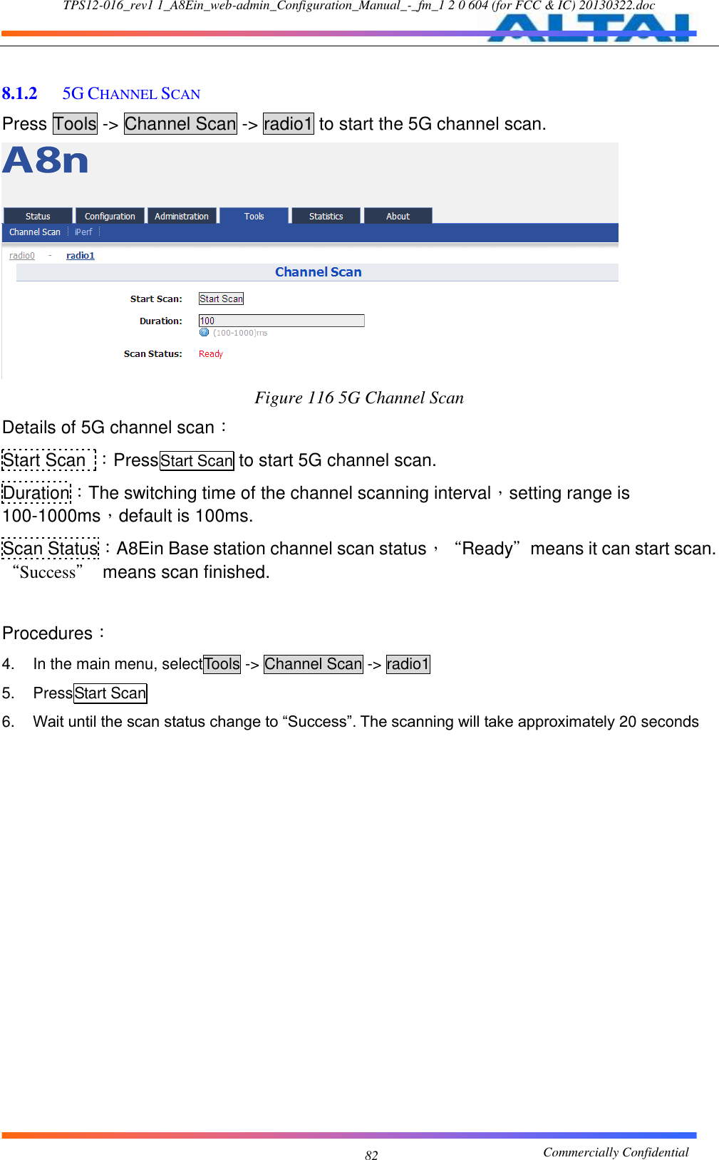
![TPS12-016_rev1 1_A8Ein_web-admin_Configuration_Manual_-_fm_1 2 0 604 (for FCC & IC) 20130322.doc Commercially Confidential 6 Manual Conventions Bold Bold type within paragraph text indicates commands, files names, directory names, paths, output, or returned values. Italic Within commands, italics indicate a variable that the user must specify. Titles of manuals or other published documents are also set in italics. _____ Underline means that you have to pay attention to the words. Courier The courier font indicates output or display. [ ] Within commands, items enclosed in square brackets are optional parameters or values that the user can choose to specify or omit. { } Within commands, item enclosed in braces are options which the user must choose from. | Within commands, the vertical bar separates options. … An ellipsis indicates a repetition of preceding parameter. > The right angle bracket separates successive menu selection. NOTE: This message denotes neutral or positive information that calls out important points to the text. A note provides information that applies only in special cases. Caution: Cautions call special attention to hazards that can cause system damage or data corruption, to a lesser degree than warnings. Warnings: Warnings call special attention to hazards that can cause system damage, data corruption, personal injury, or death.](https://usermanual.wiki/Altai-Technologies/WA8011N/User-Guide-1922229-Page-6.png)
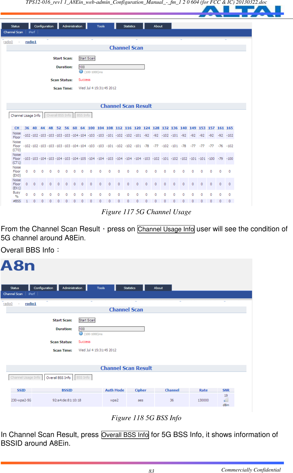
![TPS12-016_rev1 1_A8Ein_web-admin_Configuration_Manual_-_fm_1 2 0 604 (for FCC & IC) 20130322.doc Commercially Confidential 65 Once restore to factory default configuration, user can login to the A8Ein with the following information: A8Ein default IP address:192.168.1.222 Username:root Password:superwifi123 7.7.2 RESET BACK TO FACTORY DEFAULT VIA RESET BUTTON Hardware reset button have 2 functions: Soft-reboot [equivalent to UI: Reboot). o Press & Hold the reset button until you see Power LED blink once o Then release it immediately Reset to factory default [equivalent to UI: Reset factory (NOT retain network address)] o Press & Hold the reset button until you see Power LED blink once o Continue pressing the button until you see Power LED blink twice consecutively o Then release it immediately Time (s) Press&Hold Blink twice Release here trigger Soft-reboot Release here trigger Reset Factory Blink once 0s 1s 5s 10s](https://usermanual.wiki/Altai-Technologies/WA8011N/User-Guide-1922229-Page-65.png)