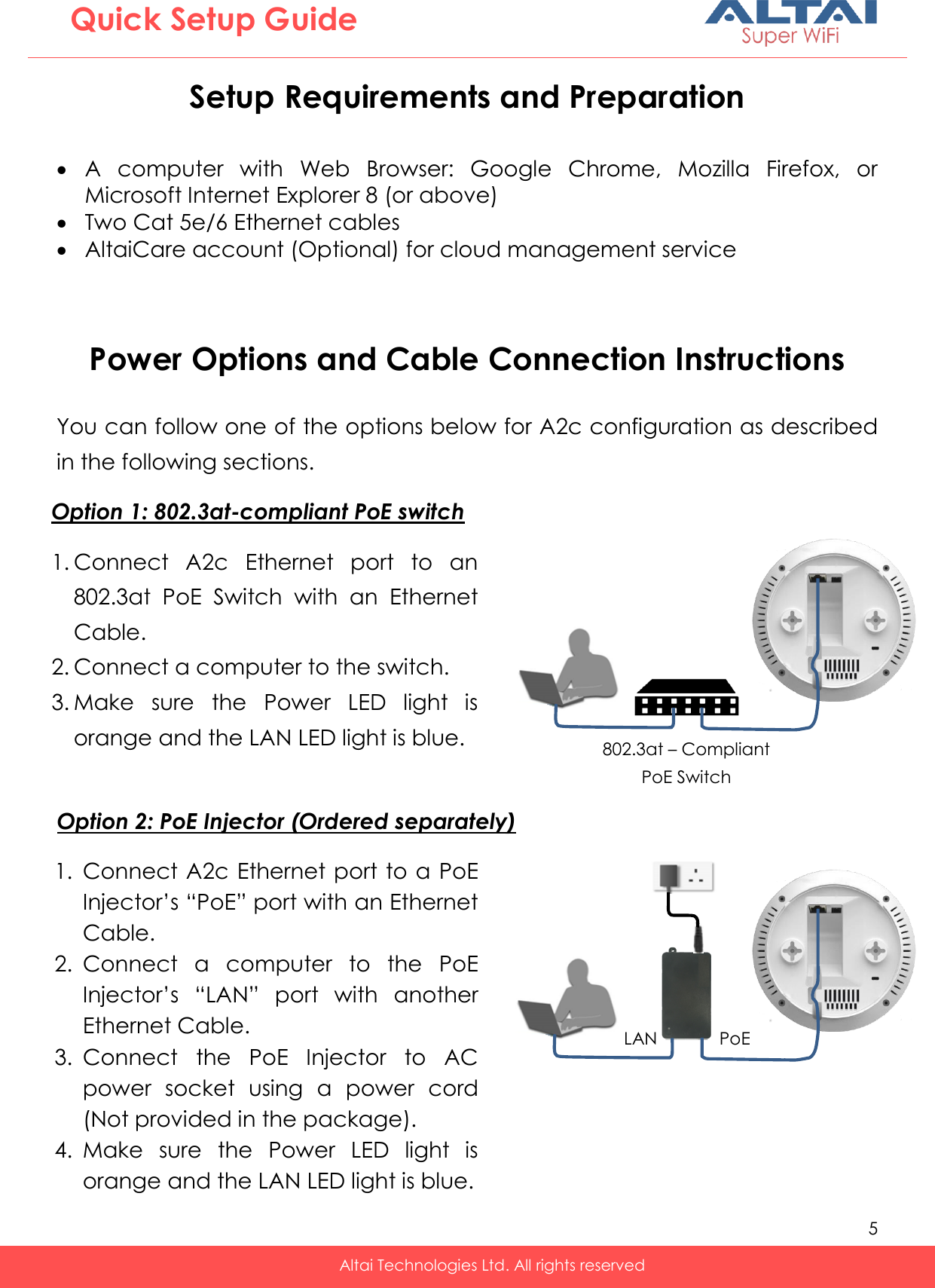
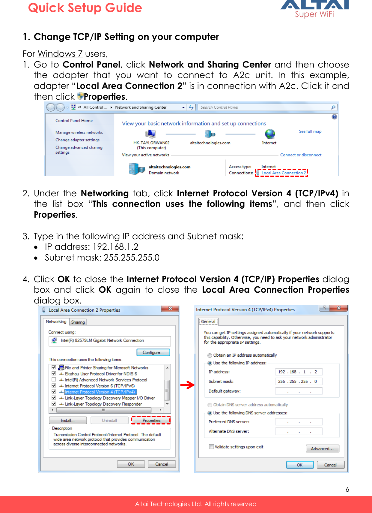
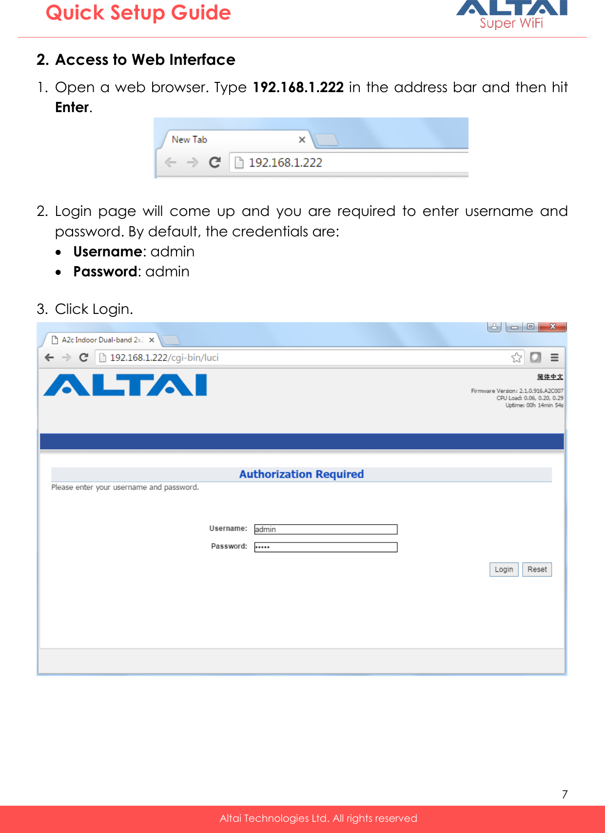
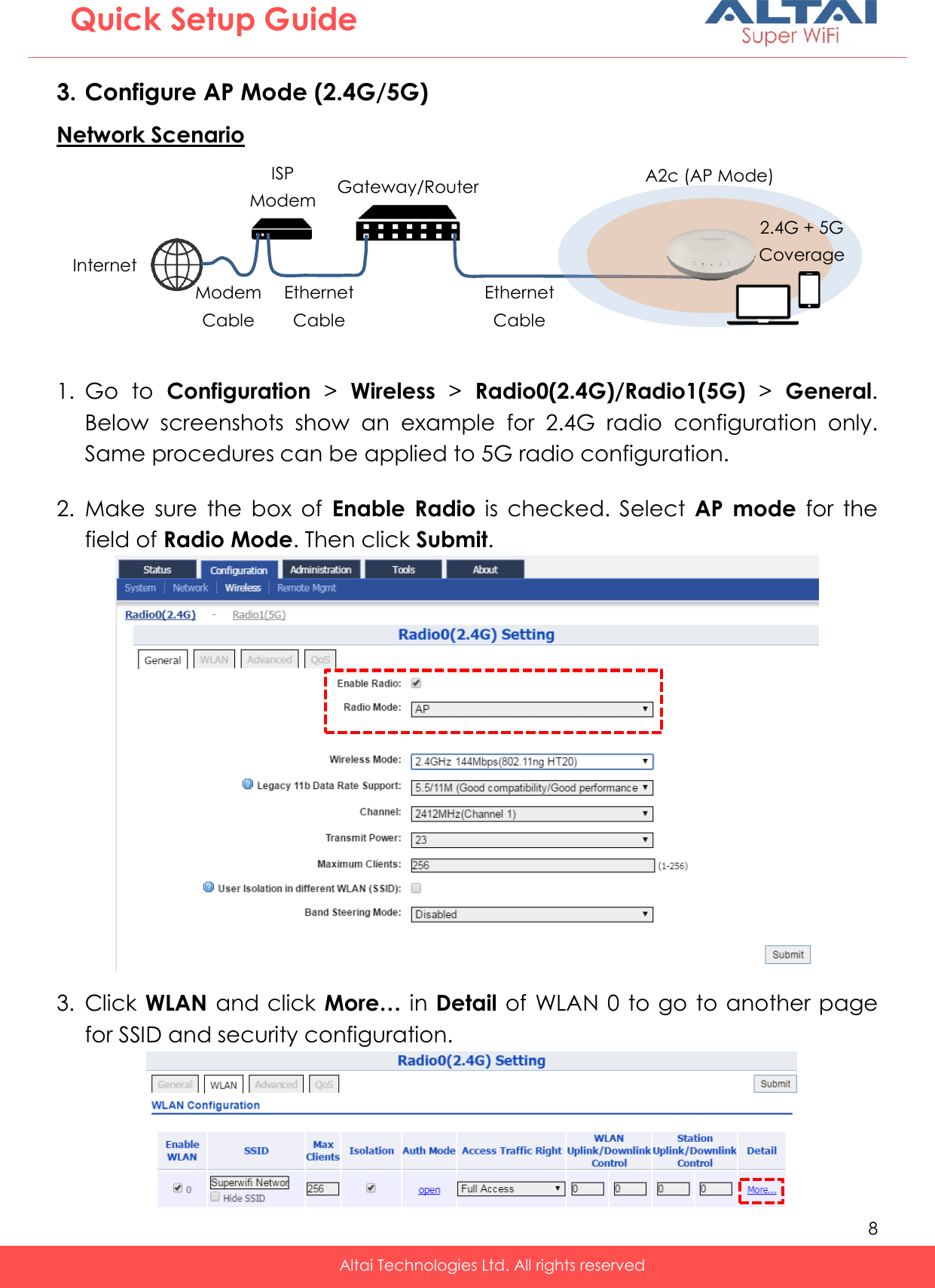
Altai Technologies A22221000 A2c Indoor Dual-Band 2X2 802.11ac AP User Manual A2c Quick Setup Guide

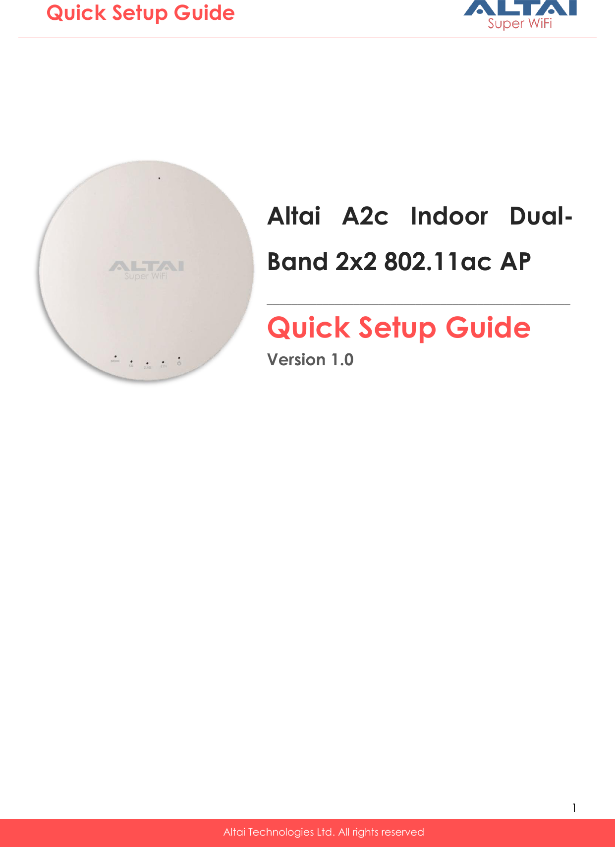
Altai Technologies Limited A2c Indoor Dual-Band 2X2 802.11ac AP A2c Quick Setup Guide

Users Manual_rev

  1   Altai Technologies Ltd. All rights reserved  Quick Setup Guide Altai  A2c  Indoor  Dual-Band 2x2 802.11ac AP  _________________________________________________Quick Setup Guide Version 1.0
  2   Altai Technologies Ltd. All rights reserved  Quick Setup Guide Introduction  Thank  you  for  purchasing  the  Altai  A2c.  This  guide  provides  instructions  to install the product and set it up as AP with minimal effort.       Package Contents  T-Rail Mounting Kit   A2c Main Unit Quick Setup Guide PoE Injector (Optional Item) Ceiling Mounting Kit   15/16in T-Rail Clip    x 2 9/16in T-Rail Clip    x 2 Spacer      x 2 P2.6*10 Screw    x 2 P2.6*25 Screw    x 2  Mounting Bracket    x 1 Mounting Screw    x 2 P3.5*32 Screw    x 2 P2.6*12 Screw    x 2
  3   Altai Technologies Ltd. All rights reserved  Quick Setup Guide Hardware Overview  LED Panel                    Ethernet Ports and Reset Button   0s 2-3s 5-8s Power LED Reboot Factory Reset ETH/PoE IN: It  is  used  to  connect  to  power  source  (see the  Power  Options  in  the  following  section) and  provides  10/100/1000  Mbps  network interface for LAN connection. Reset Button: It serves two functions:  Reboot:  Press  and  hold  the  Reset  Button for 2-3  seconds  until  the  Power  LED  blink once.  Factory  Reset:  Press  and  hold  the  Reset Button for 5-8 seconds until the Power LED blink twice consecutively. Power Solid Orange: Power on Off: No Power  LAN (Ethernet) Solid Blue: LAN Connected Flashing Blue: Data Transmitting/Receiving Off: LAN Disconnected 2.4G/5G Radio WiFi (AP/Repeater/Bridge Mode) Solid Blue (2.4G) / Green (5G): 1. AP Mode on but with no Clients Associated 2. Repeater Mode on but not connected to AP 3. Bridge Mode on but not connected Flashing Blue/Green: Data Transmitting/Receiving Off: Radio Disabled Solid Blue: Remote Management Mode Off: Standalone Mode Operation Mode ETH/PoE IN Reset Button
  4   Altai Technologies Ltd. All rights reserved  Quick Setup Guide P2.6*10 Screw Clip Wall Mounting Screw Mounting Bracket P2.6*12 Screw P3.5*32 Screw Mounting Options  Option 1: Ceiling Mount – Mounting bracket            1. Attach the mounting bracket to the ceiling using  the provided mounting screws and long screws (P3.5*32). 2. Insert  the  provided  short  screws  (P2.6*12)  into  the  bottom  cover  of  A2c. Make  sure  that  the  screws  are  exposed  enough to attach the mounting bracket. 3. Install  the  A2c  on  the  mounting  bracket  by  rotating  the  unit  clockwise about 90 degrees to secure it in place.   Option 2: Ceiling Mount - T-Rail clips           1. Attach the small T-Rail clips to the bottom cover of A2c using the provided short screws (P2.6*10). If extra space is required, use the provided spacers and large T-Rail clips with long screws (P2.6*25). 2. Line  up  the  connected  T-Rail  clips  with  an  appropriately  sized  rail  and press the unit onto the rail until it snaps into place. Lock A2c by revolving P2.6*25 Screw Clip Spacer T-Rail Clips OR
  5   Altai Technologies Ltd. All rights reserved  Quick Setup Guide Setup Requirements and Preparation   A  computer  with  Web  Browser:  Google  Chrome,  Mozilla  Firefox,  or Microsoft Internet Explorer 8 (or above)  Two Cat 5e/6 Ethernet cables  AltaiCare account (Optional) for cloud management service   Power Options and Cable Connection Instructions  You can follow one of the options below for A2c configuration as described in the following sections.              1. Connect A2c Ethernet port to a PoE Injector’s “PoE” port with an Ethernet Cable.  2. Connect  a  computer  to  the  PoE Injector’s  “LAN”  port  with  another Ethernet Cable. 3. Connect  the  PoE  Injector  to  AC power  socket  using  a  power  cord (Not provided in the package). 4. Make  sure  the  Power  LED  light  is orange and the LAN LED light is blue. 1. Connect  A2c  Ethernet  port  to  an 802.3at  PoE  Switch  with  an  Ethernet Cable. 2. Connect a computer to the switch. 3. Make  sure  the  Power  LED  light  is orange and the LAN LED light is blue. Option 2: PoE Injector (Ordered separately) Option 1: 802.3at-compliant PoE switch    PoE LAN 802.3at – Compliant PoE Switch
  6   Altai Technologies Ltd. All rights reserved  Quick Setup Guide 1. Change TCP/IP Setting on your computer For Windows 7 users, 1. Go to  Control Panel, click Network and Sharing Center and then choose the  adapter  that  you  want  to  connect  to  A2c  unit.  In  this  example, adapter “Local Area Connection 2” is in connection with A2c. Click it and then click  Properties.   2. Under  the  Networking  tab,  click  Internet  Protocol  Version  4  (TCP/IPv4)  in the  list  box  “This  connection  uses  the  following  items”,  and  then  click Properties.  3. Type in the following IP address and Subnet mask:  IP address: 192.168.1.2  Subnet mask: 255.255.255.0  4. Click OK to close the Internet Protocol Version 4 (TCP/IP) Properties dialog box  and  click  OK  again  to  close  the  Local  Area  Connection Properties dialog box.
  7   Altai Technologies Ltd. All rights reserved  Quick Setup Guide 2. Access to Web Interface 1. Open a web browser. Type 192.168.1.222 in the address bar and then hit Enter.   2. Login  page  will  come  up  and  you  are  required  to  enter  username  and password. By default, the credentials are:  Username: admin  Password: admin  3. Click Login.
  8   Altai Technologies Ltd. All rights reserved  Quick Setup Guide  3. Configure AP Mode (2.4G/5G) Network Scenario  1. Go  to  Configuration >  Wireless >  Radio0(2.4G)/Radio1(5G) >  General. Below  screenshots  show  an  example  for  2.4G  radio  configuration  only. Same procedures can be applied to 5G radio configuration.  2. Make  sure  the  box  of  Enable  Radio  is  checked.  Select  AP  mode  for  the field of Radio Mode. Then click Submit.   3. Click WLAN and click More… in Detail of WLAN 0 to go to another page for SSID and security configuration.  Internet ISP Modem A2c (AP Mode) Ethernet Cable 2.4G + 5G Coverage Gateway/Router Ethernet Cable Modem Cable
  9   Altai Technologies Ltd. All rights reserved  Quick Setup Guide   4. Make  sure  WLAN  is  enabled  by  checking  the  box.  Type  in  SSID  to  name the wireless network you want to broadcast and then click Submit.  5. Click the tab WLAN Security. Select WPA2-PSK from the drop down menu of  Authentication  Mode  and  select  AES  for  Cipher  Mode.  Type  in  a password  within  8~64  characters  or  numbers  in  Pass  Phrase  and  click Submit.   6. Click Save & Apply at the top right corner to have all changes take effect.   7. Hook  up  the  A2c  as  shown  in  Network Scenario. The SSID should now be broadcast from A2c and can be seen in the computer for wireless connection.
  10   Altai Technologies Ltd. All rights reserved  Quick Setup Guide 4. Configure Gateway Mode (Router Mode) Network Scenario  1. Follow the steps 1 – 6 in Section 3 for the wireless settings.  2. Go to Configuration > Network > General.  3. Select Gateway Mode for Network Setting.  4. Select one of the following ways for Internet Connection Type. If you are not  sure  about  the  connection  options,  consult  your  ISP  for  correct settings.  (a) Static Enter  IP  Address,  Subnet Mask, Default Gateway and DNS  Server  IP  Address  as provided by ISP.    Internet ISP Modem A2c (Gateway/Router Mode) Ethernet Cable 2.4G + 5G Coverage Modem Cable
  11   Altai Technologies Ltd. All rights reserved  Quick Setup Guide (b) DHCP/PPPoE With  these  modes  selected,  IP  Address,  Subnet  Mask  and  Default Gateway  will  be  dynamically  assigned  and  updated  for  each  time  of connection. Two options for DNS Auto Update: - Choose “Enable” to update DNS info along with other IP configuration via DHCP; or - Choose “Disable” for manual input of valid DNS info provided by ISP.  DHCP Configuration: -  -  -  -    For  PPPoE  connection  type,  enter  PPPoE  Username  and  Password provided by ISP for user authentication.  PPPoE Configuration (Minimal): For DNS manual input, select “Disable”   For DNS manual input, select “Disable”
  12   Altai Technologies Ltd. All rights reserved  Quick Setup Guide 5. Click Submit at the page bottom and then click Save & Apply at the top right corner to have all changes take effect.  6. Hook up the A2c as shown in Network Scenario and connect a laptop to the broadcast SSID.  The  laptop will get an IP address  192.168.98.x  with x between 2 and 254 and should be ready for Internet access.  7. To  verify  the  A2c  connection  status,  you  can  access  the  A2c  Web Interface by entering 192.168.98.1 in the browser address bar. Log in to it and Status Overview page (Status > Overview) is shown up.  8. WAN Interface (Ethernet Port, denoted by eth0) should show established status  with  valid  IP  address,  Subnet  Mask,  Default  Gateway  and  DNS Server IP address.          9. LAN  Interface  (2.4G  and  5G  radios,  denoted  by  radio0_x  and  radio1_y respectively  where  x  and  y  are  the  WLAN  ID)  should  show  correct  IP address (192.168.98.1) with DHCP server and NAT enabled.   Static Connection:   DHCP Conection: PPPoE Conection:
  13   Altai Technologies Ltd. All rights reserved  Quick Setup Guide 5. Connect with Cloud-based controller – AltaiCare Network Scenario:  Note: For AltaiCare support, A2c should operate in Switch Mode (Section 3).   1. Users  can  manage  their  A2c  and  set  up  their  hotspot  service  for subscribers with AltaiCare, which is a cloud-based system.  2. Go  to  Configuration >  Network >  General.  Make  sure  A2c  can  reach Internet  and  communicate  with  AltaiCare  by  inputting  valid  IP  settings either via  DHCP or with Static IP configuration. Google Public DNS Server can be considered, e.g. 8.8.8.8 or 8.8.4.4 if you are not sure about the ISP DNS’s Server IP.    A2c_1 (AP) A2c_2 (AP) Local Gateway/Router ISP Modem
  14   Altai Technologies Ltd. All rights reserved  Quick Setup Guide 3. Click Remote Mgmt and check the box of Enable Remote Management. Select AltaiCare as Management Type and Cloud as Connection Type.   4. Select  Full  Management  if  the  device  is  running  in  AP  Mode.  For  Station Mode, Bridge Mode and Repeater Mode, select Monitor Mode instead.  5. Click Submit and then Save & Apply at the top right corner to make all the changes take effect.  6. Follow AltaiCare Quick Start Guide and register the A2c in the system for access management of AP and user service and admission control.  7. A2c will appear as online in AltaiCare AP list if the connection is successful.
  15   Altai Technologies Ltd. All rights reserved  Quick Setup Guide Federal Communication Commission Interference Statement (FCC) – USA This equipment has been tested and found to comply with the limits for a Class B digital device, pursuant to Part  15  of  the  FCC  Rules.  These  limits  are  designed  to  provide  reasonable  protection  against  harmful interference  in  a  residential  installation.  This  equipment  generates,  uses  and  can  radiate  radio  frequency energy and, if not installed and used in accordance with the instructions, may cause harmful interference to  radio  communications.  However,  there  is  no  guarantee  that  interference  will  not  occur  in  a  particular installation. If this equipment does cause harmful interference to radio or television reception, which can be determined by turning the equipment off and on, the user is  encouraged to try to correct the interference by one of the following measures:     Reorient or relocate the receiving antenna.  Increase the separation between the equipment and receiver.  Connect  the  equipment  into  an  outlet  on  a  circuit  different  from  that  to  which  the  receiver  is connected.  Consult the dealer or an experienced radio/TV technician for help.    FCC  Caution:  Any  changes  or  modifications  not  expressly  approved  by  the  party  responsible  for compliance could void the user's authority to operate this equipment.  This device complies with Part 15 of the FCC Rules. Operation is subject to the following two conditions: (1) This device may not cause harmful interference, and (2) this device must accept any interference received, including interference that may cause undesired operation.    This transmitter must not be co-located or operating in conjunction with any other antenna or transmitter. Operations in the 5.15-5.25GHz band are restricted to indoor usage only.    IMPORTANT NOTE: FCC Radiation Exposure Statement: This  equipment  complies  with  FCC radiation  exposure limits  set  forth  for  an uncontrolled  environment.  This equipment  should  be  installed  and  operated  with  minimum  distance  25cm  between  the  radiator  &  your body.  European Conformity (CE) – EU This  is  a  Class B  product.  In  a  domestic  environment, this  product  may cause radio  interference,  in  which case the user may be required to take adequate measures.    Warning A2c may require professional installation depending on the deployment scenario.  Only use the power adaptor supplied with A2c. Using a different power adaptor might damage A2c.   Disclaimer All specifications are subject to change without prior notice.  Altai Technologies assumes no responsibilities for  any  inaccuracies  in  this  document  or  for  any  obligation  to  update  information  in  this  document.  This document is provided for information purposes only. Altai Technologies reserves the right to change, modify, transfer, or otherwise revise this publication without notice.
  16   Altai Technologies Ltd. All rights reserved  Quick Setup Guide                                  Copyright © 2016 Altai Technologies Limited  ALL RIGHTS RESERVED.  Altai Technologies Limited Unit 209, 2/F, Lakeside 2,  10 Science Park West Avenue,  Hong Kong Science Park,  Shatin, New Territories,  Hong Kong  Telephone: +852 3758 6000 Fax: +852 2607 4021 Web: www.altaitechnologies.com  Customer Support Centre:  Email: support@altaitechnologies.com

Navigation menu