Alcatel USA 9928RT LMDS Terminal Station Transceiver User Manual
Alcatel USA Marketing, Inc. LMDS Terminal Station Transceiver
UserManual.wiki
>
Alcatel USA
>
9928RT User Manual
User Manual
Navigation menu
Upload a User Manual
Namespaces
Wiki Guide
HTML
PDF
Info
Views
User Manual
Discussion / Help
Navigation

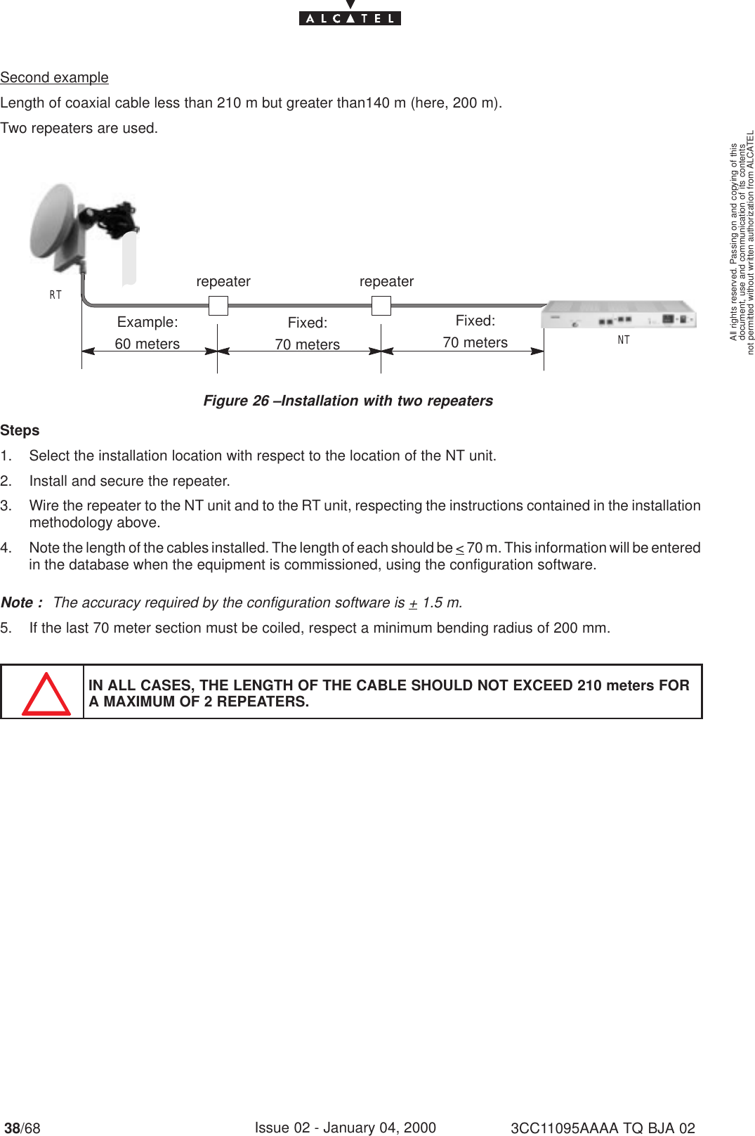
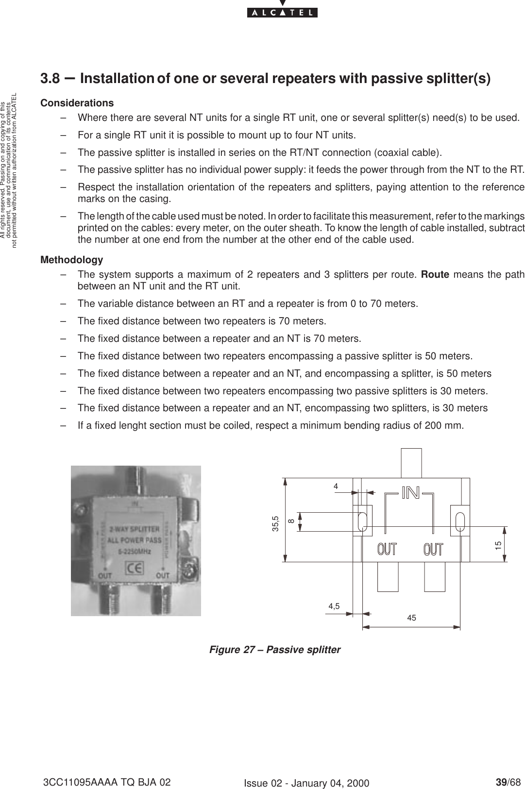
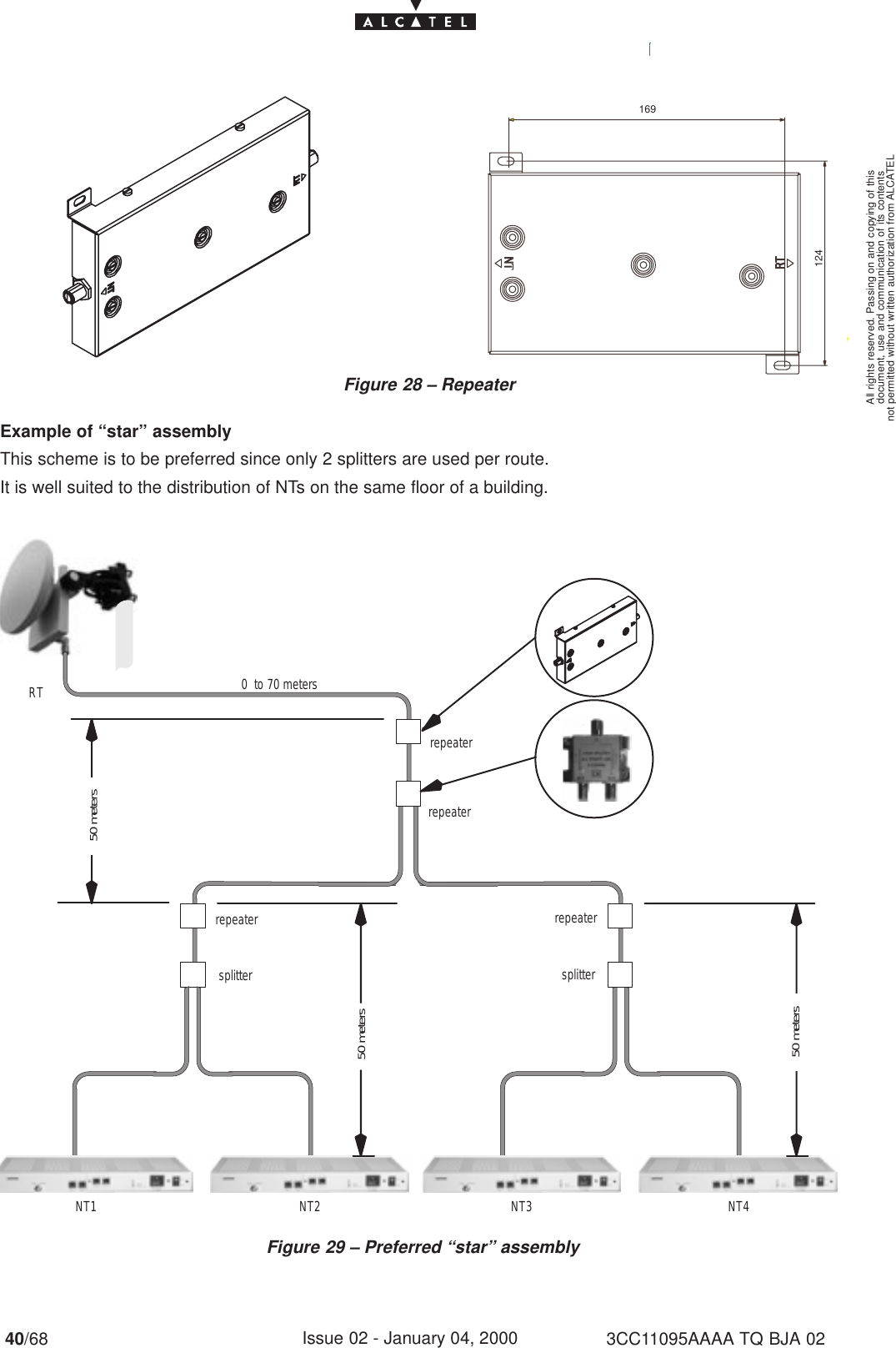
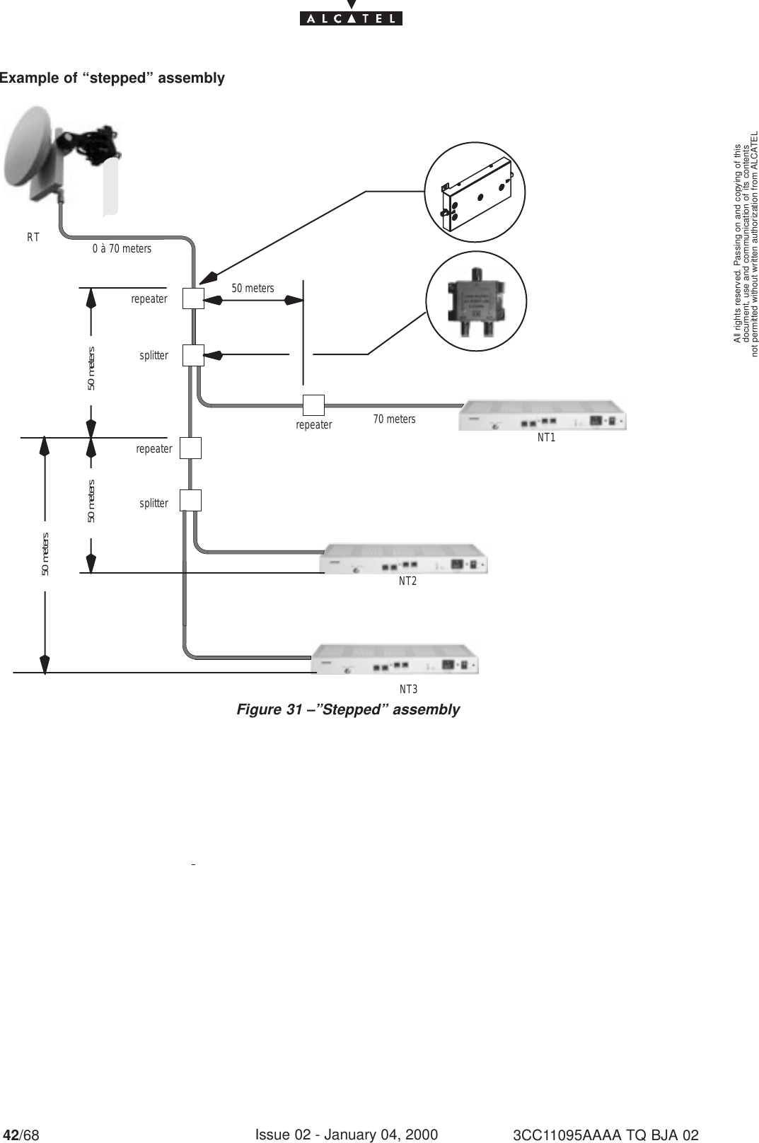
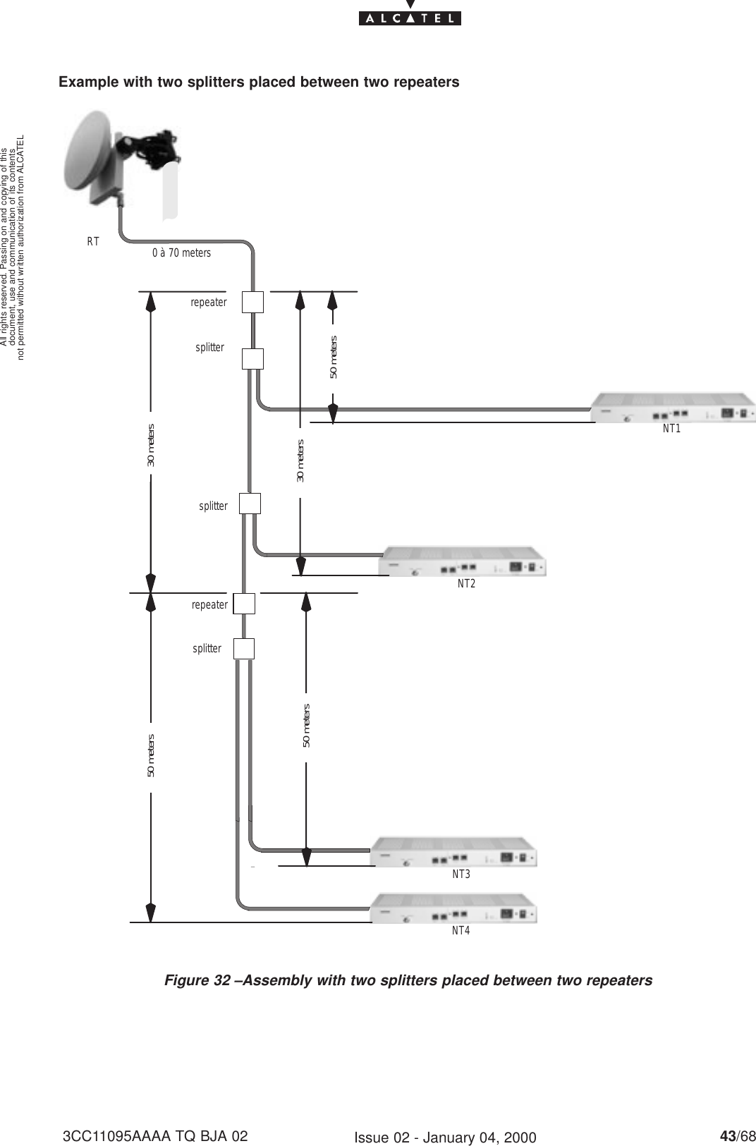
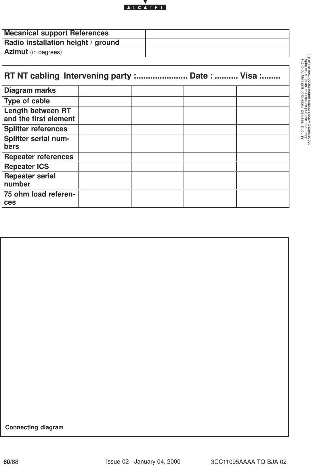
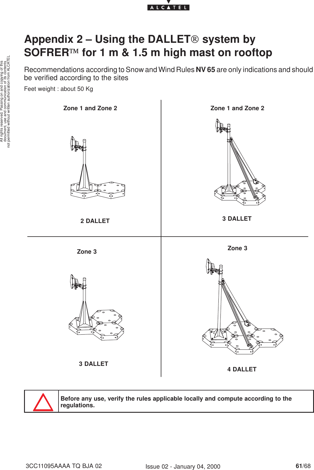
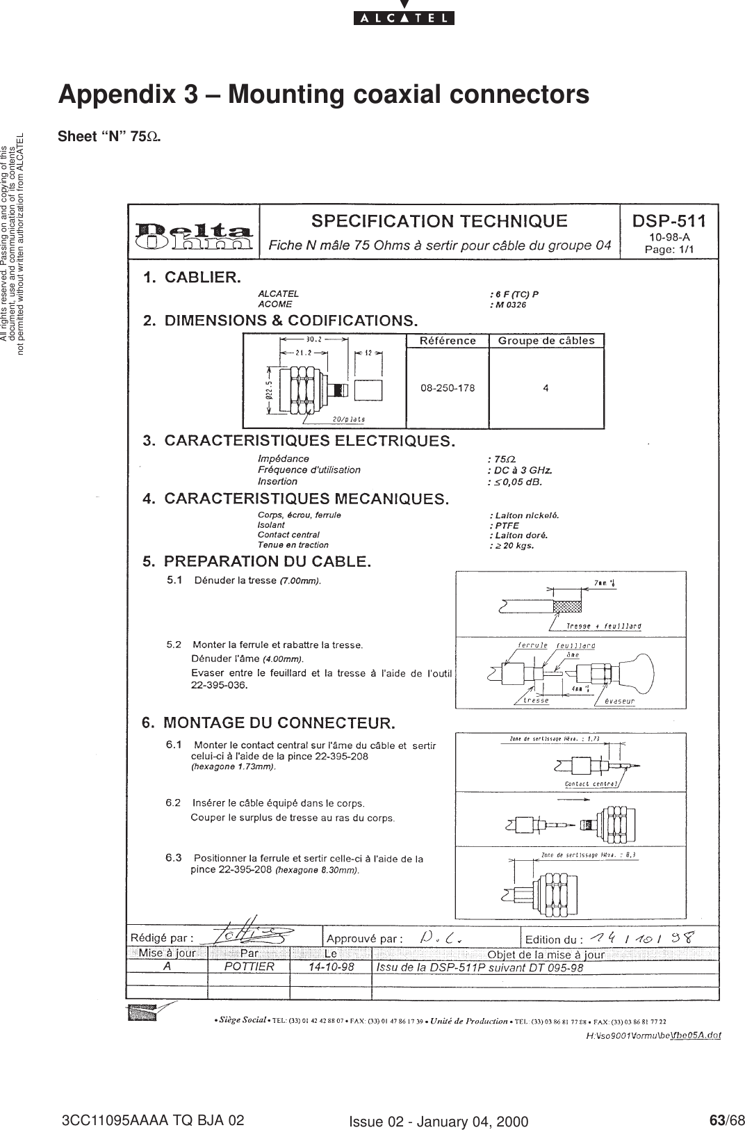
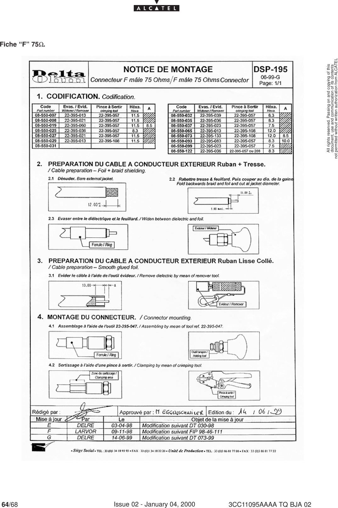
![document, use and communication of its contentsnot permitted without written authorization from ALCATELAll rights reserved. Passing on and copying of this4/68 3CC11095AAAA TQ BJA 02Issue 02 - January 04, 20003.6.3 – Installation of the NT unit on a 19” rack 36. . . . . . . . . . . . . . . . . . . . . . . . . . . . . . . . . . . . 3.6.4 – Grounding the NT unit 36. . . . . . . . . . . . . . . . . . . . . . . . . . . . . . . . . . . . . . . . . . . . . . . . . . 3.7 – Installation of one or more repeater modules 37. . . . . . . . . . . . . . . . . . . . . . . . . . . . . . . . . . . . . . . 3.8 – Installation of one or several repeaters with passive splitter(s) 39. . . . . . . . . . . . . . . . . . . . . . . . 4 – Commissioning the 9900TS Terminal Station 45. . . . . . . . . . . . . . . . . . . . . . . . . . . . . . . . . . . . . . . . 4.1 – Purpose 45. . . . . . . . . . . . . . . . . . . . . . . . . . . . . . . . . . . . . . . . . . . . . . . . . . . . . . . . . . . . . . . . . . . . . . 4.2 – Commissioning the RT unit 45. . . . . . . . . . . . . . . . . . . . . . . . . . . . . . . . . . . . . . . . . . . . . . . . . . . . . . 4.2.1 – Equipment required 45. . . . . . . . . . . . . . . . . . . . . . . . . . . . . . . . . . . . . . . . . . . . . . . . . . . . . 4.2.2 – Site configuration and adjustment procedures 47. . . . . . . . . . . . . . . . . . . . . . . . . . . . . . 4.3 – Commissioning the NT IDU 51. . . . . . . . . . . . . . . . . . . . . . . . . . . . . . . . . . . . . . . . . . . . . . . . . . . . . . 4.4 – Client terminal connections 52. . . . . . . . . . . . . . . . . . . . . . . . . . . . . . . . . . . . . . . . . . . . . . . . . . . . . . 4.4.1 – Ethernet connector 52. . . . . . . . . . . . . . . . . . . . . . . . . . . . . . . . . . . . . . . . . . . . . . . . . . . . . 4.4.2 – G703 connector 52. . . . . . . . . . . . . . . . . . . . . . . . . . . . . . . . . . . . . . . . . . . . . . . . . . . . . . . . 4.4.3 – X21 connector 53. . . . . . . . . . . . . . . . . . . . . . . . . . . . . . . . . . . . . . . . . . . . . . . . . . . . . . . . . 5 – Operation and maintenance 55. . . . . . . . . . . . . . . . . . . . . . . . . . . . . . . . . . . . . . . . . . . . . . . . . . . . . . . . 5.1 – Network supervision 55. . . . . . . . . . . . . . . . . . . . . . . . . . . . . . . . . . . . . . . . . . . . . . . . . . . . . . . . . . . . 5.2 – Preventive maintenance 55. . . . . . . . . . . . . . . . . . . . . . . . . . . . . . . . . . . . . . . . . . . . . . . . . . . . . . . . 5.3 – Corrective maintenance 55. . . . . . . . . . . . . . . . . . . . . . . . . . . . . . . . . . . . . . . . . . . . . . . . . . . . . . . . . 5.3.1 – Methodology 55. . . . . . . . . . . . . . . . . . . . . . . . . . . . . . . . . . . . . . . . . . . . . . . . . . . . . . . . . . . 5.3.2 – Use of 9900LT software programs for alarm localisation 55. . . . . . . . . . . . . . . . . . . . . 5.4 – Changing the NT unit 56. . . . . . . . . . . . . . . . . . . . . . . . . . . . . . . . . . . . . . . . . . . . . . . . . . . . . . . . . . . 5.5 – Changing the RT unit 56. . . . . . . . . . . . . . . . . . . . . . . . . . . . . . . . . . . . . . . . . . . . . . . . . . . . . . . . . . . 6 – Changes of configuration 57. . . . . . . . . . . . . . . . . . . . . . . . . . . . . . . . . . . . . . . . . . . . . . . . . . . . . . . . . . 6.1 – Use of NT unit supervision 57. . . . . . . . . . . . . . . . . . . . . . . . . . . . . . . . . . . . . . . . . . . . . . . . . . . . . . 6.2 – Declaration, deletion, reset of an NT unit 57. . . . . . . . . . . . . . . . . . . . . . . . . . . . . . . . . . . . . . . . . . 6.3 – Implementation of customer services 57. . . . . . . . . . . . . . . . . . . . . . . . . . . . . . . . . . . . . . . . . . . . . 6.4 – Changing an RT unit 58. . . . . . . . . . . . . . . . . . . . . . . . . . . . . . . . . . . . . . . . . . . . . . . . . . . . . . . . . . . . 6.5 – Changing the BS on an NT 58. . . . . . . . . . . . . . . . . . . . . . . . . . . . . . . . . . . . . . . . . . . . . . . . . . . . . . Appendix 1 – 9900 TS INSTALLATION SHEET 59. . . . . . . . . . . . . . . . . . . . . . . . . . . . . . . . . . . . . . . . . . . Appendix 2 – Using the DALLET[ system by SOFRER] for 1 m & 1.5 m high mast on rooftop 61Appendix 3 – Mounting coaxial connectors 63. . . . . . . . . . . . . . . . . . . . . . . . . . . . . . . . . . . . . . . . . . . . . Appendix 4 – List of abbreviations/Liste des abréviations 67. . . . . . . . . . . . . . . . . . . . . . . . . . . . . . . .](https://usermanual.wiki/Alcatel-USA/9928RT/User-Guide-82275-Page-4.png)