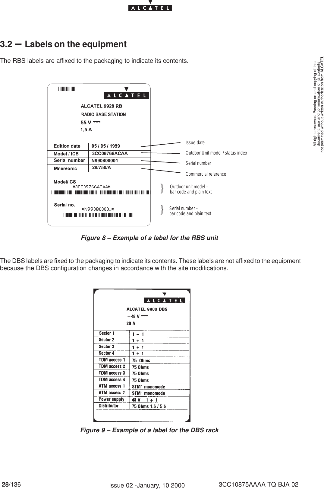
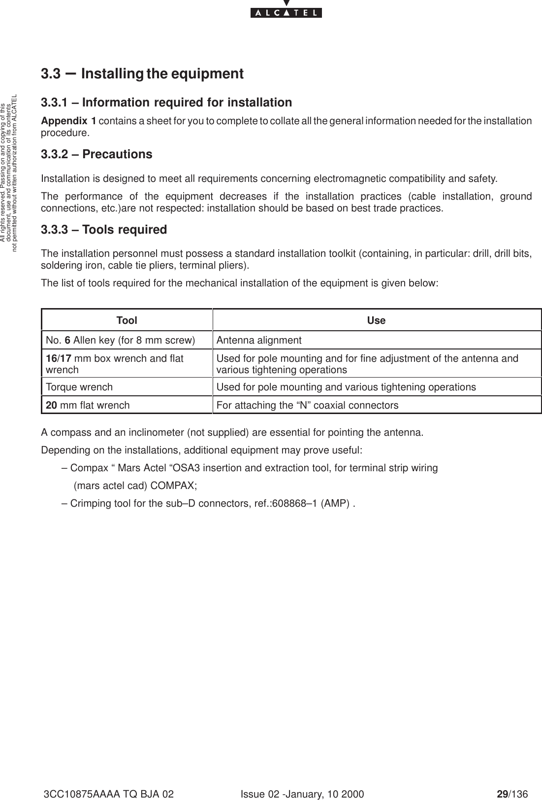
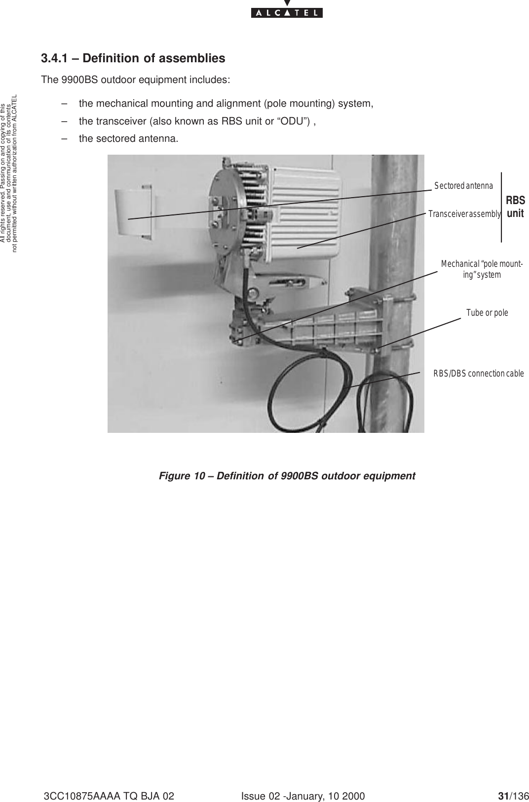
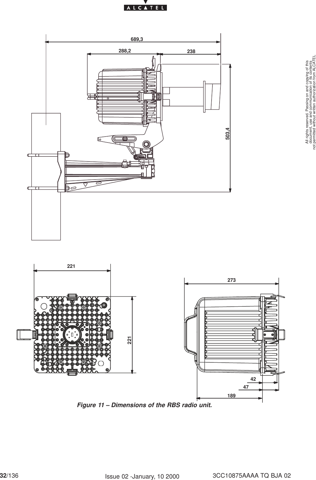
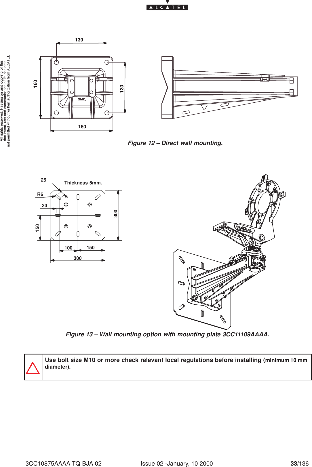
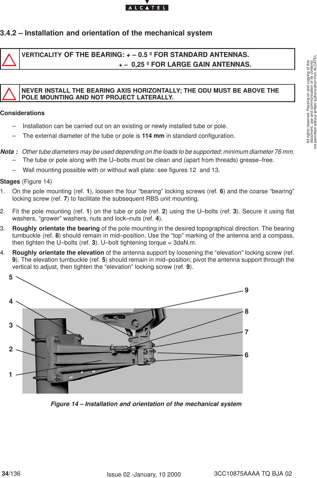
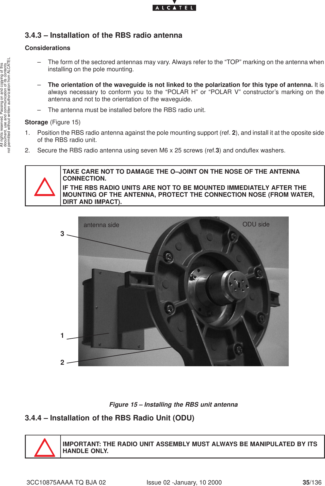
Alcatel USA 9928RB LMDS Base Station Transceiver User Manual
Alcatel USA Marketing, Inc. LMDS Base Station Transceiver
UserManual.wiki
>
Alcatel USA
>
9928RB User Manual
User Manual
Navigation menu
Upload a User Manual
Namespaces
Wiki Guide
HTML
PDF
Info
Views
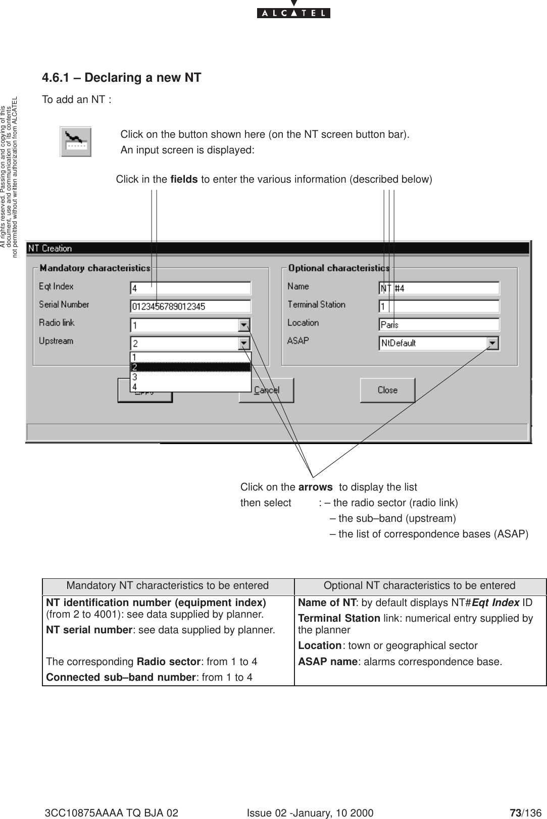
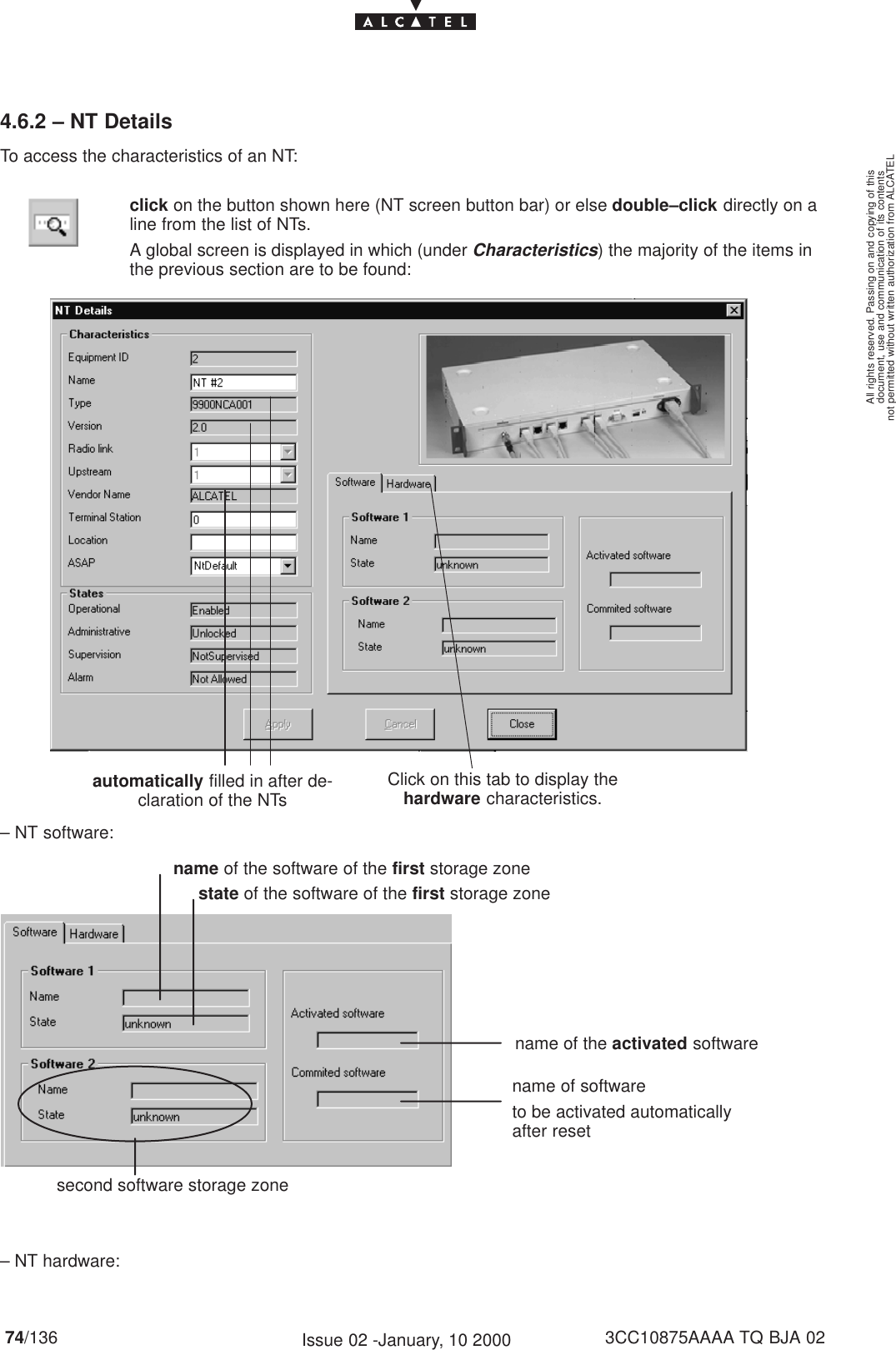
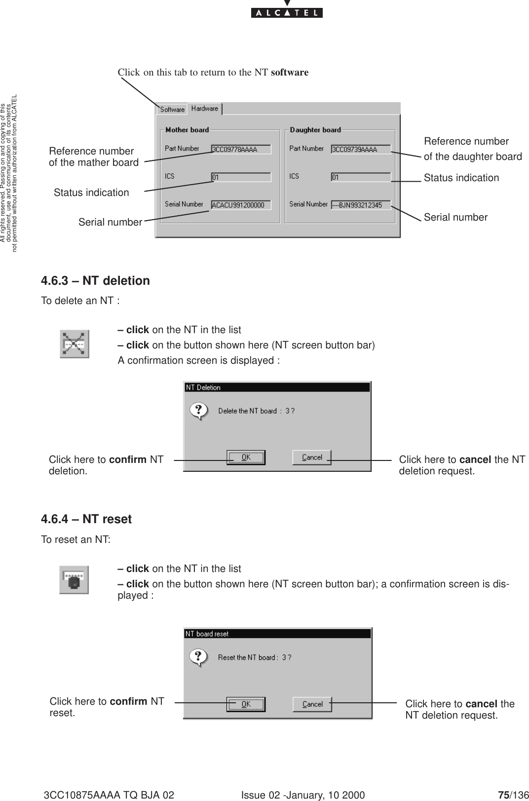
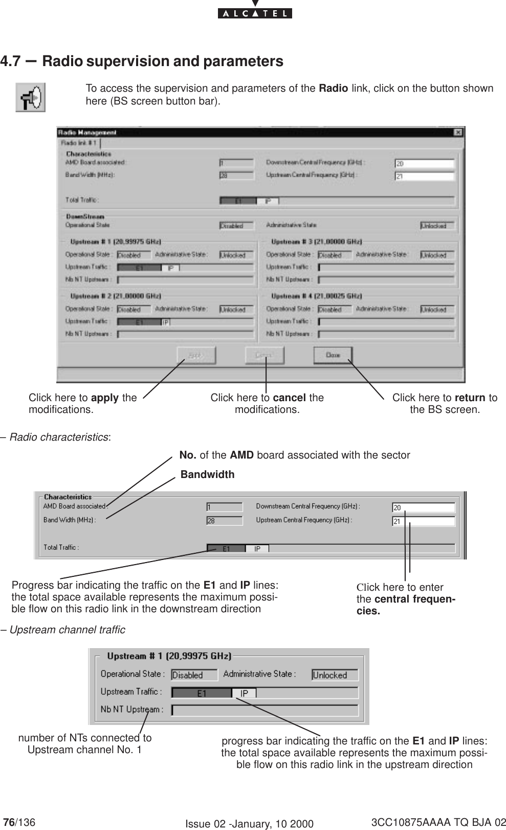
User Manual
Discussion / Help
Navigation