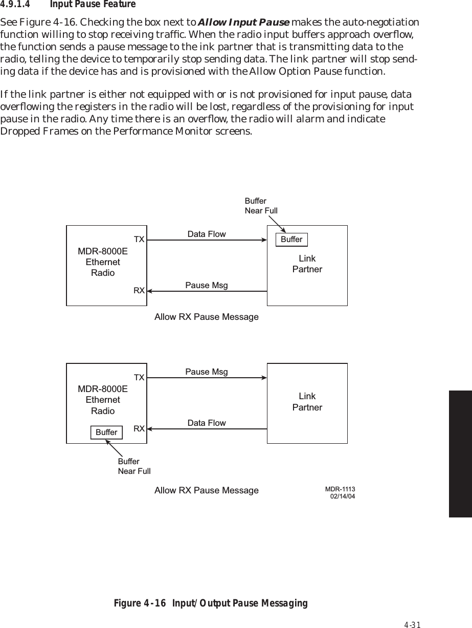
Alcatel USA 8702-50 MDR-8000 User Manual MDR 8000 Radio Family Users Manual Issue 9
Alcatel USA Marketing, Inc. MDR-8000 MDR 8000 Radio Family Users Manual Issue 9
UserManual.wiki
>
Alcatel USA
>
8702-50 User Manual
>
User manual 02
Contents
1.
User manual 01
2.
User manual 02
3.
User manual 03
User manual 02
Navigation menu
Upload a User Manual
Namespaces
Wiki Guide
HTML
PDF
Info
Views
User Manual
Discussion / Help
Navigation


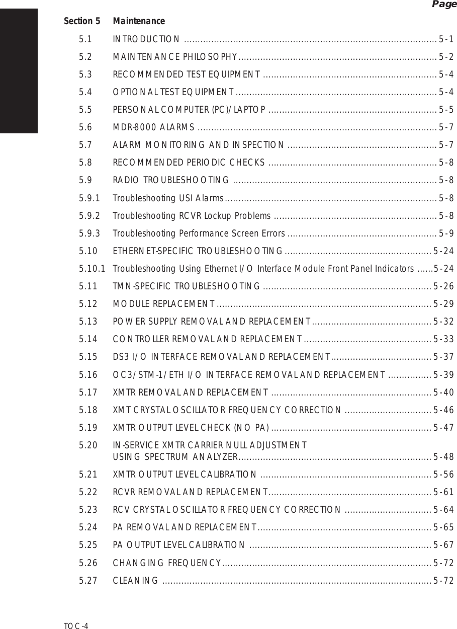
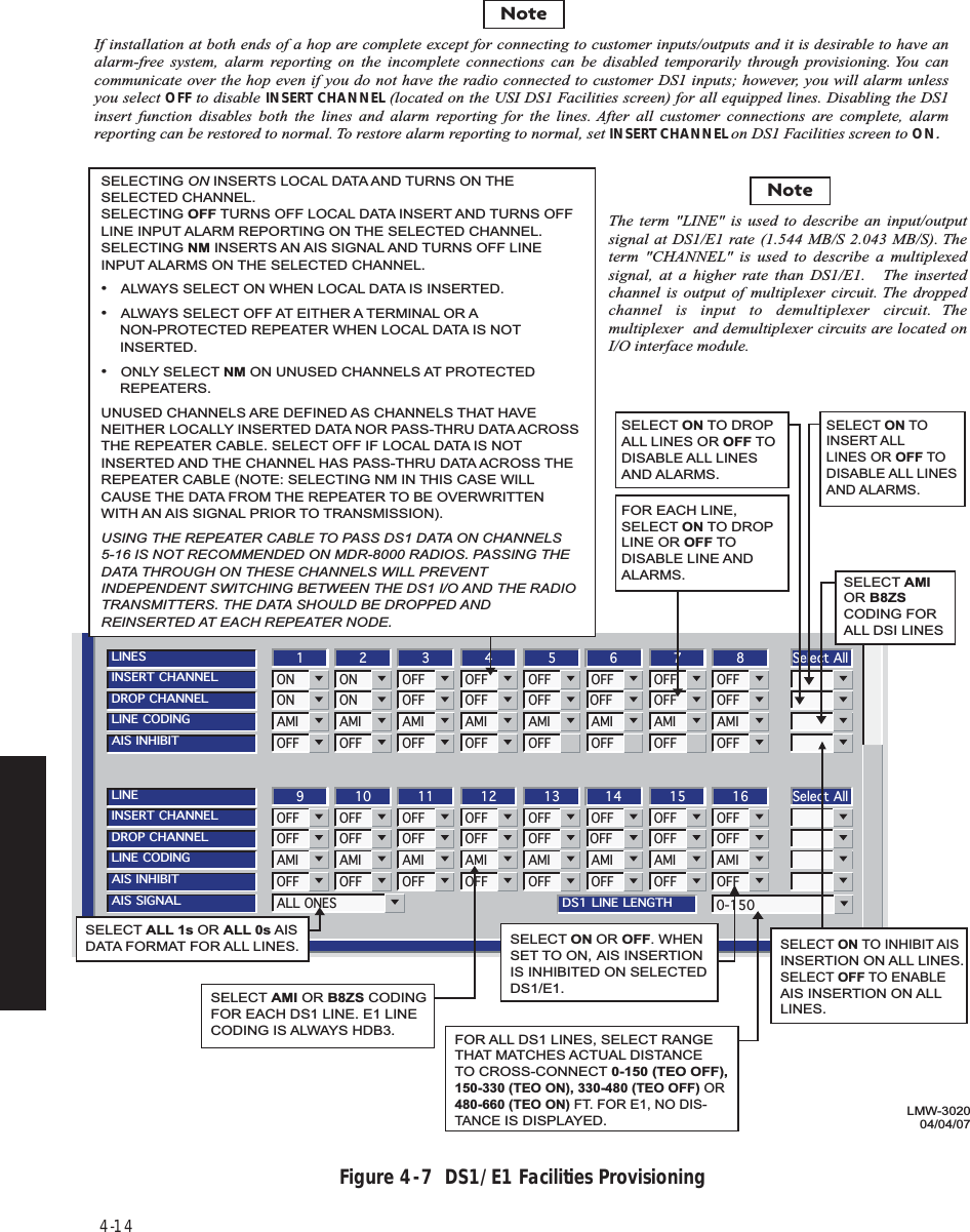
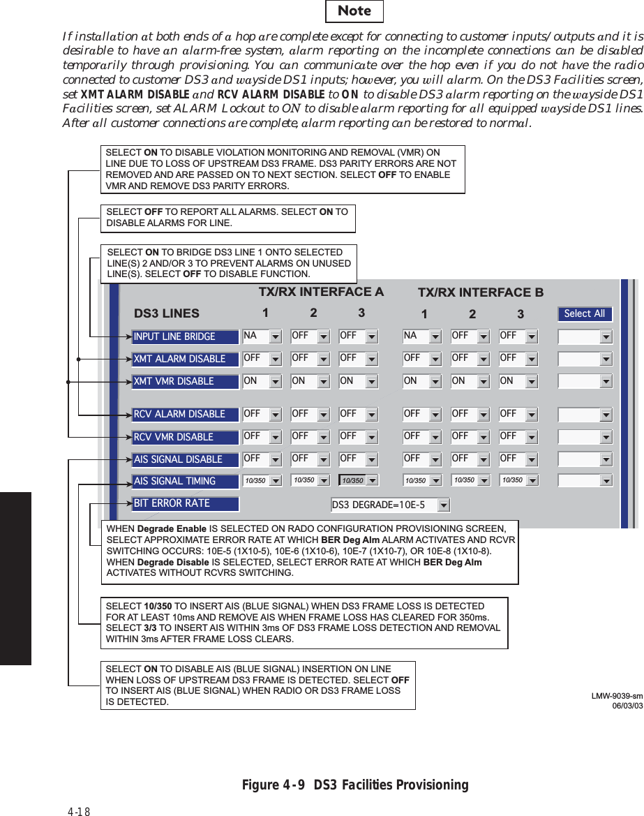
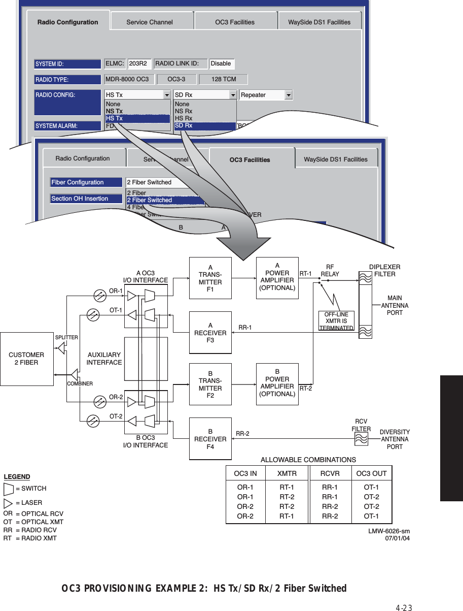
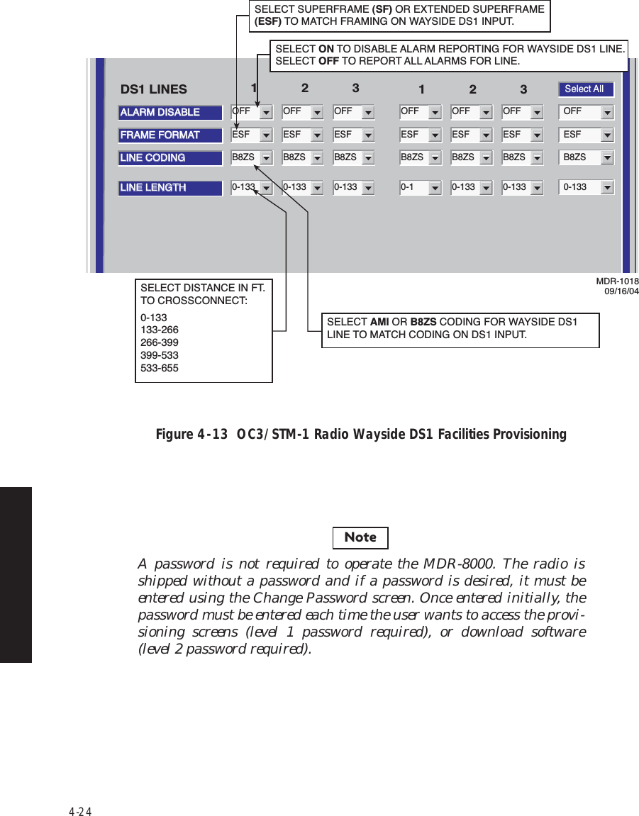
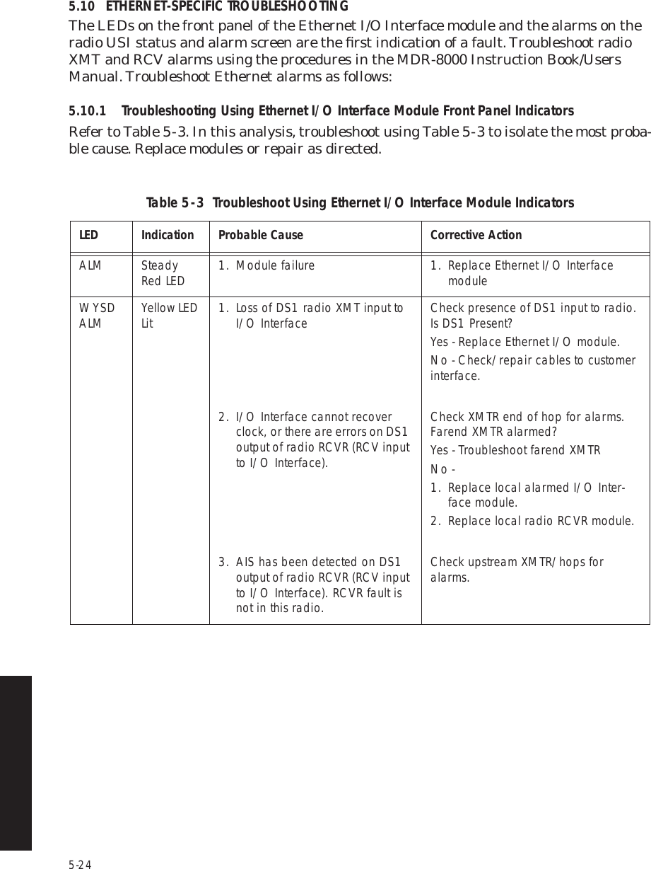
![4-21Figure 4 - 12 OC3/STM-1 Facilities ProvisioningRadio ConfigurationFiber ConfigurationSelect AllSection OH InsertionBER Alarm ThresholdBER Switch Threshold1X10-61X10-64 Fiber SwitchedFrame & B11X10-61X10-61X10-61X10-61X10-61X10-6Alarm DisableOFF OFF OFF OFFService Channel OC3 Facilities WaySide DS1 FacilitiesABTRANSMITTER (IN)ABRECEIVER (OUT)Tuesday, June 3, 2003 5:20:04 AM USI Version R1.04 MDR-8000 OC3 Controller Version R1.4Alcatel User Interface – [Provisioning]File View Setup OptionsF6PerformanceAlarm StatusF4Analog Monitor Station AlarmF7ProvisioningF9User ControlF8F5Prov. SaveF3ELMC Address:ELMC Description:R101OC3 6 GHz TopLOCAL OC3 PROVISIONINGCommunicating***SELECT ERROR RATE (1X10⁻⁵, 1x10⁻⁶, 1x10⁻⁷, OR 1x10⁻⁸) AT WHICH RCVR BER ALARM ACTIVATESOR SELECT DISABLE TO DISABLE ALARM.SELECT OFF, TO ENABLE OC3 ALARMS. SELECTON TO DISABLE ALARMS.SELECT ERROR RATE (1x10⁻⁵, 1x10⁻⁶, 1x10⁻⁷, OR 1x10⁻⁸) WHICH CAUSES OC3 OUTPUT TO BE SWITCHED OR SELECT DISABLE TO DISABLE OC3 OUTPUT SWITCHING.SELECT ERROR RATE (1x10⁻⁵, 1x10⁻⁶, 1x10⁻⁷, OR 1x10⁻⁸) WHICH CAUSES OC3 INPUT TO BE SWITCHED OR SELECT DISABLE TO DISABLE OC3 INPUT SWITCHING.SELECT ERROR RATE (1x10⁻⁵, 1x10⁻⁶, 1x10⁻⁷, OR 1x10⁻⁸) AT WHICH XMTR BER ALARM ACTIVATES OR SELECT DISABLE TO DISABLE ALARM.LMW-4026-sm06/03/03SELECT None TO DISABLE SECTION OVERHEAD (OH) DATA INSERT FUNC-TION IN APPLICATIONS WHERE FRAME AND PARITY INSERT IS PERFORMED EXTERNALLY. SELECT Frame TO INSERT SECTION OVERHEAD DATA. SELECT Frame & B1 TO INSERT SECTION OVERHEAD DATA AND PARITY BIT.NoteIf installation at both ends of a hop are complete except for connecting to customer inputs/outputs and it is desirable to have an alarm-free system, alarm reporting on the incomplete connections can be disabled temporarily through provisioning. You can communicate over the hop even if you do not have the radio connected to customer OC3 and wayside DS1 inputs; however, you will alarm. On the OC3 Facilities screen, set Alarm Disable TRANSMITTER (IN) A and/or B and RECEIVER (OUT) A and/or B to ON to disable OC3 alarm reporting for all equipped wayside DS1 lines. After all customer connections are complete, alarm reporting can be restored to normal.](https://usermanual.wiki/Alcatel-USA/8702-50.User-manual-02/User-Guide-1270259-Page-31.png)
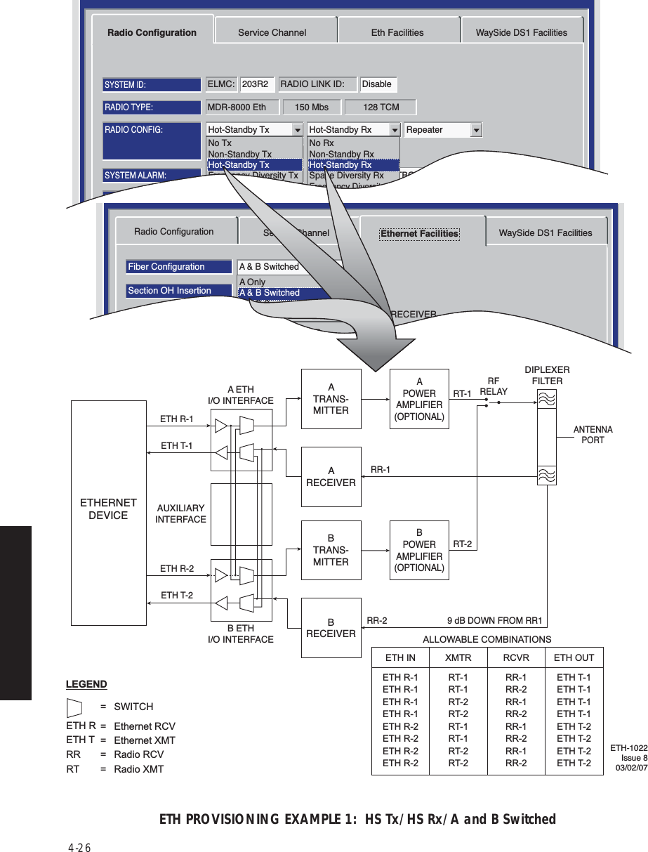
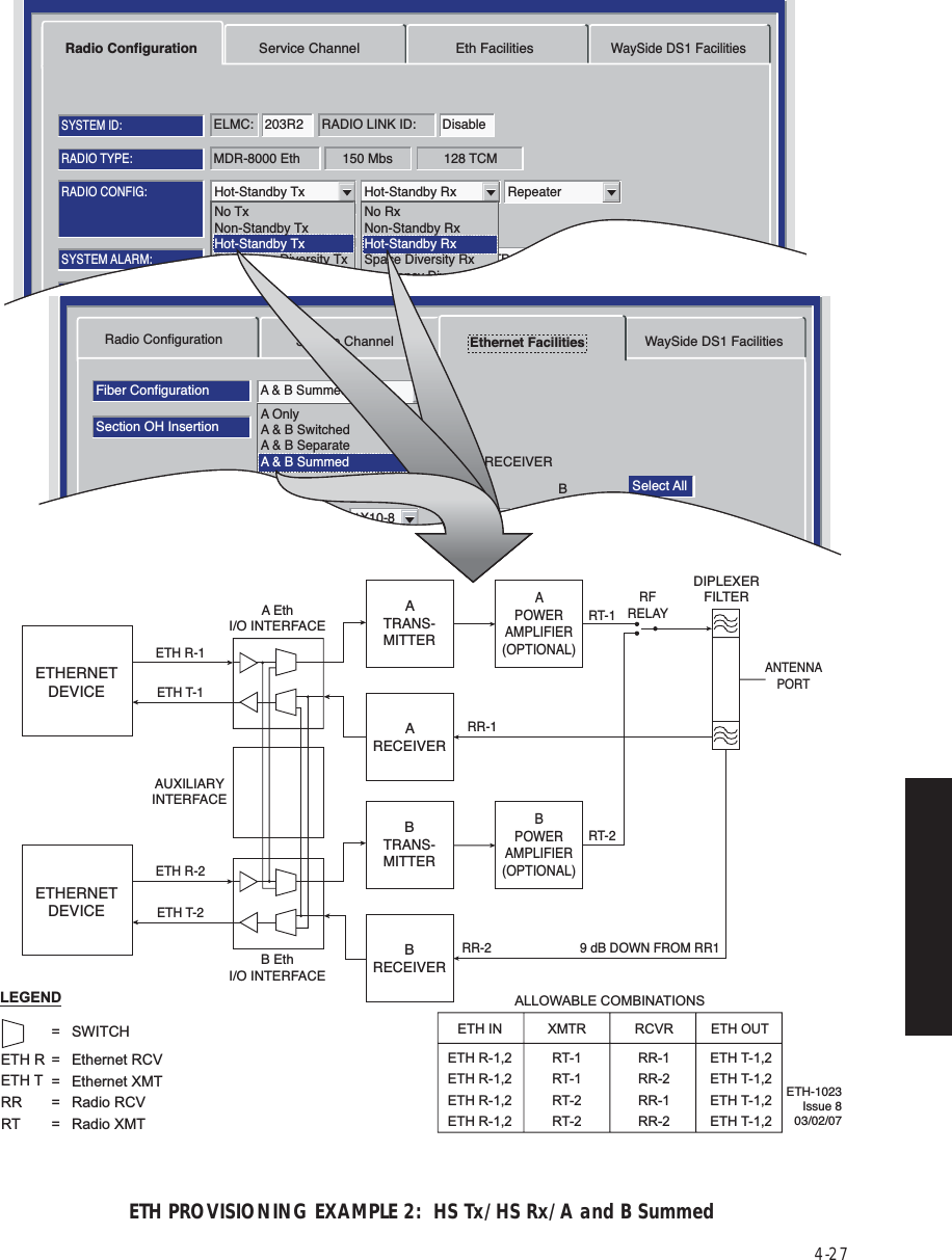
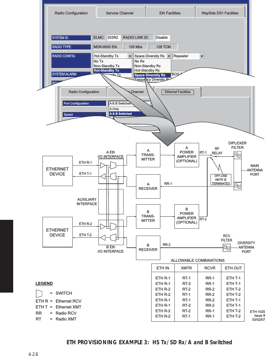
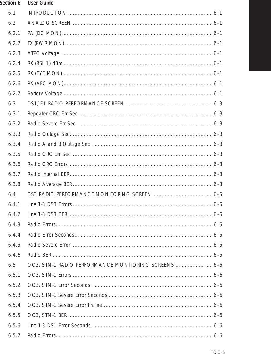
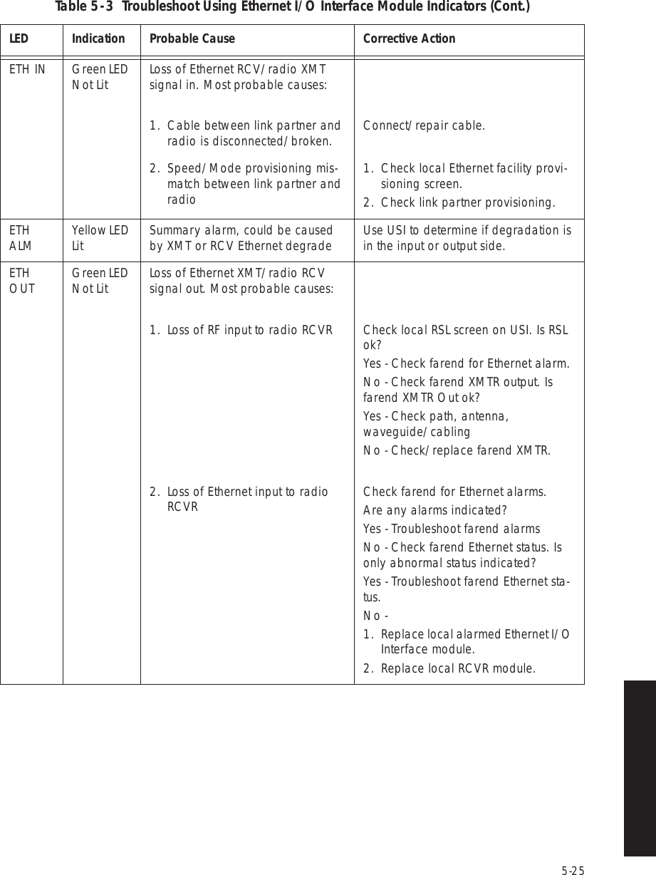
![4-294.9 PROVISION ETHERNET FACILITYSee Figure 4 - 15 to provision the Ethernet radio.Figure 4 - 15 Ethernet Facilities ProvisioningRadio Configuration Service Channel Ethernet FacilitiesLOCAL ETHERNET PROVISIONING (RS-232)Communicating*ELMC Address: 201R2Port Configuration A OnlyPort Operation RegeneratorINPUTDegrade Threshold10 Err/100 SecOUTPUT10 Err/100 SecAuto NegotiateAllow 10 Mb Half DuplexAllow 10 Mb Full DuplexAllow 100 Mb Half DuplexAllow 100 Mb Full DuplexAllow 1000 Mb Full DuplexInput/Output Flow ControlRadio Link Fault PromotionSelect A Only, A & B Switched, A & B Separated, or A & B Summed from dropdown list. See examples 1-34.Monday, November 01, 2004 11:19:08 AMUniversal USI Version R2.00Ethernet Controller Version R2.00Alcatel User Interface – [Universal USI – Provisioning ]File View Setup OptionsF6PerformanceAlarm StatusF4Station AlarmF7 F9ProvisioningUser ControlF8Prov. SaveF3 F5Analog Monitor PasswordF11Select Eth Degrade alarm threshold from drop down list.100 Err/10 Sec10 Err/10 Sec100 Err/100 Sec10 Err/100 Sec25 Err/250 Sec5 Err/250 Sec1 Err/250 Sec When checked (enabled) this feature promotes a link fault to external Ethernet equipment faster than when in the normal operating mode.When checked (enabled) this feature reduces latency and latency variations by allowing frames to be forwarded without waiting for the entire frame to be received. MDR-111402/04/06= Function enabled.All checked (default) shown.All = Ethernet Ports disabled.](https://usermanual.wiki/Alcatel-USA/8702-50.User-manual-02/User-Guide-1270259-Page-39.png)
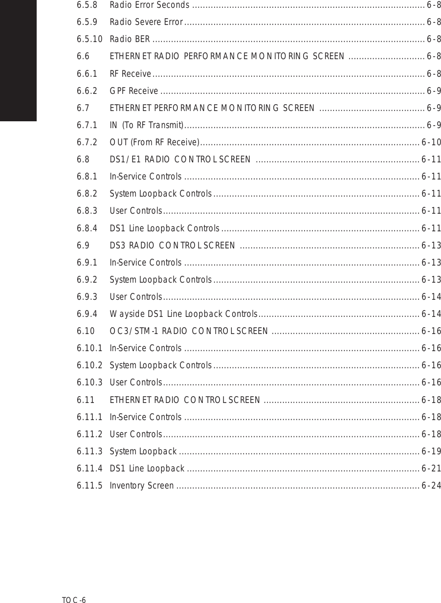
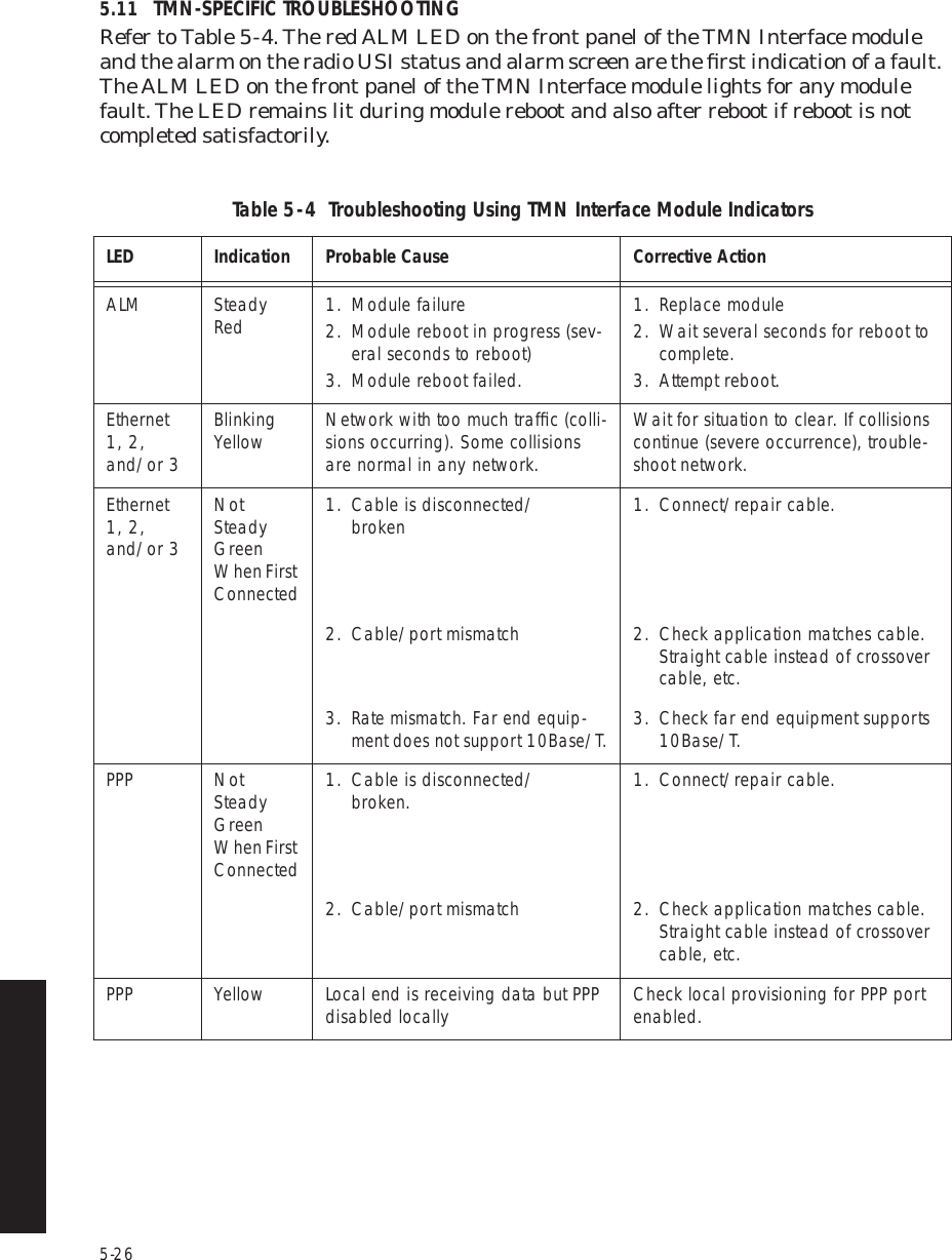
![4-34Figure 4 - 19 Service Channel ProvisioningAUDIO 1AUDIO 2RS-232MCSTMNChannel3MCS TransportRF/RptrPPP TransportRF/RptrChannel E-LeadOff -GNDLevel M-Lead0/0 NormAddressA12AJ308/J309 Input ClocksRSSJ310 Modem J308/J309 TerminationRDS/RAS/RCDChannel 1 Channel 2 Repeater D/1Channel E-Lead All Call Detect1 -GNDDTMFLevel M-Lead 2-Wire Auto Squelch0/0 Norm 00AddressRadio Configuration Service Channel WaySide DS1 FacilitiesDS3 FacilitiesAlcatel User Interface – [System, DS3, and DS1 Provisioning -- MDR-8000 DS3]File View Setup OptionsF6PerformanceAlarm StatusF4Analog Monitor Station AlarmF7ProvisioningF9User ControlF8F5Prov. SaveF3Thursday, March 7, 2000 1:27:15 PM USI Version R1.03 Controller Version R1.03 MDR-8000 3-DS3ELMC Address:ELMC Description:J7914DURANGOLOCAL DS3 PROVISIONINGCommunicating***MDR-103409/16/04](https://usermanual.wiki/Alcatel-USA/8702-50.User-manual-02/User-Guide-1270259-Page-44.png)
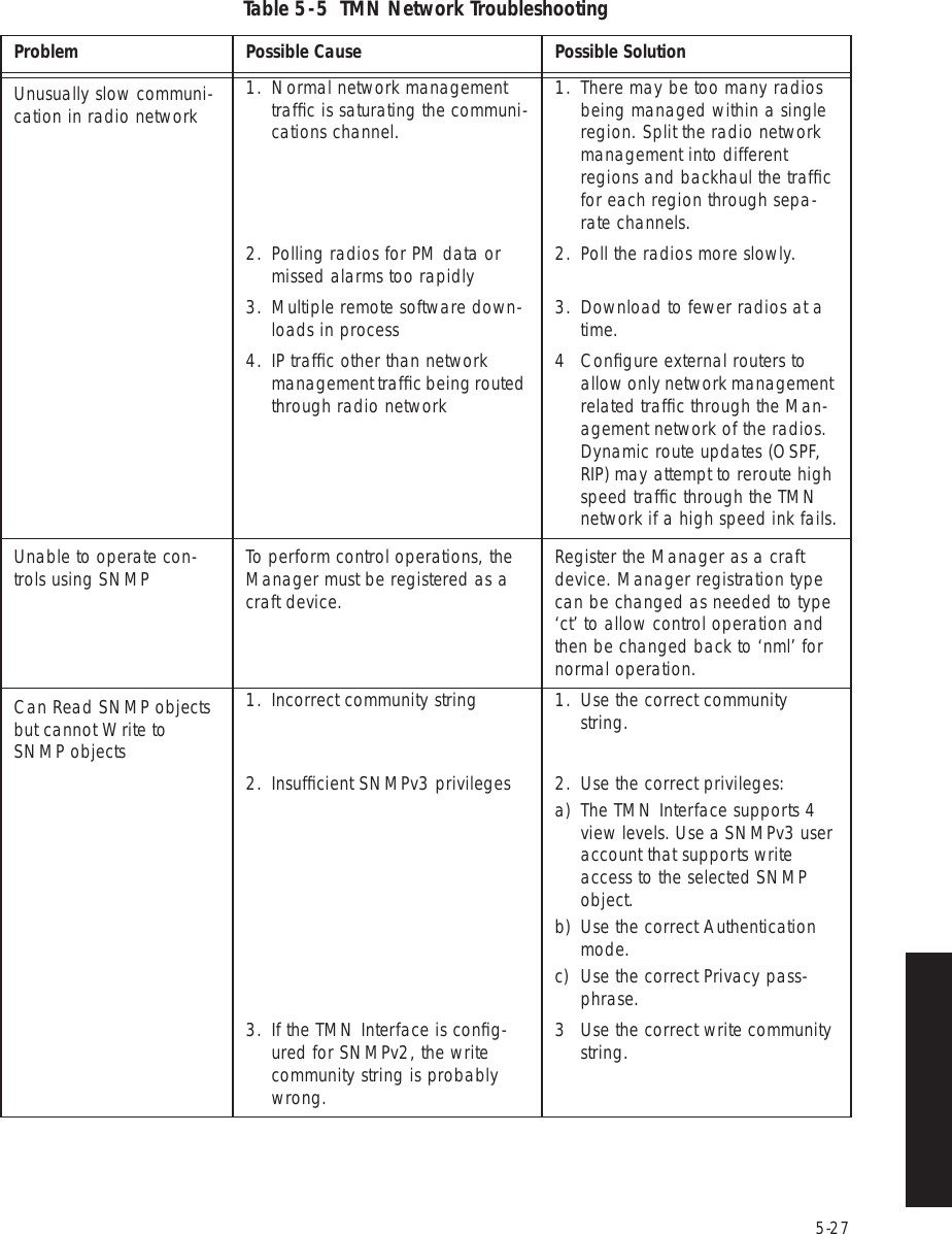
![4-35Figure 4 - 20 Audio 1 Provisioning (Sheet 1 of 2)AUDIO 1:AUDIO 2:RS-232MCSTMNChannel3MCS TransportRF/RptrPPP TransportRF/RptrChannel E-LeadOff -GNDLevel M-Lead0/0 NormAddressA12AJ308/J309 Input ClocksRSSJ310 Modem J308/J309 TerminationRDS/RAS/RCDChannel 1 Channel 2 Repeater D/1Channel E-Lead All Call DetectOff -GNDDTMFLevel M-Lead 2-Wire Auto Squelch0/0 Norm 00AddressRadio Configuration Service Channel WaySide DS1 FacilitiesDS3 FacilitiesAlcatel User Interface – [System, DS3, and DS1 Provisioning -- MDR-8000 DS3]File View Setup OptionsF6PerformanceAlarm StatusF4Analog Monitor Station AlarmF7ProvisioningF9User ControlF8F5Prov. SaveF3Thursday, March 7, 2000 1:27:15 PM USI Version R1.03 Controller Version R1.03 MDR-8000 3-DS3ELMC Address:ELMC Description:J7914DURANGOLOCAL DS3 PROVISIONINGCommunicating***Audio provisioning is required only if 4-wire audio equipment (external equipment not part of the radio) is supplied and the external audio equipment is connected to audio port 1 J316 or audio port 2 J317 on the radio backplane. These provisionable 4-wire audio functions should not be confused with the 2-wire audio handset. The handset is fully operational after it is connected to the TEL jack on the radio controller module, provided the radio is provisioned Audio 1.The most common audio provisioning is: 1:, 2:, or 3: AUDIO 1 0/0 Norm.NoteThe 2-wire handset is transported over Audio 1 only.Note0/0 – RADIO REQUIRES 0 dBm AUDIO INPUT SIGNAL AT CONNECTOR J316. THE RECEIVED AUDIO SIGNALS ARE NOT AMPLIFIED. THE RADIO OUTPUTS 0 dBm ON AUDIO 1 CONNECTOR J316. THIS SELECTION IS NORMALLY SUFFICIENT IF THE RADIO AND EXTERNAL AUDIO EQUIPMENT ARE LOCATED IN THE SAME SHELTER, ROOM AND EVEN BUILDING. LONGER DISTANCES (SUCH AS BETWEEN BUILDINGS) MAY REQUIRE AMPLIFICATION ON THE OUTPUT SIGNAL. IN THIS CASE, SELECT -16/+7 WHERE THE RADIO INPUT REQUIRED IS -16 dBm AND THE RADIO AMPLIFIES RECEIVED AUDIO SIGNALS TO PROVIDE A +7 dBm OUTPUT AT AUDIO 1 CONNECTOR J316. 1:, 2: OR 3: – THE 64 kb/s SERVICE CHANNEL TO BE INSERTED INTO RADIO OVERHEAD IS 1. IF SERVICE CHANNEL 1 IS ALREADY IN USE, SELECT SERVICE CHANNEL 2 (2:) OR SERVICE CHANNEL 3 (3:) FOR THE AUDIO CHANNEL. WHATEVER IS SELECTED FOR SERVICE CHANNEL 1, 2, OR 3, IT MUST BE THE SAME END-TO-END.SELECT E-Lead-24Vdc OR E-Lead GND TO BE APPLIED TO SERVICE CHANNEL E-LEAD.NORM – MODE OF OPERATION SELECTED IS NORMAL. IN THIS MODE THE RADIO REQUIRES AN OFF HOOK SIGNAL FROM THE EXTERNAL AUDIO EQUIPMENT. THIS MEANS THAT THE AUDIO EQUIPMENT USED TO CONNECT TO THE RADIO MUST HAVE E AND M-LEAD SIGNALING CAPABILITY (MOST AUDIO EQUIPMENT DOES HAVE THIS CAPABILITY). IF THE EXTERNAL AUDIO EQUIPMENT DOES NOT HAVE E AND M-LEAD SIGNALING CAPABILITY, SELECT O/H AND A CONSTANT OFF-HOOK SIGNAL WILL BE PROVIDED AUTOMATICALLY BY THE RADIO CONTROLLER SOFTWARE.MDR-1035A09/06/04](https://usermanual.wiki/Alcatel-USA/8702-50.User-manual-02/User-Guide-1270259-Page-45.png)
![4-36Figure 4 - 20 Audio 1 Provisioning (Sheet 2 of 2)AUDIO 1:AUDIO 2:RS-232MCSTMNChannel3MCS TransportRF/RptrPPP TransportRF/RptrChannel E-LeadOff -GNDLevel M-Lead0/0 NormAddressA12AJ308/J309 Input ClocksRSSJ310 Modem J308/J309 TerminationRDS/RAS/RCDChannel 1 Channel 2 Repeater D/1Channel E-Lead All Call DetectOff -GNDDTMFLevel M-Lead 2-Wire Auto Squelch0/0 Norm 00AddressRadio Configuration Service Channel WaySide DS1 FacilitiesDS3 FacilitiesAlcatel User Interface – [System, DS3, and DS1 Provisioning -- MDR-8000 DS3]File View Setup OptionsF6PerformanceAlarm StatusF4Analog Monitor Station AlarmF7ProvisioningF9User ControlF8F5Prov. SaveF3Thursday, March 7, 2000 1:27:15 PM USI Version R1.03 Controller Version R1.03 MDR-8000 3-DS3ELMC Address:ELMC Description:J7914DURANGOLOCAL DS3 PROVISIONINGCommunicating***DOUBLE CLICK TO ENABLE (000 DISPLAYS). ENTER 3-DIGIT STATION CALL NUMBER. OPERATOR CAN DIAL THIS NUMBER AND RING/COMMUNICATE WITH THE STATIONVIA ORDERWIRE. SELECT OFF TO DISABLE DTMF.WHEN All Call Detect IS SELECTED, ALL TELEPHONES RING WHEN CALL IS INITIATED. WHEN All Call Detect IS NOT SELECTED, TELEPHONE ASSOCIATED WITH RADIO WILL NOT RING. USEFUL IN SITUATIONS WHERE MULTIPLE RADIOS ARE CONNECTED AT ONE SITE.MDR-1035B09/16/04DTMF ALLOWS YOU TO DIALUP AND RING OTHER SITES USING THE 2-WIRE HANDSET. ONLY THE RINGING IS DETECTED. COMMUNICATION OVER THE HANDSET IS PARTY-LINE. DTMF ADDRESSING IS A LOCAL FUNCTION NOT A NETWORK FUNCTION, THEREFORE, IF ONE OR MORE RADIOS ARE ASSIGNED THE SAME DTMF ADDRESS, THEY WILL ALL RING WHEN THAT ADDRESS IS DIALED. TO BE ABLE TO USE THE DTMF FUNCTION:1. AUDIO 1 MUST BE SELECTED FOR 2-WIRE HANDSET OPERATION.2. DTMF MUST BE TURNED ON (CHECKED) ON THE AUDIO PROVISIONING SCREEN.3. 2-WIRE HANDSET MUST BE CONNECTED TO TEL JACK ON CONTROLLER MODULE.4. RADIOS MUST BE PROVISIONED WITH DTMF ADDRESS.](https://usermanual.wiki/Alcatel-USA/8702-50.User-manual-02/User-Guide-1270259-Page-46.png)
![4-37Figure 4 - 21 Audio 2 ProvisioningAUDIO 1:AUDIO 2:RS-232MCSTMNChannel3MCS TransportRF/RptrPPP TransportRF/RptrChannel E-LeadOff -GNDLevel M-Lead0/0 NormAddressA12AJ308/J309 Input ClocksRSSJ310 Modem J308/J309 TerminationRDS/RAS/RCDChannel 1 Channel 2 Repeater D/1Channel E-Lead All Call DetectOff -GNDDTMFLevel M-Lead 2-Wire Auto Squelch0/0 Norm 00AddressRadio Configuration Service Channel WaySide DS1 FacilitiesDS3 FacilitiesAlcatel User Interface – [System, DS3, and DS1 Provisioning -- MDR-8000 DS3]File View Setup OptionsF6PerformanceAlarm StatusF4Analog Monitor Station AlarmF7ProvisioningF9User ControlF8F5Prov. SaveF3Thursday, March 7, 2000 1:27:15 PM USI Version R1.03 Controller Version R1.03 MDR-8000 3-DS3ELMC Address:ELMC Description:J7914DURANGOLOCAL DS3 PROVISIONINGCommunicating***MDR-1036A09/06/040/0 – RADIO REQUIRES 0 dBm AUDIO INPUT SIGNAL AT CONNECTOR J317. THE RECEIVED AUDIO SIGNALS ARE NOT AMPLIFIED. THE RADIO OUTPUTS 0 dBm ON AUDIO 2 CONNECTOR J317. THIS SELECTION IS NORMALLY SUFFICIENT IF THE RADIO AND EXTERNAL AUDIO EQUIPMENT ARE LOCATED IN THE SAME SHELTER, ROOM AND EVEN BUILDING. LONGER DISTANCES (SUCH AS BETWEEN BUILDINGS) MAY REQUIRE AMPLIFICATION ON THE OUTPUT SIGNAL. IN THIS CASE, SELECT -16/+7 WHERE THE RADIO INPUT REQUIRED IS -16 dBm AND THE RADIO AMPLIFIES RECEIVED AUDIO SIGNALS TO PROVIDE A +7 dBm OUTPUT AT AUDIO 2 CONNECTOR J317. 1:, 2: OR 3: – THE 64 kb/s SERVICE CHANNEL TO BE INSERTED INTO RADIO OVERHEAD IS 1, 2, or 3. IF SERVICE CHANNEL 1 IS ALREADY IN USE, SELECT SERVICE CHANNEL 2 (2:) OR SERVICE CHANNEL 3 (3:) FOR THE AUDIO CHANNEL. WHATEVER IS SELECTED FOR SERVICE CHANNEL 1, 2, OR 3, IT MUST BE THE SAME END-TO-END.SELECT E-Lead-24Vdc OR E-Lead GND TO BE APPLIED TO SERVICE CHANNEL E-LEAD.NORM – MODE OF OPERATION SELECTED IS NORMAL. IN THIS MODE THE RADIO REQUIRES AN OFF HOOK SIGNAL FROM THE EXTERNAL AUDIO EQUIPMENT. THIS MEANS THAT THE AUDIO EQUIPMENT USED TO CONNECT TO THE RADIO MUST HAVE E AND M-LEAD SIGNALING CAPABILITY (MOST AUDIO EQUIPMENT DOES HAVE THIS CAPABILITY). IF THE EXTERNAL AUDIO EQUIPMENT DOES NOT HAVE E AND M-LEAD SIGNALING CAPABILITY, SELECT O/H AND A CONSTANT OFF-HOOK SIGNAL WILL BE PROVIDED AUTOMATICALLY BY THE RADIO CONTROLLER SOFTWARE.](https://usermanual.wiki/Alcatel-USA/8702-50.User-manual-02/User-Guide-1270259-Page-47.png)
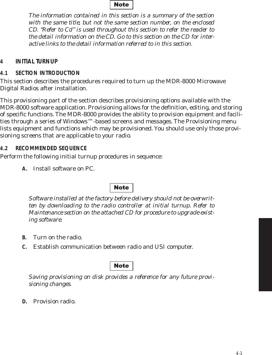
![4-44Figure 4 - 24 MCS-11 ProvisioningAUDIO 1:AUDIO 2:RS-232MCSTMNChannel3MCS TransportRF/RptrPPP TransportRF/RptrChannel E-LeadOff -GNDLevel M-Lead0/0 NormAddressA12AJ308/J309 Input ClocksRSSJ310 Modem J308/J309 TerminationRDS/RAS/RCDChannel 1 Channel 2 Repeater D/1Channel E-Lead All Call DetectOff -GNDDTMFLevel M-Lead 2-Wire Auto Squelch0/0 Norm 00AddressRadio Configuration Service Channel WaySide DS1 FacilitiesDS3 FacilitiesAlcatel User Interface – [System, DS3, and DS1 Provisioning -- MDR-8000 DS3]File View Setup OptionsF6PerformanceAlarm StatusF4Analog Monitor Station AlarmF7ProvisioningF9User ControlF8F5Prov. SaveF3Thursday, March 7, 2000 1:27:15 PM USI Version R1.03 Controller Version R1.03 MDR-8000 3-DS3ELMC Address:ELMC Description:J7914DURANGOLOCAL DS3 PROVISIONINGCommunicating***Allows user to enter the NE MCS address. The following list provides a valid address for each station:ALPHA NUMERIC ALPHAA 1 Athrough through throughH 16 FMDR-103906/23/05NoteA default MCS-11 address (A1A) is assigned automatically. A different unique address must be entered for each radio to prevent concurrent responses to poll from more than one radio with the same address. If multiple responses are received, the response data is invalid.Check RDS/RAS/RCD to allow controller to respond when Remote Detail Scanner (RDS), Remote Analog Scanner (RAS), or Remote Control Decoder (RCD) is polled. If this operation is not checked, controller does not respond when RDS, RAS, or RCD is polled.Check RSS to allow Controller to respond when Remote Station Scanner (RSS) is polled. If this option is not checked, Controller does not respond when RSS is polled.Un-check J310 Modem to enable XMT, RCV, and Output Clocks. Check J310 Modem to disable XMT and RCV Clocks. All clocks to be provided by external modem.Check MCS-11 J309 Termination to enable resistive termination at the end of an MCS-11 "daisy chain". Un-check J310 Termination for stand-alone applications or when MDR-8000 is just a link in a daisy chain.Check J308/J309 Input clocks if radio syncs off XMT and RCV clocks supplied by external source (such as another radio). Un-check J308/J309 Input clocks if radio is providing XMT and RCV clocks for other radios to sync on.](https://usermanual.wiki/Alcatel-USA/8702-50.User-manual-02/User-Guide-1270259-Page-54.png)
![4-46Figure 4 - 26 ELMC Remote Time-Out Constant Provisioning Remote Time-Out Constants -- MDR-8000Select a value in the following list to change the current remote timeoutOK Cancel3 secs4 secs5 secs6 secs7 secs8 secs9 secs10 secsCurrent time-out is 3 secsAlcatel User Interface - [Alarm Status -- MDR-8000 OC3]File View Setup OptionsREMOTE STATUS ALARMRetrieving ProvisioningELMC Address [F8]:ELMC Description:DURANGOJ7914A BTRANSMITTRANSMITTERSTATUSA BRECEIVERA BCOMMONRECEIVERSTATUSI/OPWRSTATUSF6PerformanceAlarm Status Analog MonitorF5Station AlarmF7ProvisioningF9AcknowledgeF3User ControlF8✓F4LMW-4024A08/08/02SELECT TIME LOCALLY FOR ELMC RESPONSE TO A REQUEST FOR STATUS BEFORE TRYING AGAIN. SELECT SHORTER TIME (5 SECS) FOR SHORTER SYSTEMS (10 HOPS OR LESS). SELECT LONGER TIME (10 SECS) FOR SYSTEMS WITH 10 HOPS OR MORE.MESSAGE DISPLAYED FOR LENGTH OF TIME SELECTED DURING TIME LOCAL RADIO IS ATTEMPTING TO COMMUNICATE WITH REMOTE ADDRESS VIA ELMC.MESSAGE DISPLAYED FOR LENGTH OF TIME SELECTED IF THERE IS NO RESPONSE TO REQUEST FOR STATUS/CONTROL/PROVISIONING.No ReportNoteIf the time-out value selected is too short, there may not be enough time for the remote controller to respond before the requesting controller times out, resulting in a constant No Report. ELMC response time delay is a function of controller circuitry and is not linear. Always start with longer time-out, then reduce time to an acceptable value.](https://usermanual.wiki/Alcatel-USA/8702-50.User-manual-02/User-Guide-1270259-Page-56.png)
![4-48Figure 4 - 28 Alarm Names ProvisioningDS3 screen is shown. DS1/E1 and OC3/STM-1 alarm names provi-sioning is similar.Alcatel User Interface – [Provisioning MDR-8000 OC3]File View Setup OptionsUser ControlF8F6PerformanceAlarm StatusF4Station AlarmF7 F9Prov. SaveF3 F5Analog Monitor PasswordF11LOCAL DS3 PROVISIONINGCommunicating***ELMC ADDRESS:ELMC ADDRESS:S302LMW-506803/29/03ALARM #ALARM NAMES[1]STATION ALARM #2[2]STATION ALARM #3[3]STATION ALARM #4[4]STATION ALARM #5[5]STATION ALARM #6[6]STATION ALARM #7[7]STATION ALARM #8[8]STATION ALARM #9[9]STATION ALARM #10[10]STATION ALARM #11[11]STATION ALARM #12[12]ALARM #ALARM NAMESSTATION ALARM #13 [13]STATION ALARM #14[14]STATION ALARM #15[15]STATION ALARM #16[16]ALARM #ALARM NAMESDS301 -- MDR-8000 DS3DS301 -- MDR-8000 DS3 OK Cancel ApplySTATION ALARM #1Monday, August 6, 2001 2:11:32 PM MDR-8000 DS3 Controller Version R1.032. SELECT ALARM3. BACKSPACE TO DELETE AND TYPE IN NEW ALARM NAME1. SELECT RADIOCLICK HERE TO SAVEAVAILABLE IF RADIO IS PROVISIONED STATION ALARM 13-16 FOR SYSTEM ALARM ON RADIO CONFIGURATION PROVISIONING SCREEN.HIDDEN IF RADIO IS PROVISIONED TBOS DISPLAY 1-8.Note](https://usermanual.wiki/Alcatel-USA/8702-50.User-manual-02/User-Guide-1270259-Page-58.png)

![5-44Figure 5 - 17 Restoring PA Output Power Using Power MeterPWR MONXMT PWRALMON LINEI CARR NULLXMT LVLADJFREQ CONTQ CARR NULLTRANSMITTERRFOUTXTALMONRFMONREAD [X.X dBm] FOR [XX.X dBm]AT TOP OF RACK READ X.X dBm FOR XX.X dBm AT TOP OF RACKDCMONGND10.5V DCPWR ALMTEMP ALMDC MON ADJPWR ALM ADJPOWER AMPLIFIERRFINRFMONREAD X.X dBm FOR XX.X dBm AT TOP OF RACKPOWERSENSOR50 OHMPOWERMETERNTFCMDR-1173 09/08/05aConnect power meter with 50 OHM power sensor to RF MON connector on PA.cWhile monitoring power meter, adjust XMT LVL ADJ control on XMTR for READ X.X dBm level on PA label. This returns PA output level original level.bMeasure RF monitor level on power meter.dDisconnect test equipment.](https://usermanual.wiki/Alcatel-USA/8702-50.User-manual-02/User-Guide-1270259-Page-102.png)
![5-45Figure 5 - 18 Restoring PA Output Power Using DVMaConnect DVM to DC MON (+) test point and GND on PA.cWhile monitoring voltage on DVM, adjust XMT LVL ADJ control on XMTR for READ (X.X Vdc) voltage on PA label. This returns PA output level to original level.bMeasure DC monitor level on DVM.dDisconnect test equipment.PWR MONXMT PWRALMON LINEI CARR NULLXMT LVLADJFREQ CONTQ CARR NULLTRANSMITTERRFOUTXTALMONRFMONREAD [X.X dBm] FOR [XX.X dBm]AT TOP OF RACK DC MONGND10.5V DCPWR ALMTEMP ALMDC MON ADJPWR ALM ADJPOWER AMPLIFIERRFINDVM+DC MONITOR CALIBRATIONREAD [X.X Vdc] FOR [XX.X dBm] DC MONITOR CALIBRATIONREAD [X.X Vdc] FOR [XX.X dBm] TFCMDR-1174 09/08/05](https://usermanual.wiki/Alcatel-USA/8702-50.User-manual-02/User-Guide-1270259-Page-103.png)
![5-59Figure 5 - 21 XMTR Output Level Calibration (Sheet 4 of 5)MDR-106209/08/05PWR MONXMT PWRALMON LINEI CARR NULLXMT LVLADJFREQ CONTQ CARR NULLTRANSMITTERRFOUTXTALMONRFMONPOWERSENSOR50 OHMPOWERMETERREAD [X.X dBm] FOR [XX.X dBm]AT TOP OF RACK READ [X.X dBm] FOR [XX.X dBm]AT TOP OF RACK EXPECTED OUTPUT LEVEL AT TOP OF STACK(REFER TO FIGURE 9-35 STEP a).MEASURED LEVEL(STEP b).Connect Power Meter with 50 OHM Power Sensor to RF MON connector.oMeasure RF Monitor Level on Power Meter.pMake new label for RF MON.qAttach new label.r](https://usermanual.wiki/Alcatel-USA/8702-50.User-manual-02/User-Guide-1270259-Page-117.png)
![5-60Figure 5 - 21 XMTR Output Level Calibration (Sheet 5 of 5)MDR-106309/08/05PWR MONXMT PWRALMON LINEI CARR NULLXMT LVLADJFREQ CONTQ CARR NULLTRANSMITTERRFOUTXTALMONRFMONDC MONITOR CALIBRATIONREAD [X.X Vdc] FOR [XX.X dBm] DVM+DC MONITOR CALIBRATIONREAD [X.X Vdc] FOR [XX.X dBm] EXPECTED OUTPUT LEVEL AT TOP OF STACKMEASURED LEVEL(STEP b).Connect DVM to PWR MON test point.sRe-check carrier null.wMeasure voltage on DVM.tMake new label.uAttach new label.v](https://usermanual.wiki/Alcatel-USA/8702-50.User-manual-02/User-Guide-1270259-Page-118.png)
![5-71Figure 5 - 26 PA Output Level Calibration (Sheet 5 of 5)Connect DVM to DC MON (+) test point and GND.sCreate new label:uAttach new label over the top of DC MON ADJ.vUsing DC MON ADJ on PA front panel, adjust for voltage on DVM equaling expected level at top of stack multiplied by 0.1.tDC MONGND10.5V DCPWR ALMTEMP ALMDC MON ADJPWR ALM ADJPOWER AMPLIFIERRFINMDR-107109/08/05DVM+ EXAMPLE: EXPECTED LEVEL AT TOP OF STACK = 29 dBm 29 dBm X 0.1 (VOLTS DC/dBm) = 2.9 VOLTS DCDC MONITOR CALIBRATIONREAD [X.X Vdc] FOR [XX.X dBm] DC MONITOR CALIBRATIONREAD [X.X Vdc] FOR [XX.X dBm] EXPECTED OUTPUT LEVEL AT TOP OF STACKREFER TO EXAMPLE ABOVE.MEASURED LEVEL(STEP b).](https://usermanual.wiki/Alcatel-USA/8702-50.User-manual-02/User-Guide-1270259-Page-129.png)