Alcatel USA 0101 Spread Spectrum Wireless ADSL Router User Manual Manual
Alcatel USA Marketing, Inc. Spread Spectrum Wireless ADSL Router Manual
UserManual.wiki
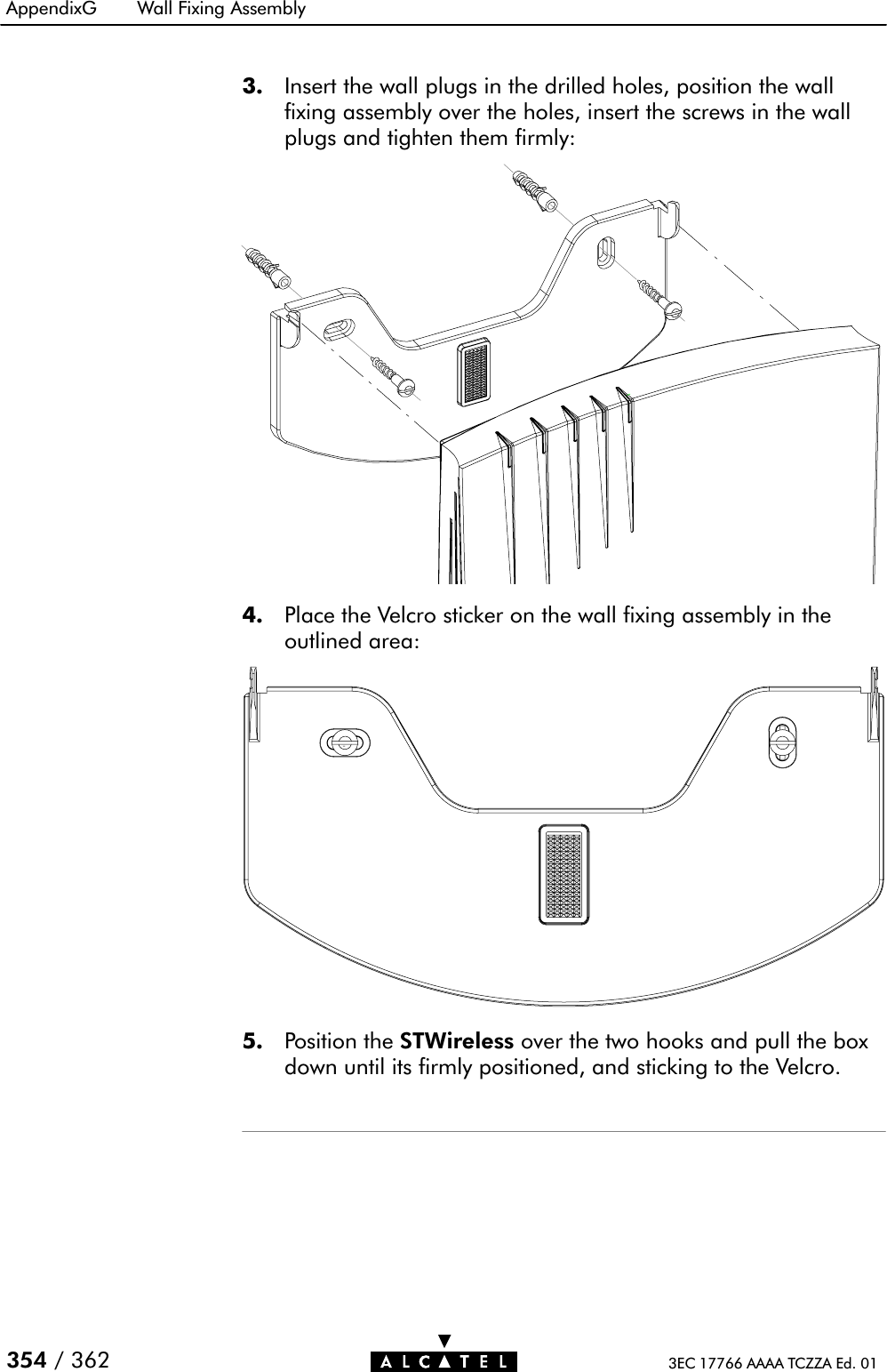
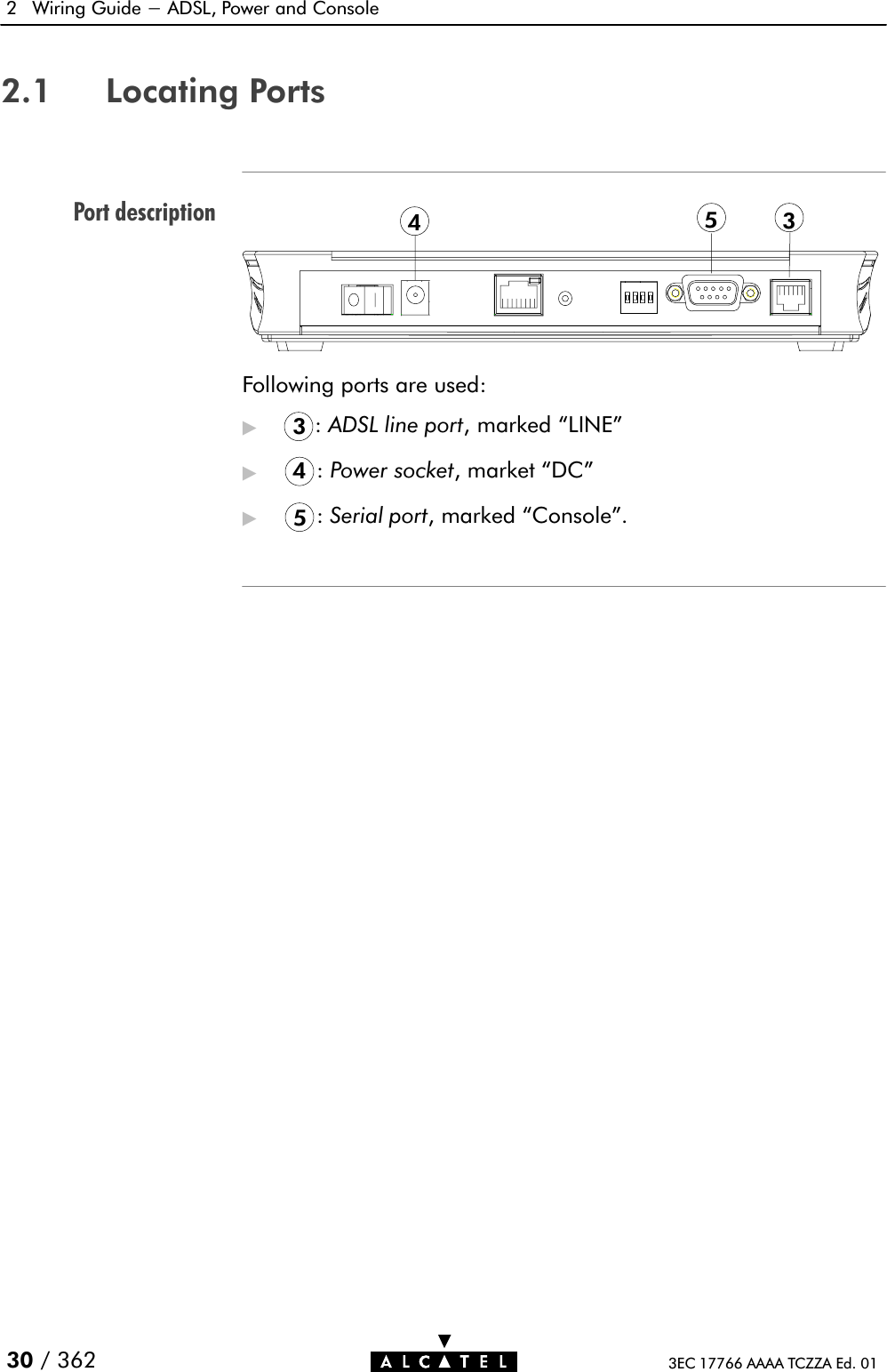
>
Alcatel USA
>
0101 User Manual
Manual
Navigation menu
Upload a User Manual
Namespaces
Wiki Guide
HTML
PDF
Info
Views
User Manual
Discussion / Help
Navigation


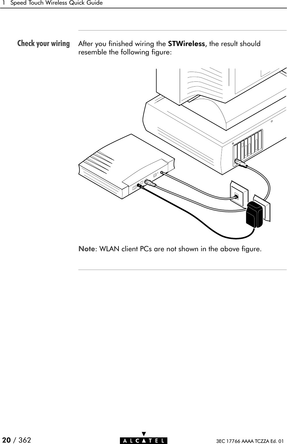


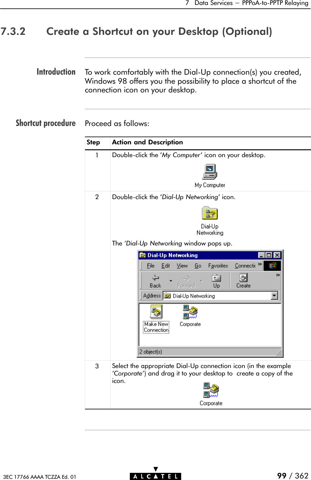

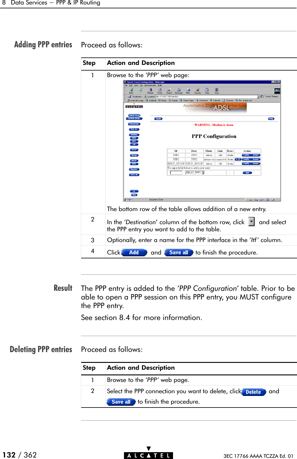


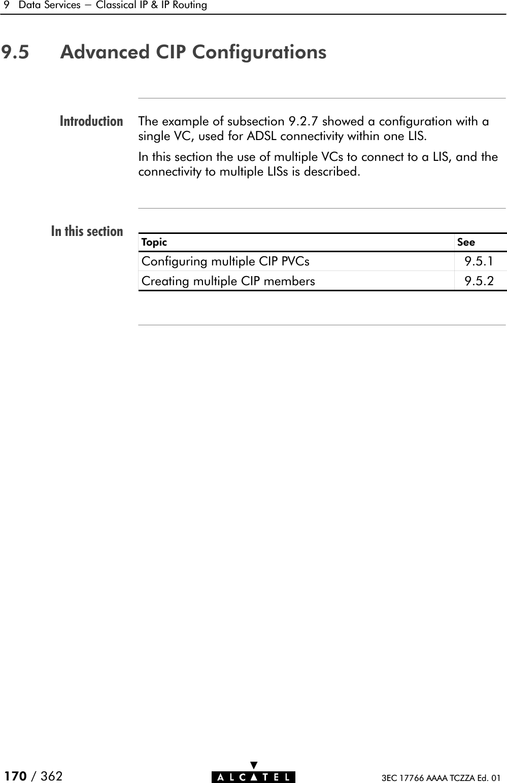
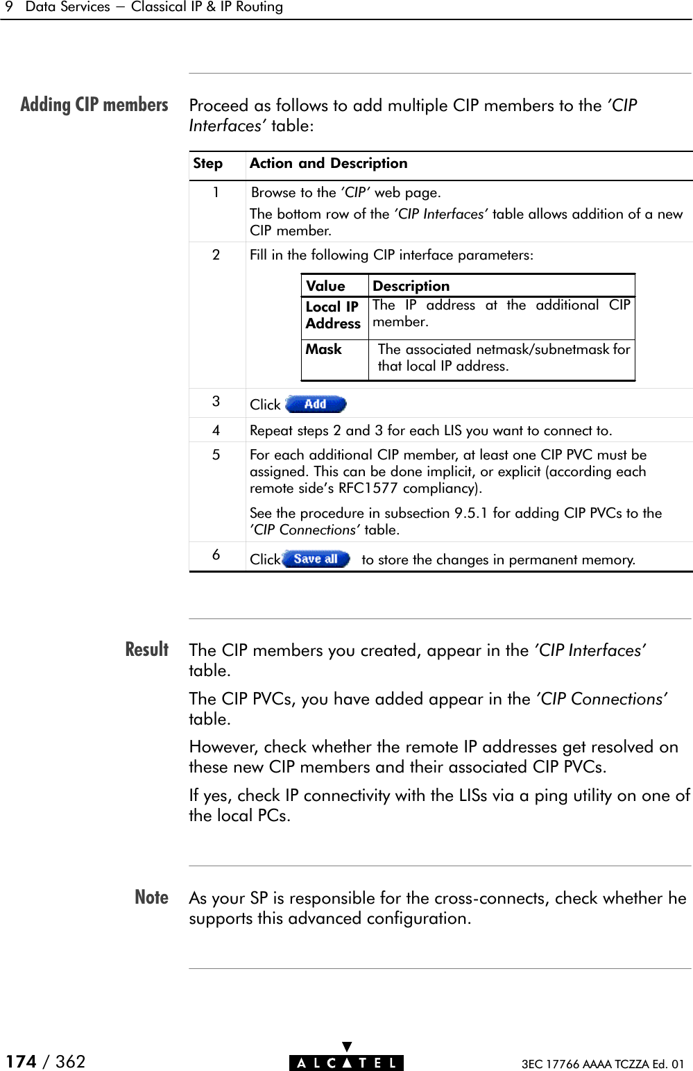


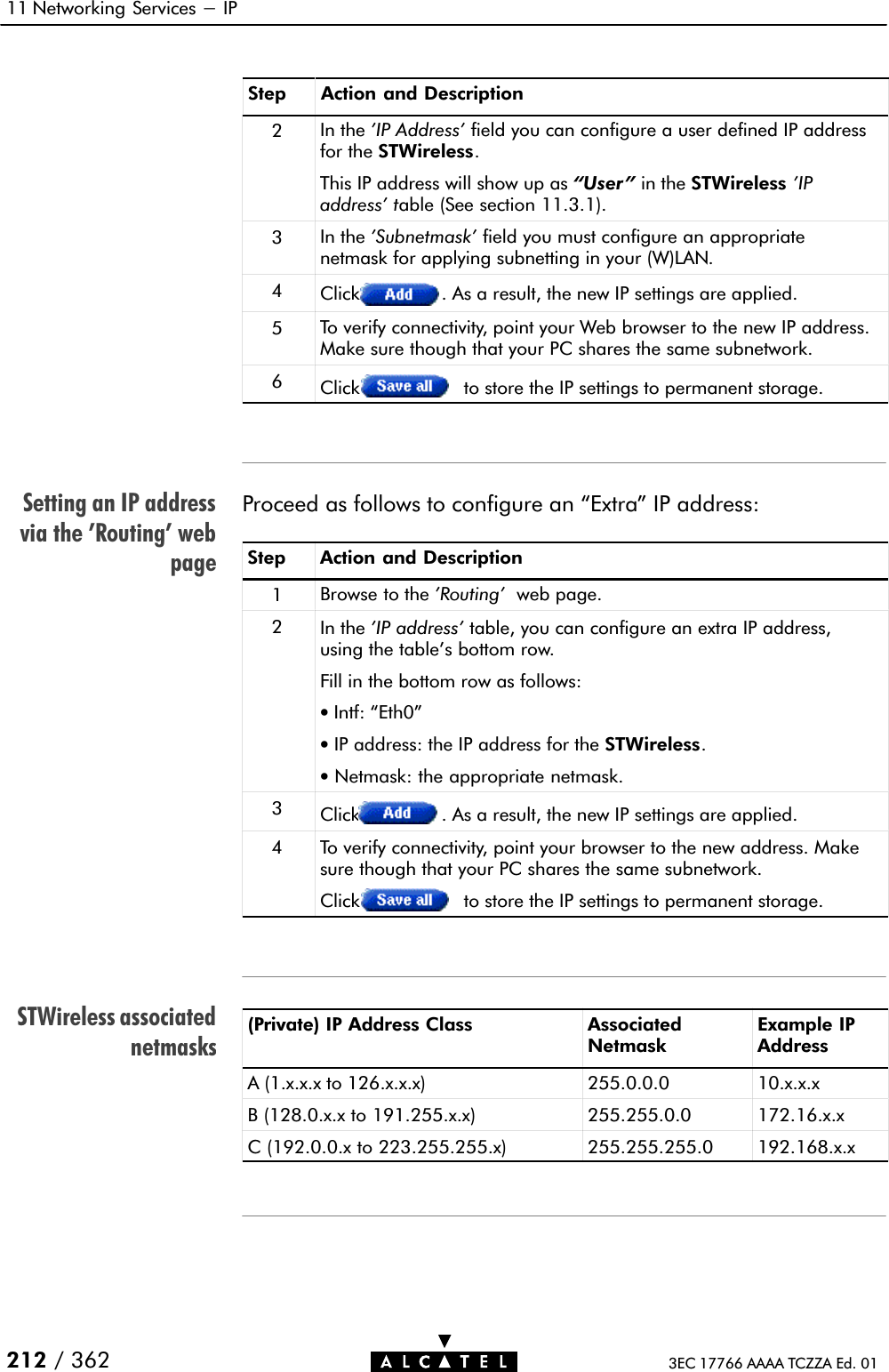


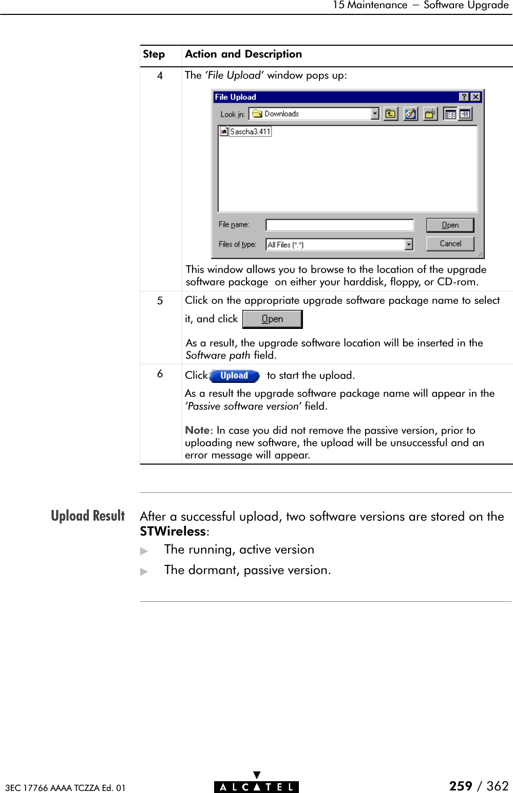


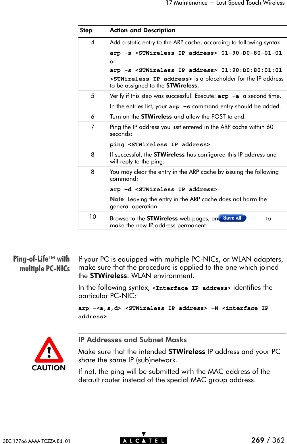

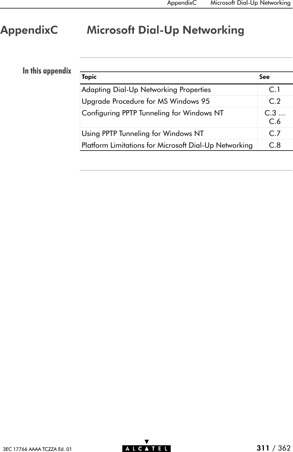
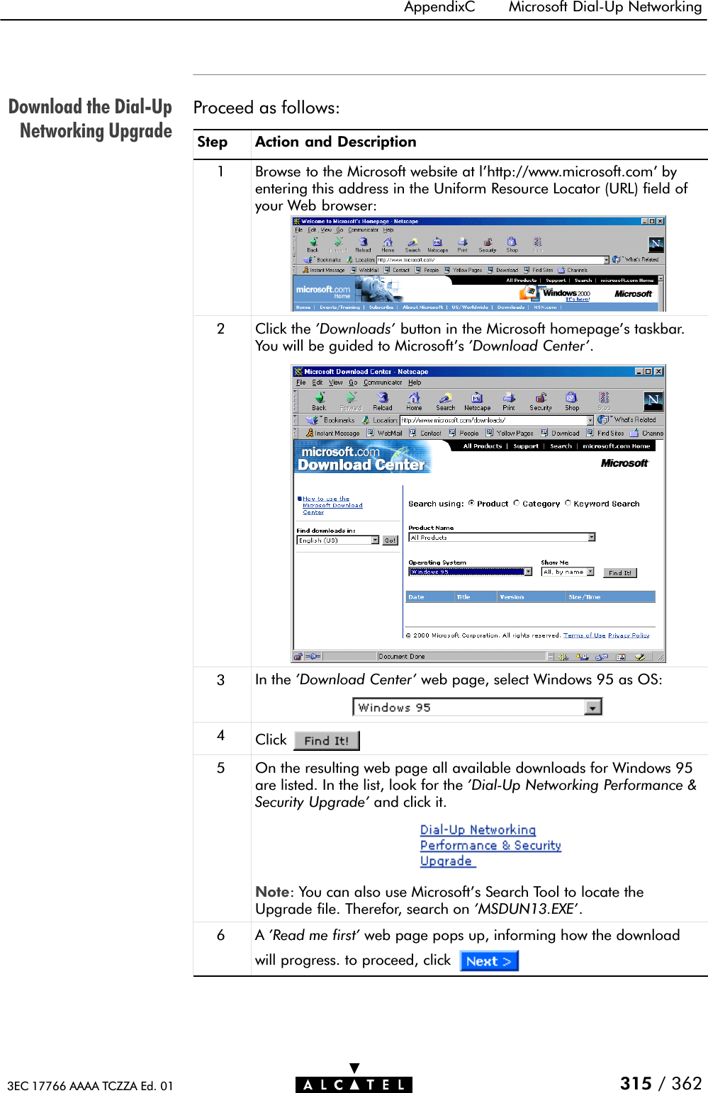
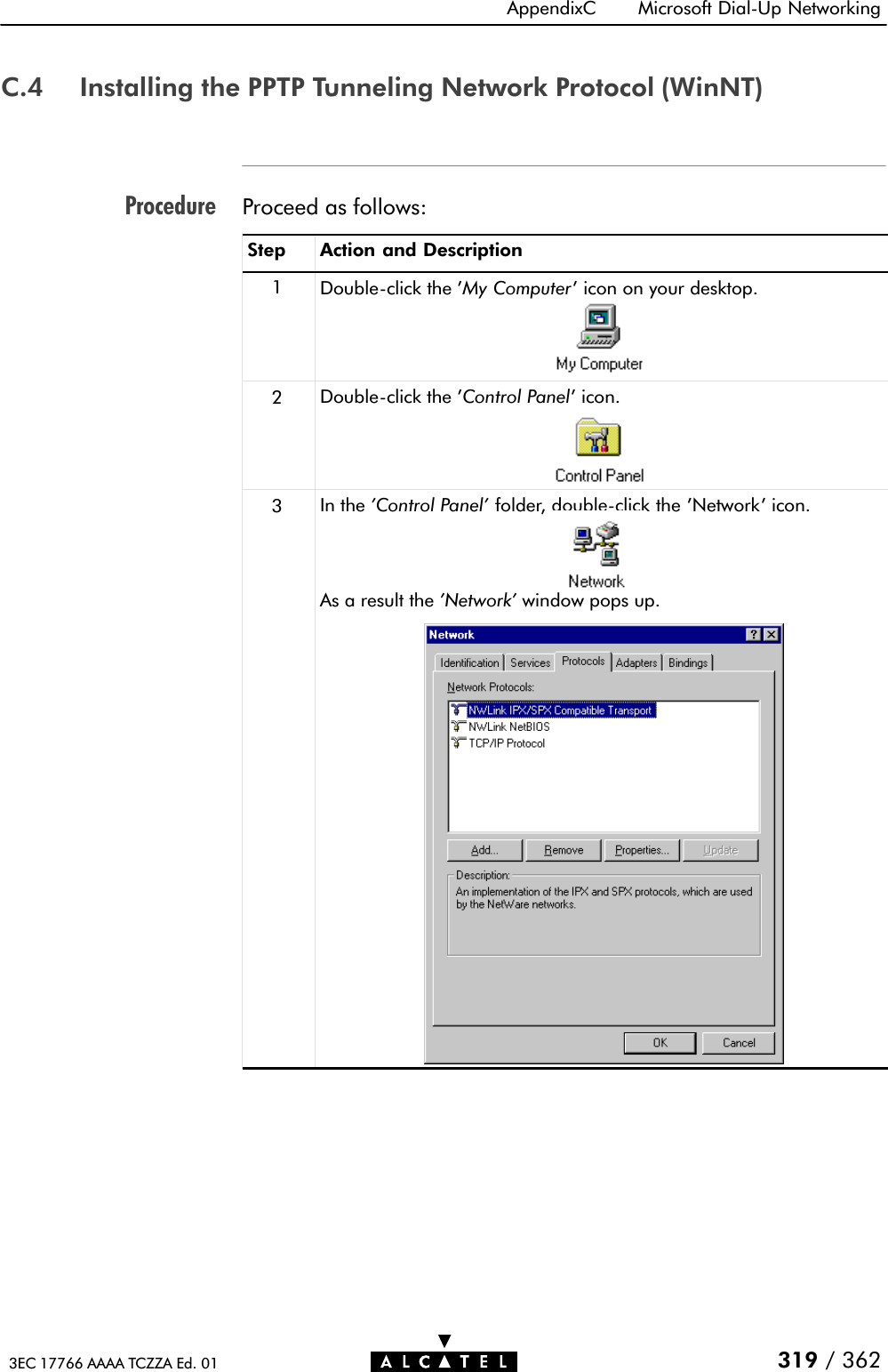
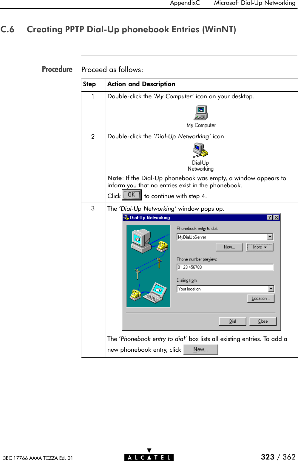
![Closing a TelnetSessionNote19 Maintenance - Speed Touch Wireless Command Line Interface293 / 3623EC 17766 AAAA TCZZA Ed. 01CLI access to your STWireless is released, either via timeout, orby holding down the 'Ctrl' tab and pressing ']'.To quit the Telnet application, enter quit, or hold down the 'Ctrl'tab and press 'C'.You can perform a quick release from the CLI to your OS'sprompt, by holding down the 'Ctrl' tab and pressing 'C' at the CLIprompt.](https://usermanual.wiki/Alcatel-USA/0101/User-Guide-159918-Page-293.png)
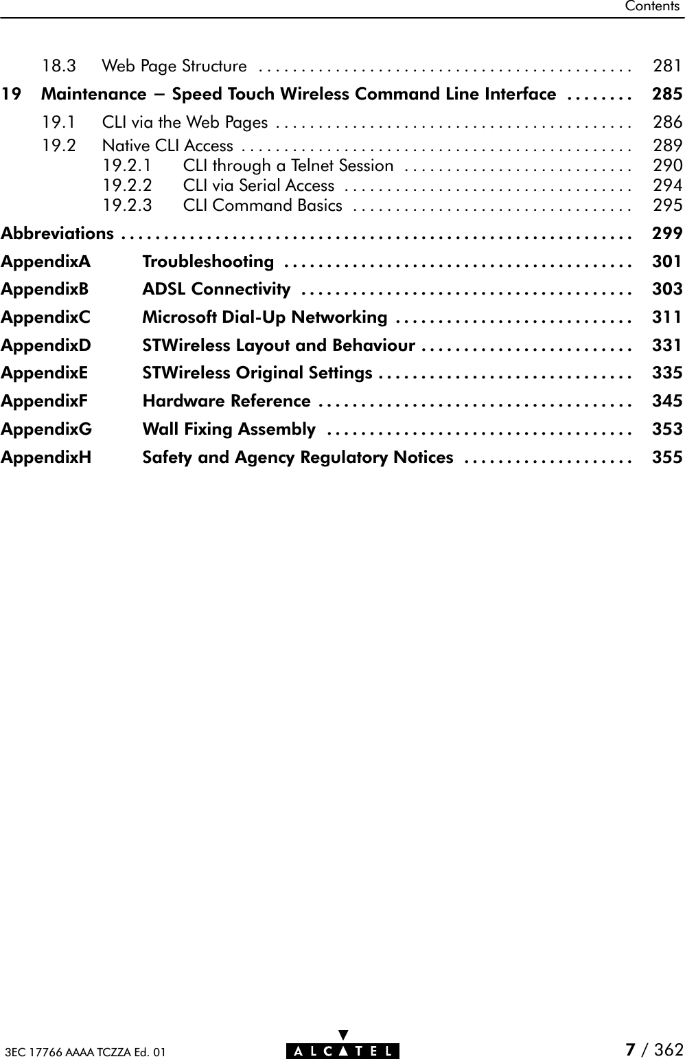
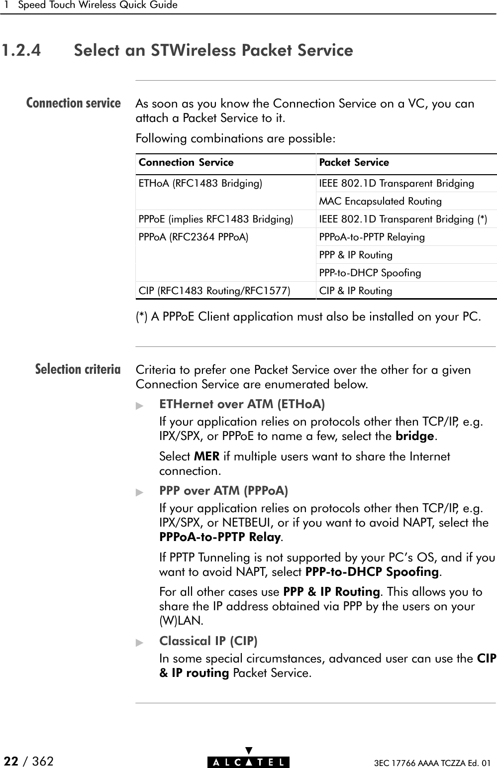
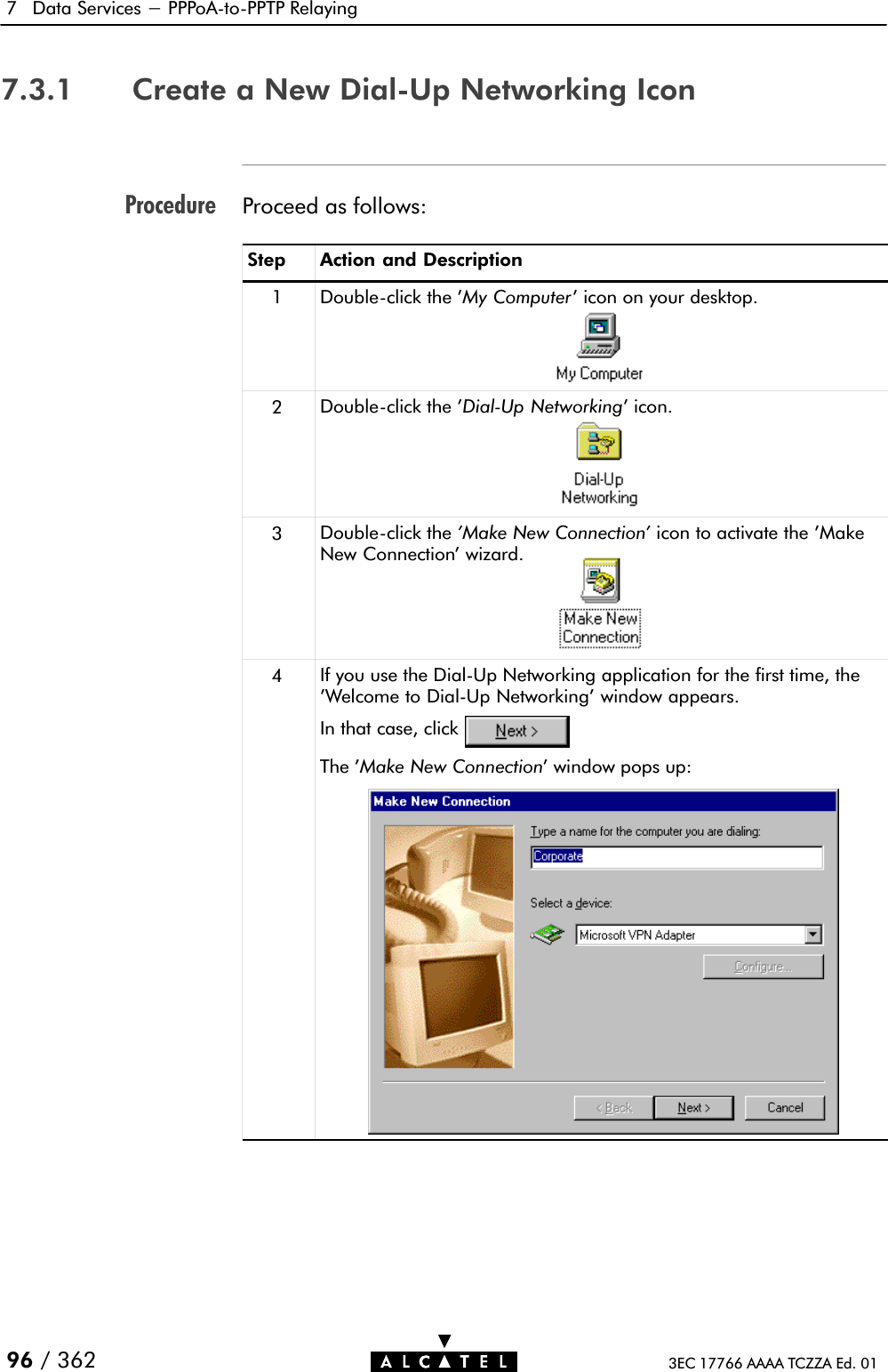
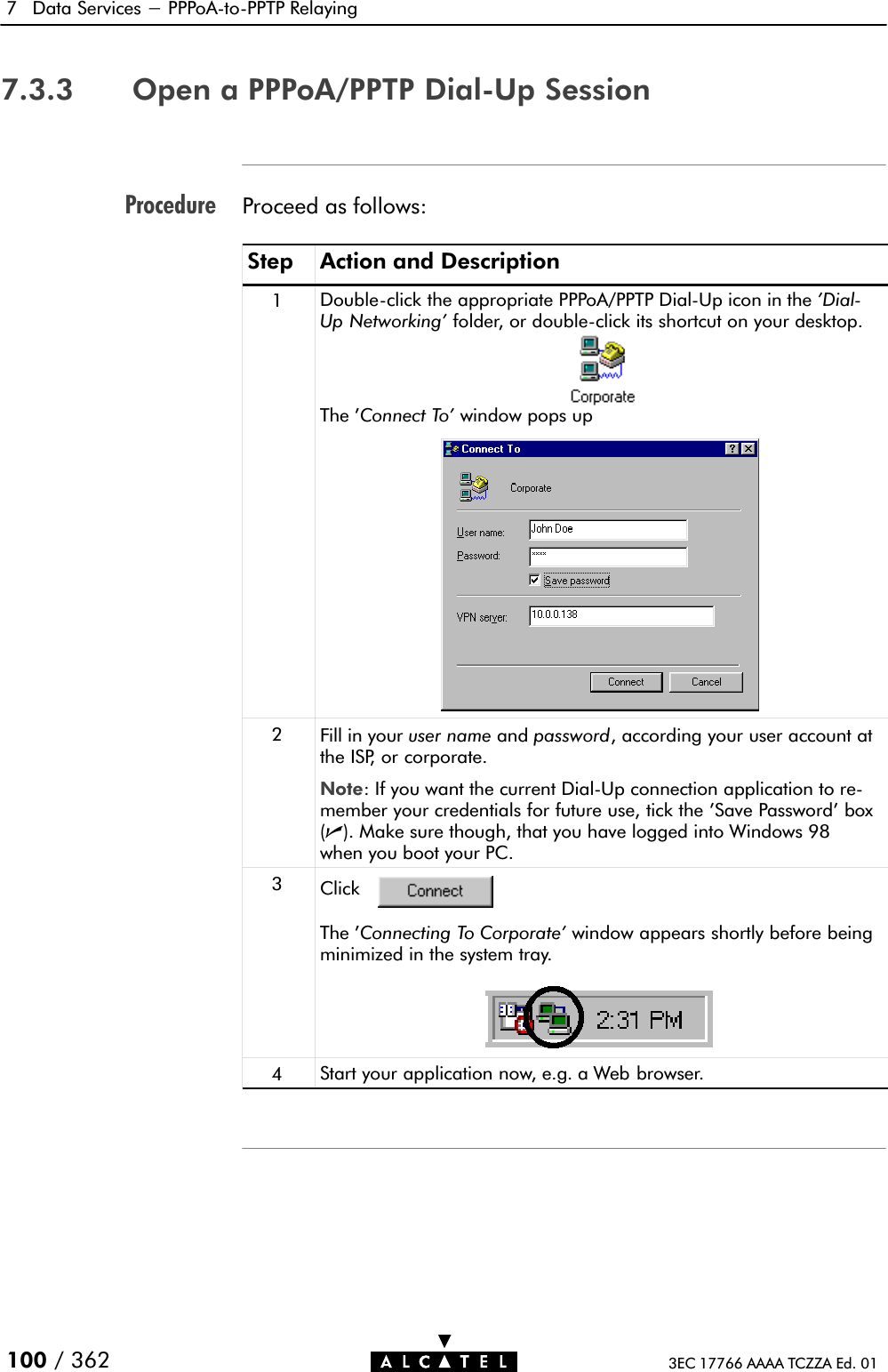
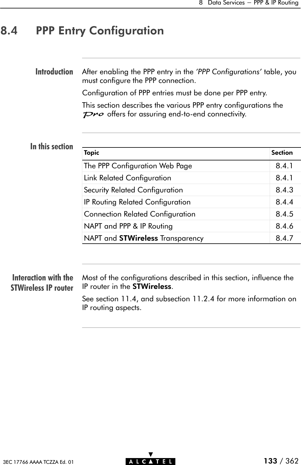
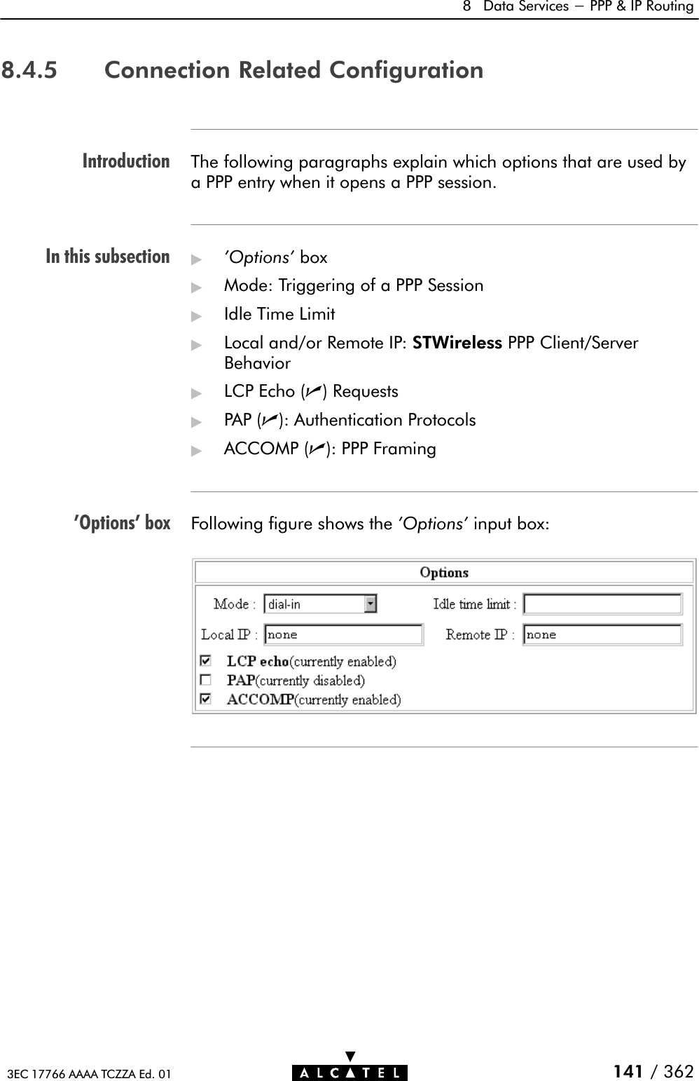
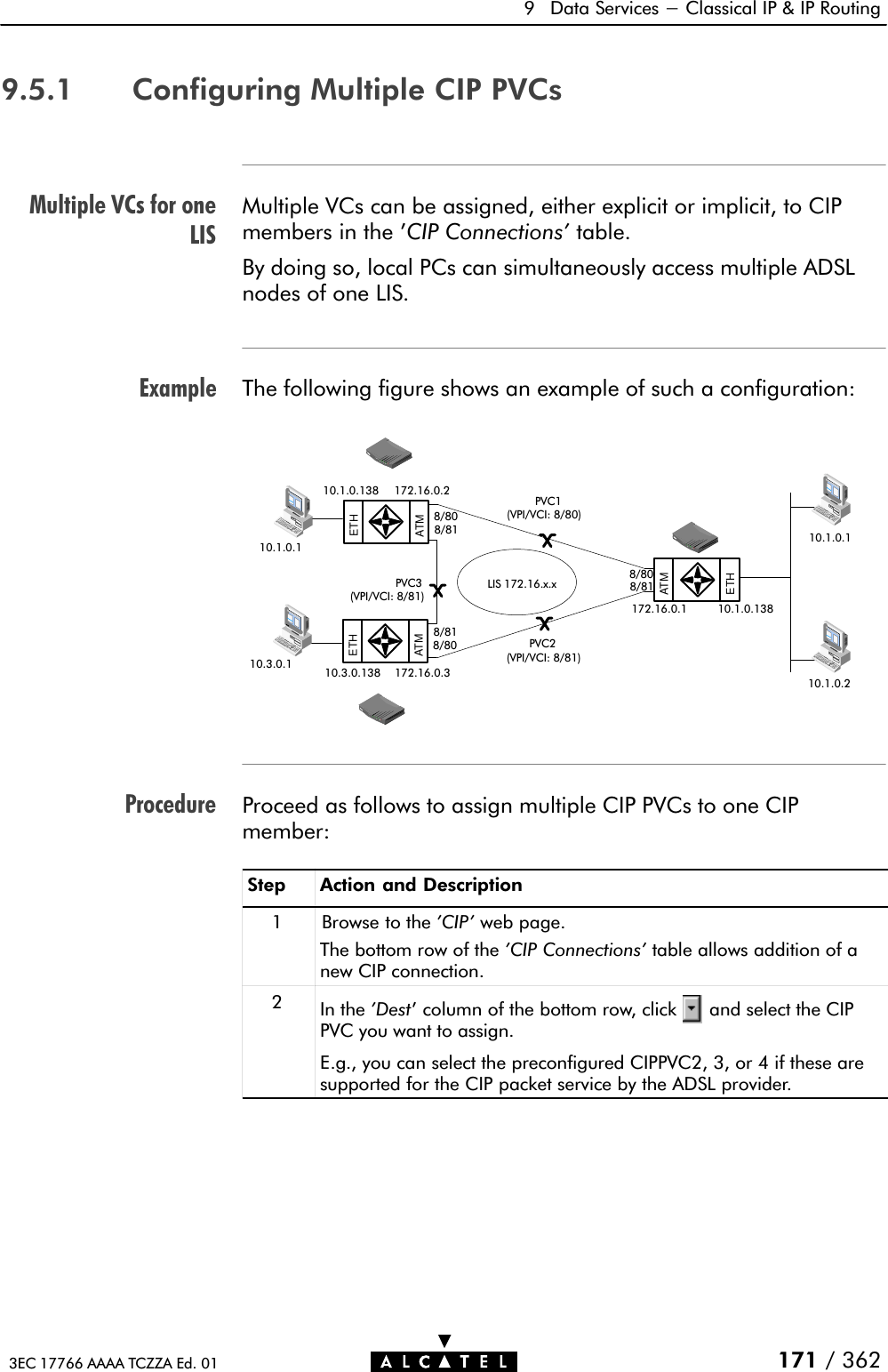
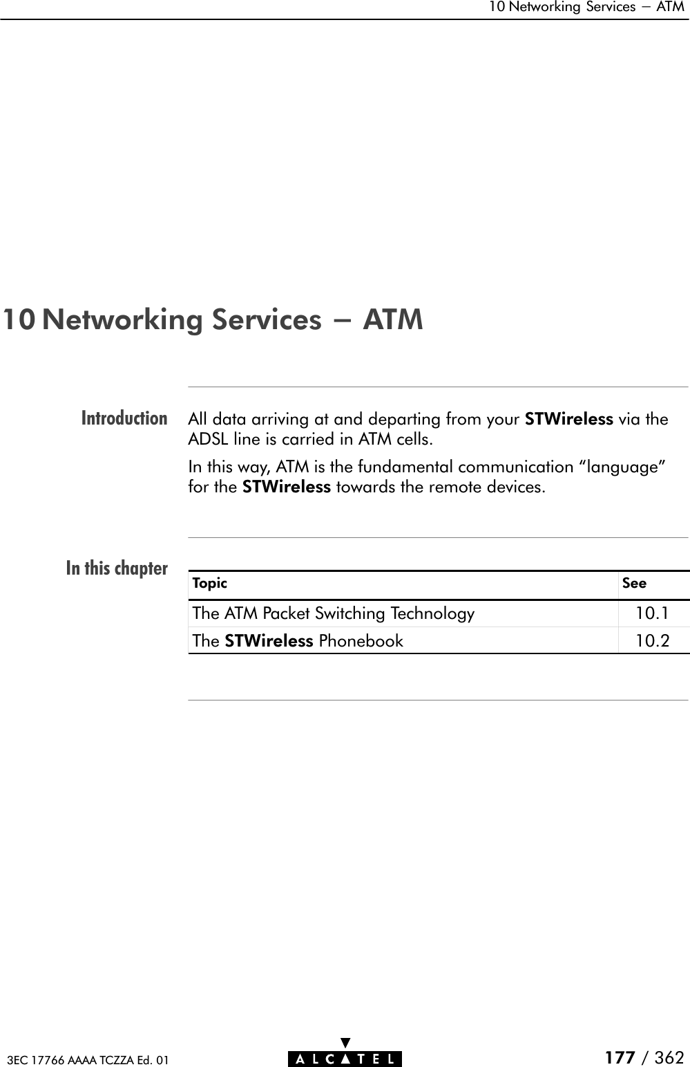
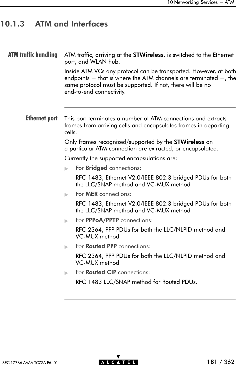
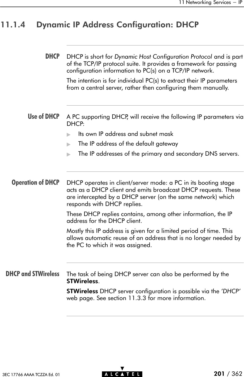
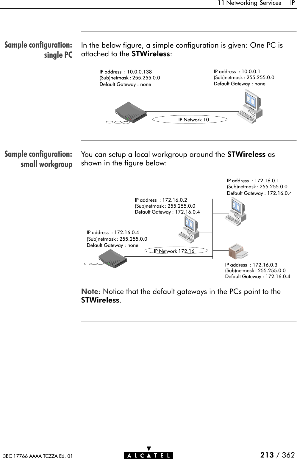
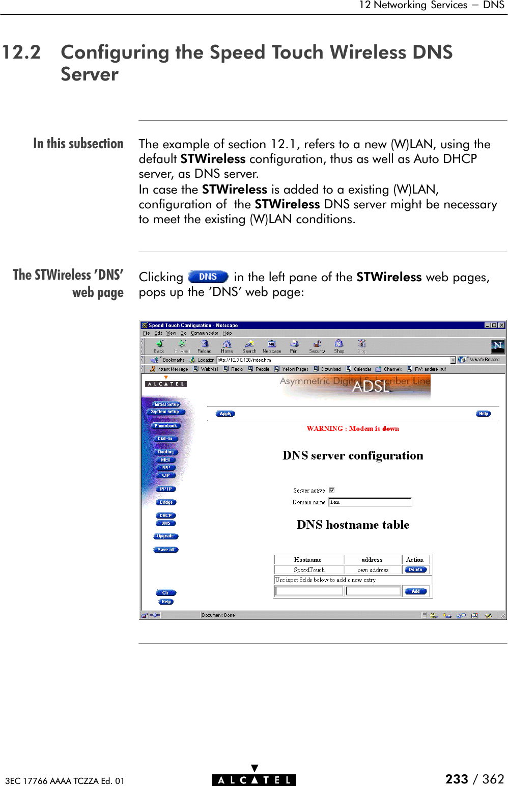
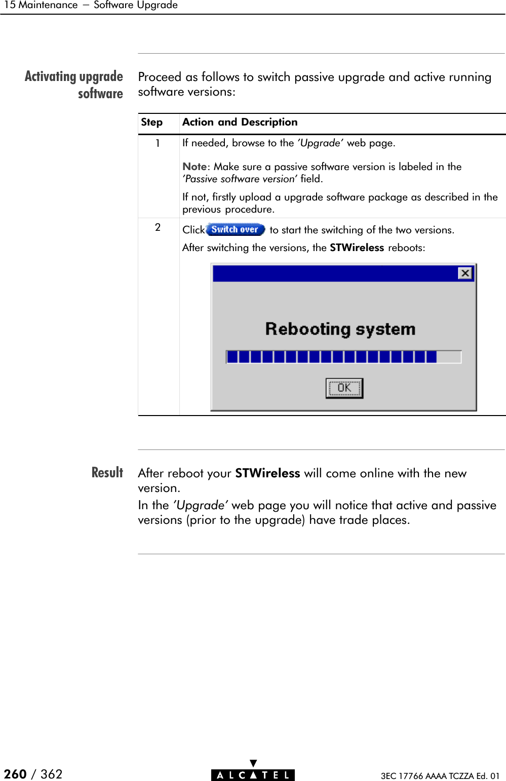
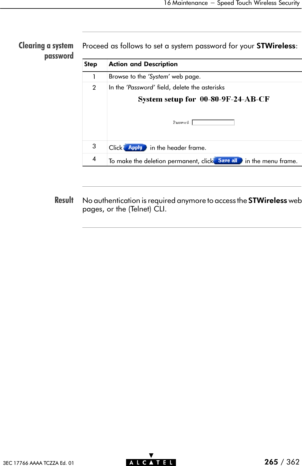
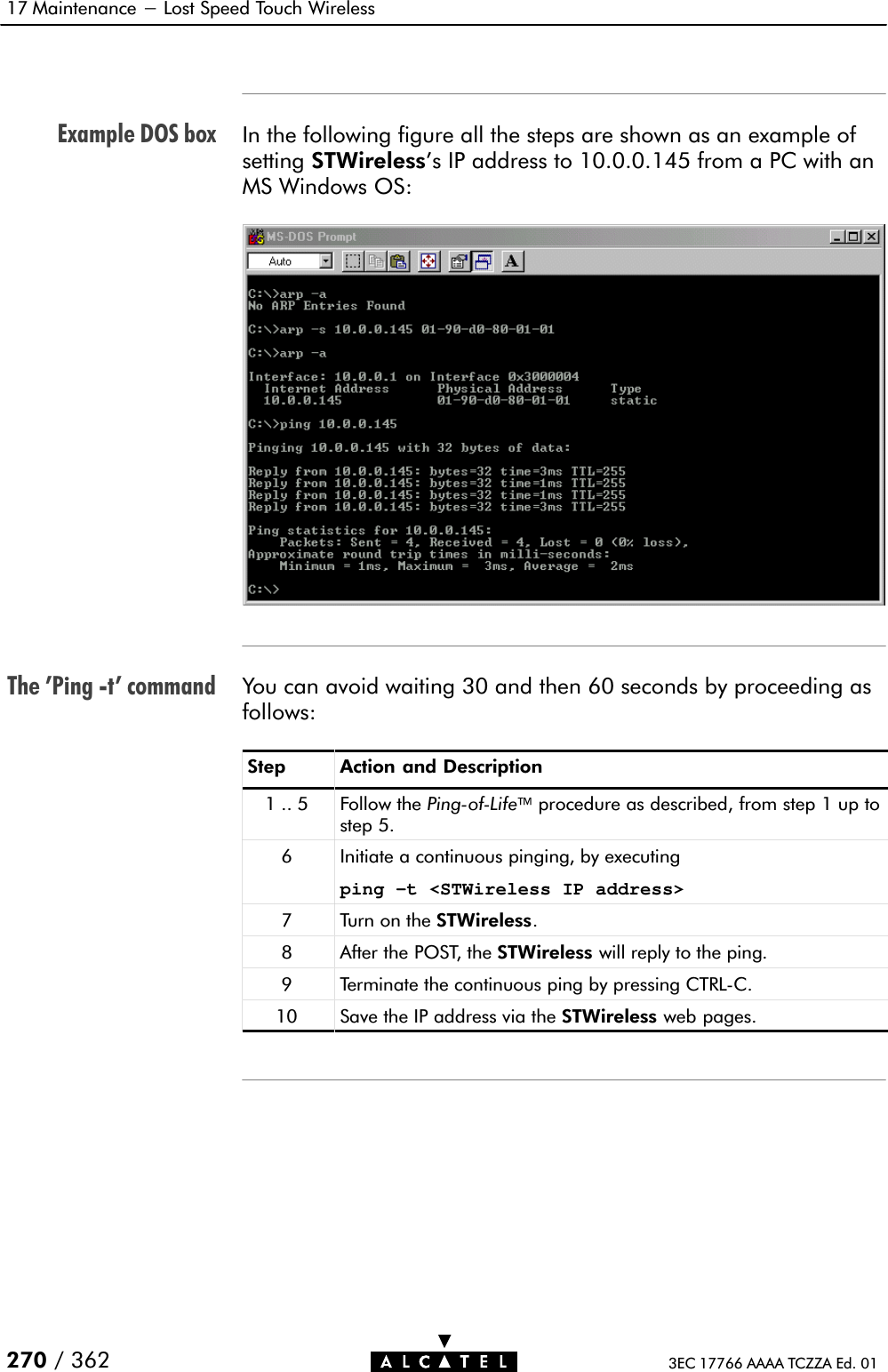
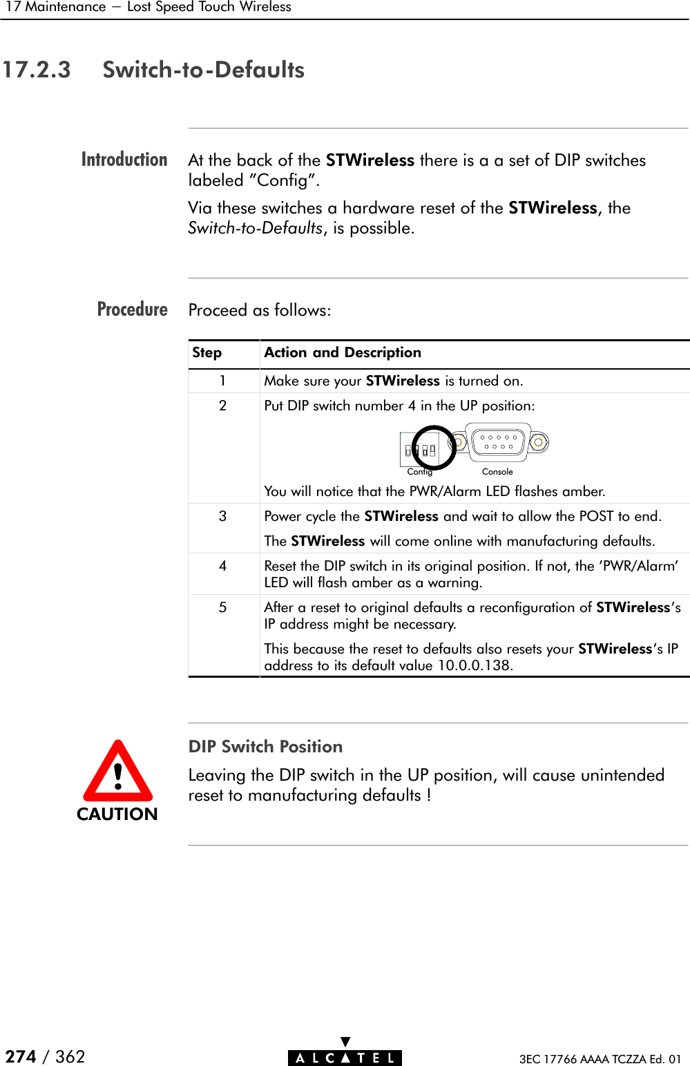
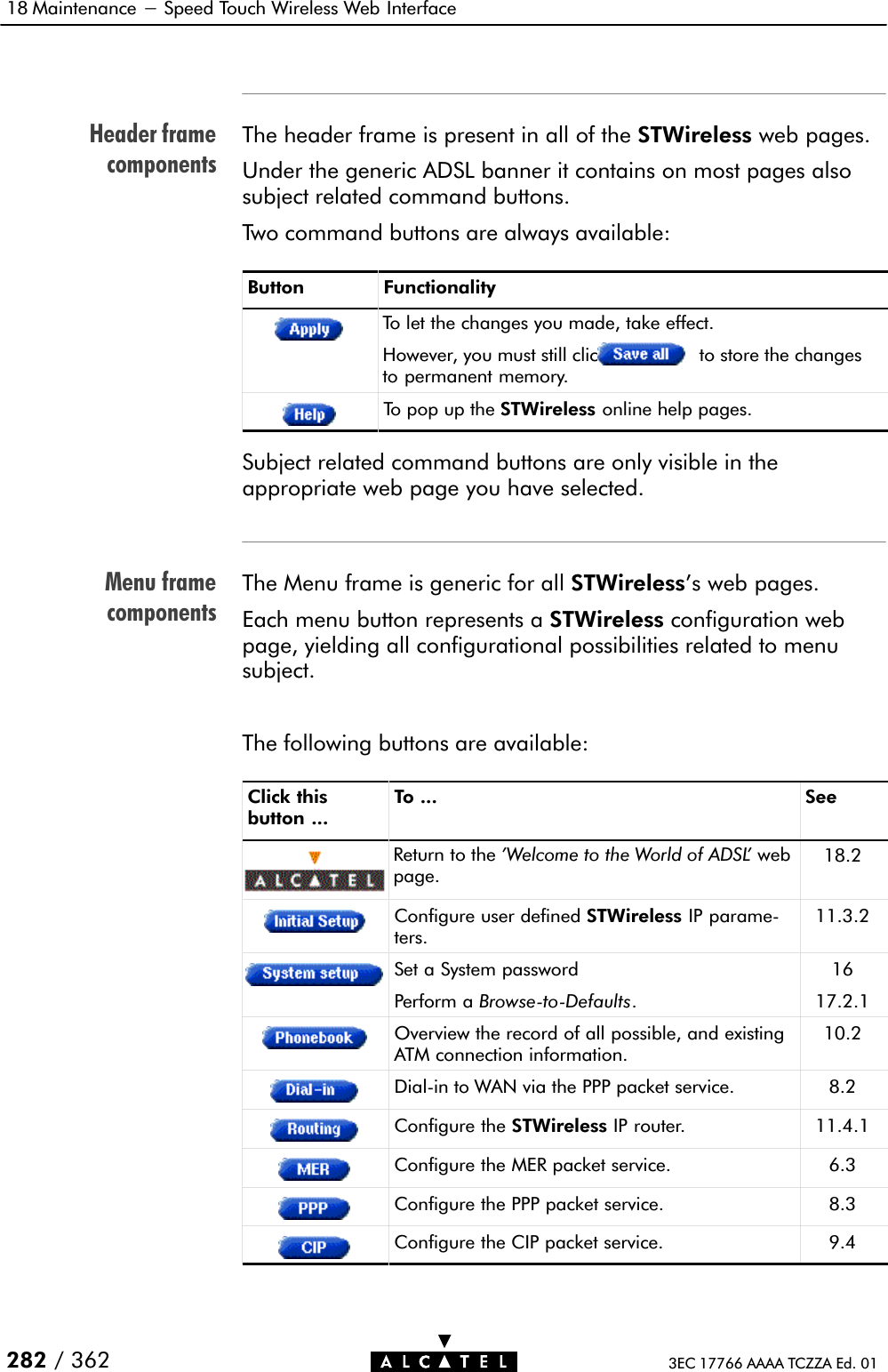
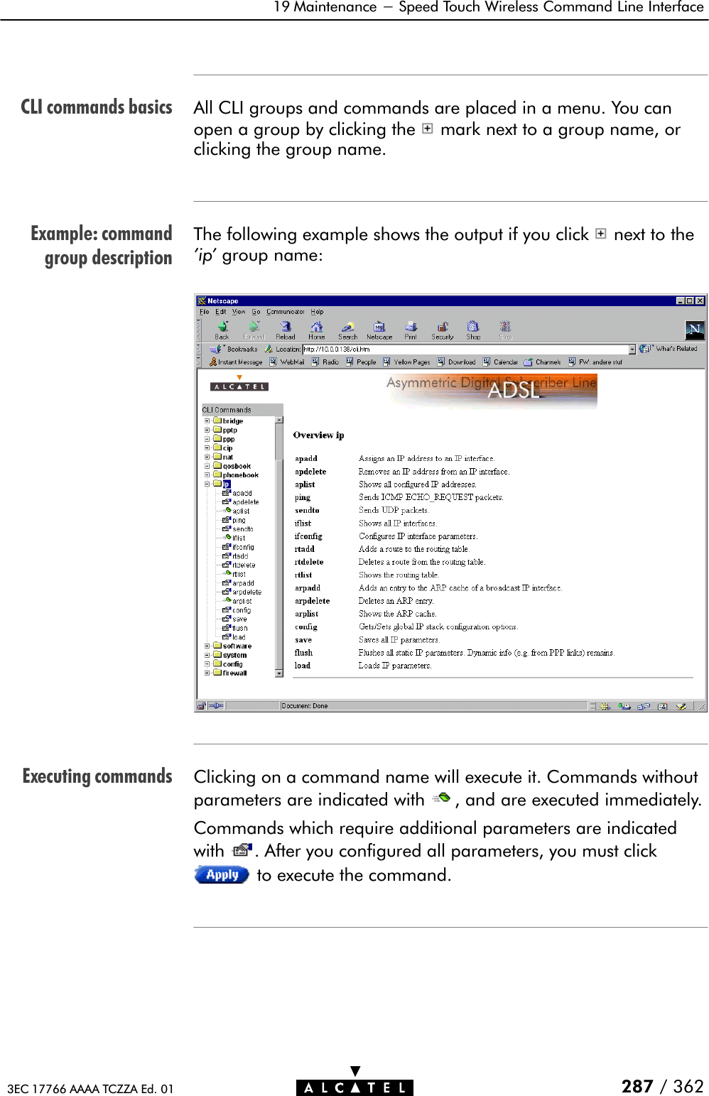
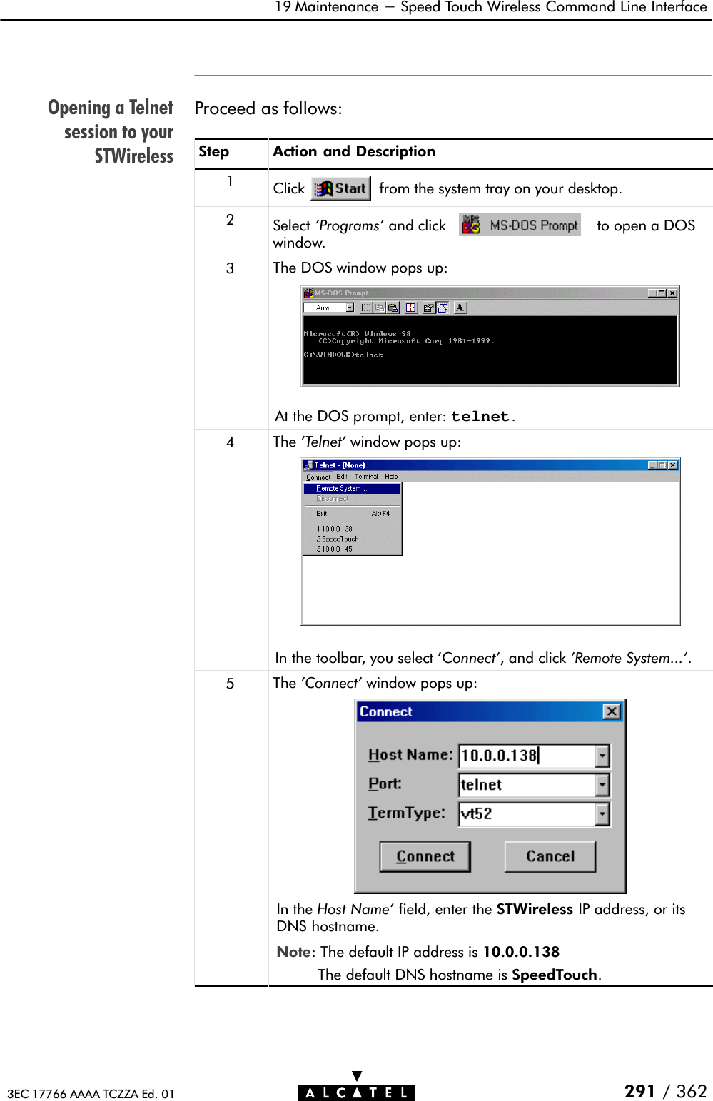
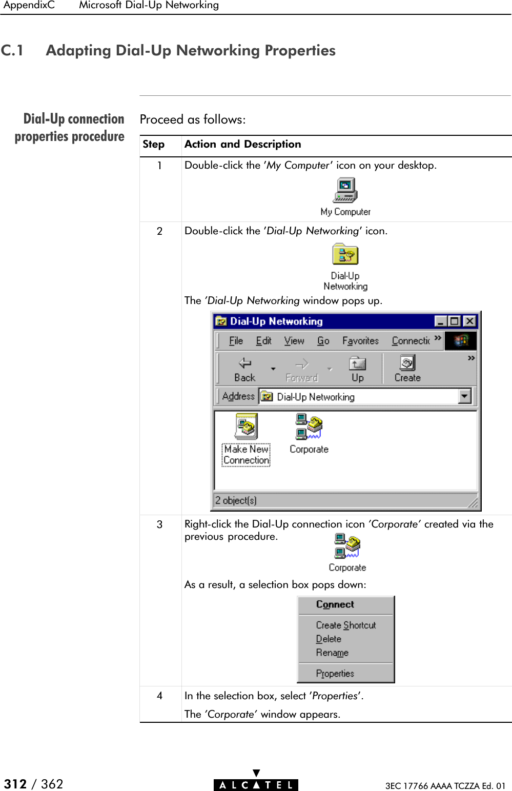
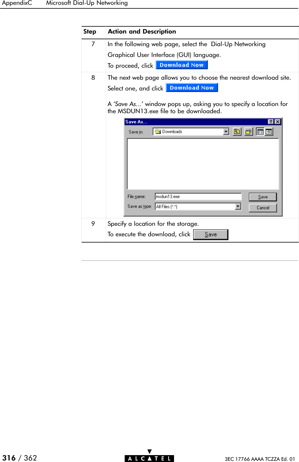
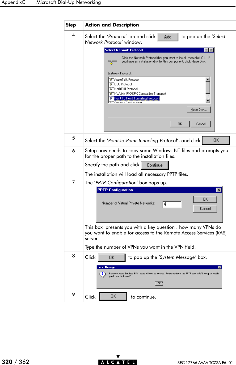
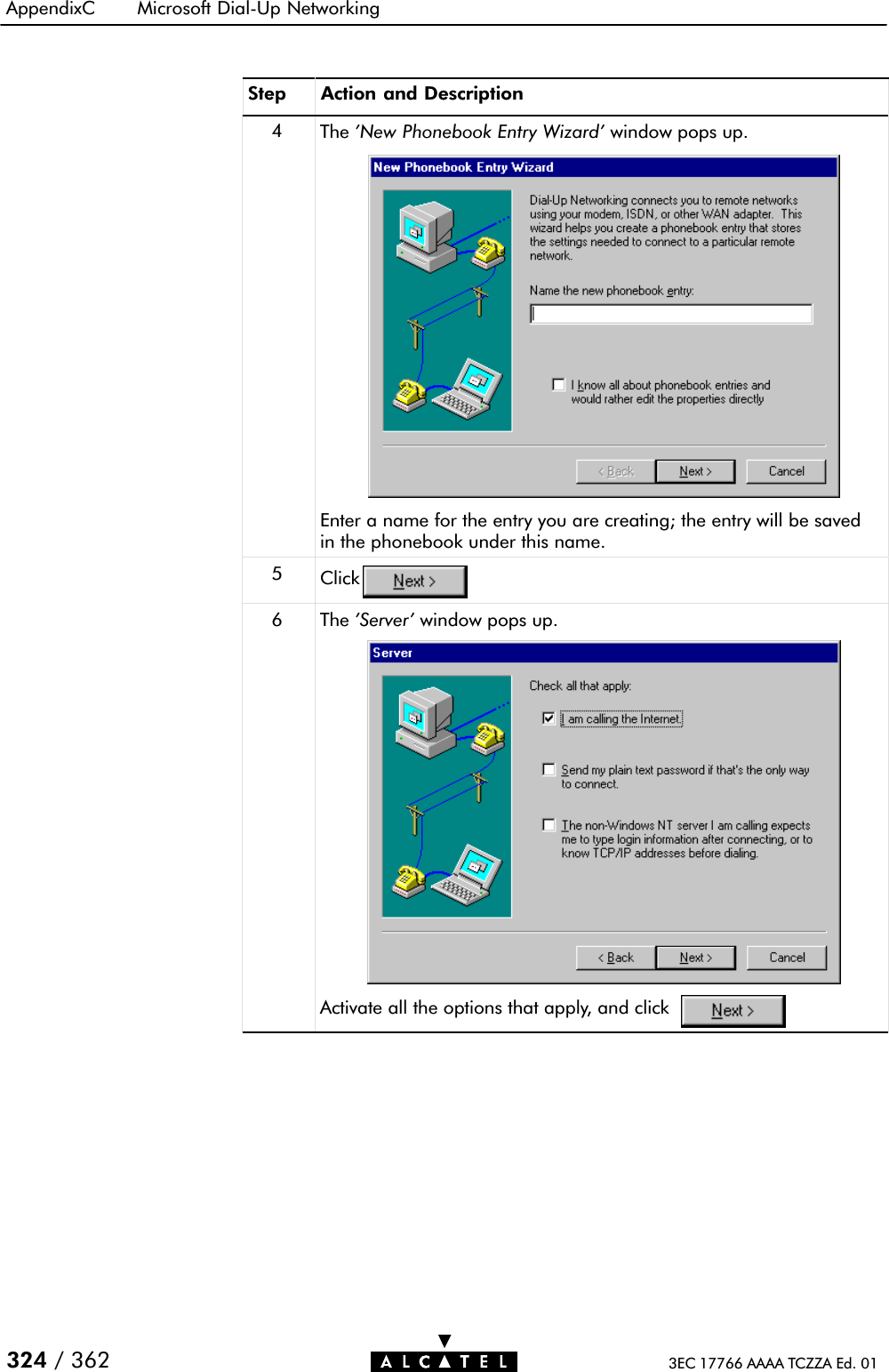
![IntroductionGeneral CLIinformationCLI helpNavigating through CLIlevels19 Maintenance - Speed Touch Wireless Command Line Interface295 / 3623EC 17766 AAAA TCZZA Ed. 0119.2.3 CLI Command BasicsAlthough it is not the aim of this subsection to give a complete overview of all possible configurational STWireless items, thissubsection describes some of the generalities of the native CLIenvironment.Once you accessed your STWireless, you will get the CLI prompt:=>.From this point you can start entering your commands.The CLI access is structured in what is called levels".The => prompt indicates that you are in the root" level of CLI.Typing help at the root prompt shows you the available command groups:=>helpFollowing commands are available :help : Displays this help information? : Displays this help informationexit : Exits group selection... : Exits group selection.Following command groups are available :dhcp dns td atmf merbridge pptp ppp cip natqosbook phonebook ip software systemconfig firewall=>Entering the name of a command group, accesses you to thisspecific level.For example , entering =>config followed by pressing 'Enter',brings you to the 'config' level.This is indicated by its own prompt: [config]=>](https://usermanual.wiki/Alcatel-USA/0101/User-Guide-159918-Page-295.png)
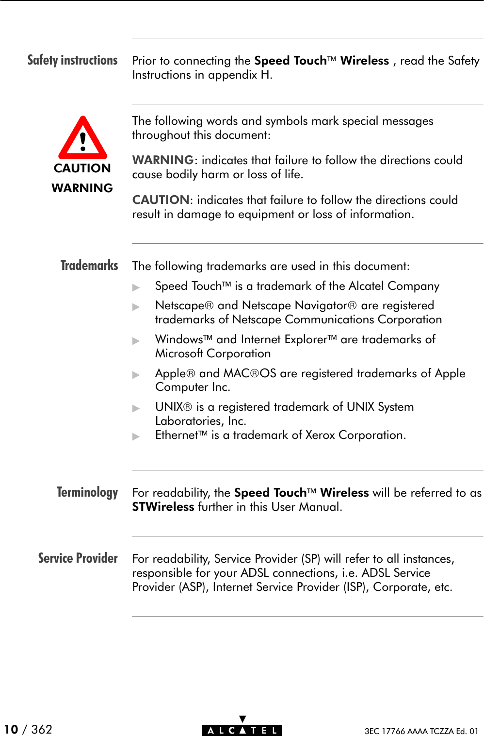
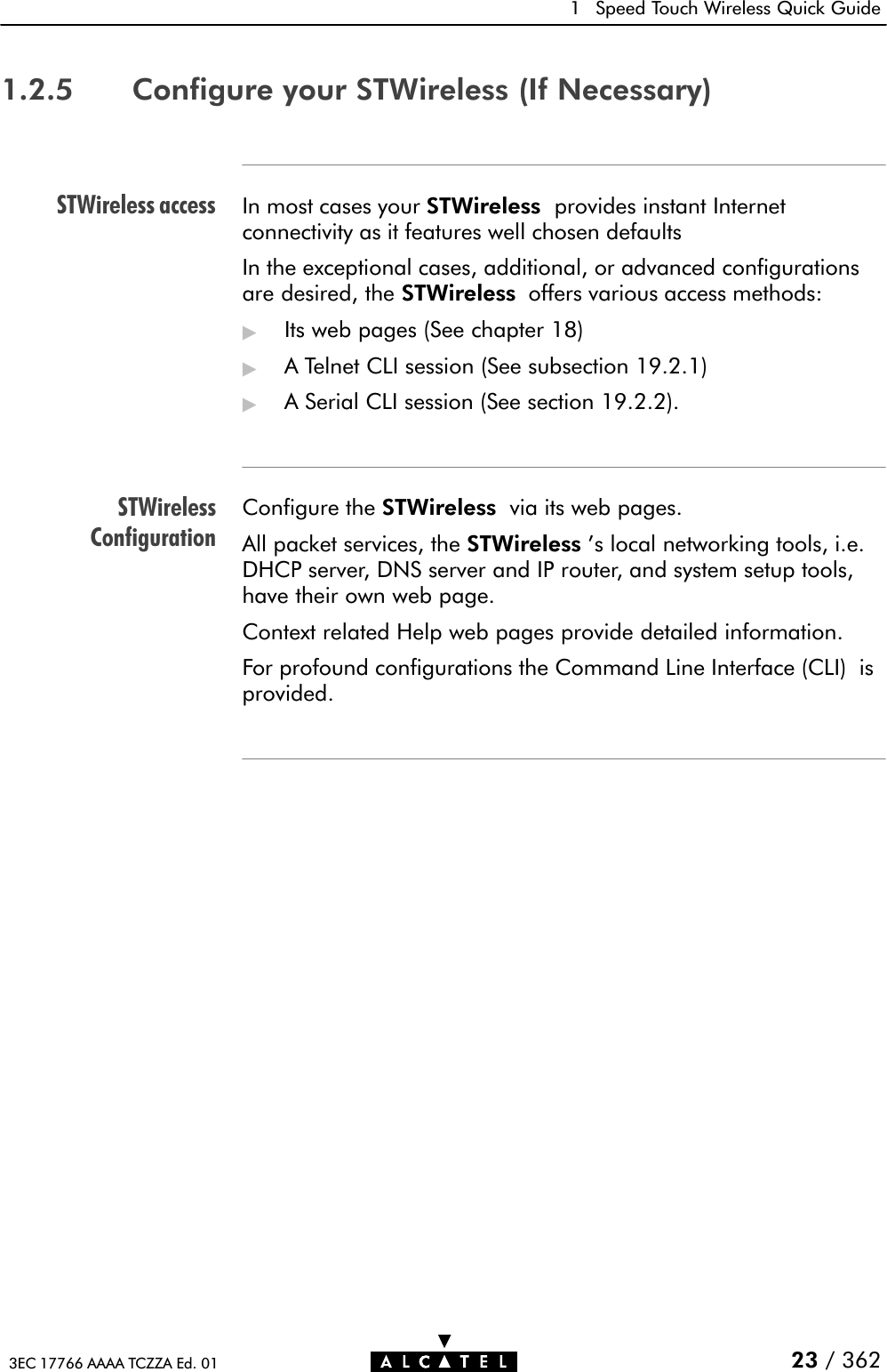
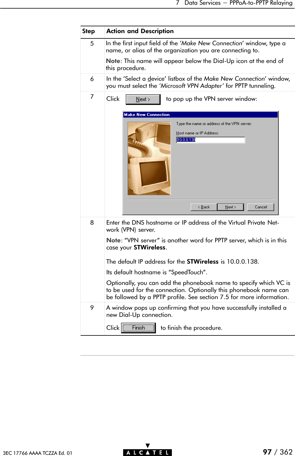
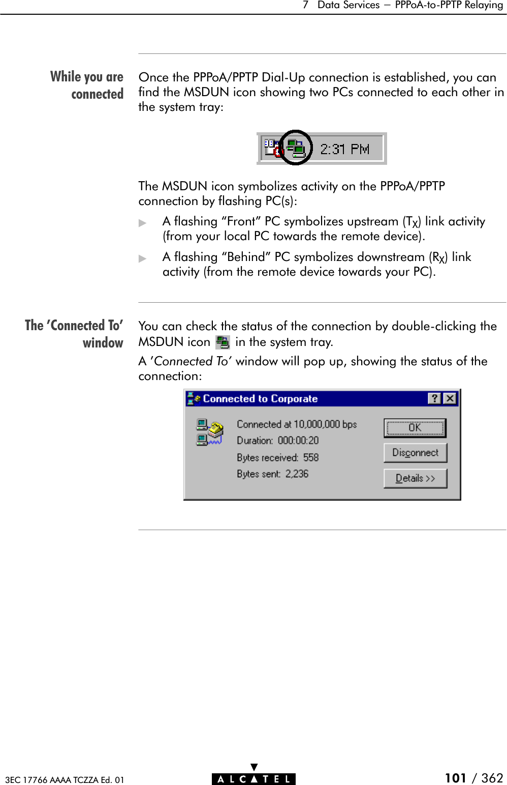
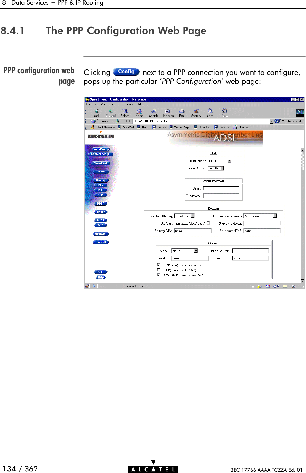
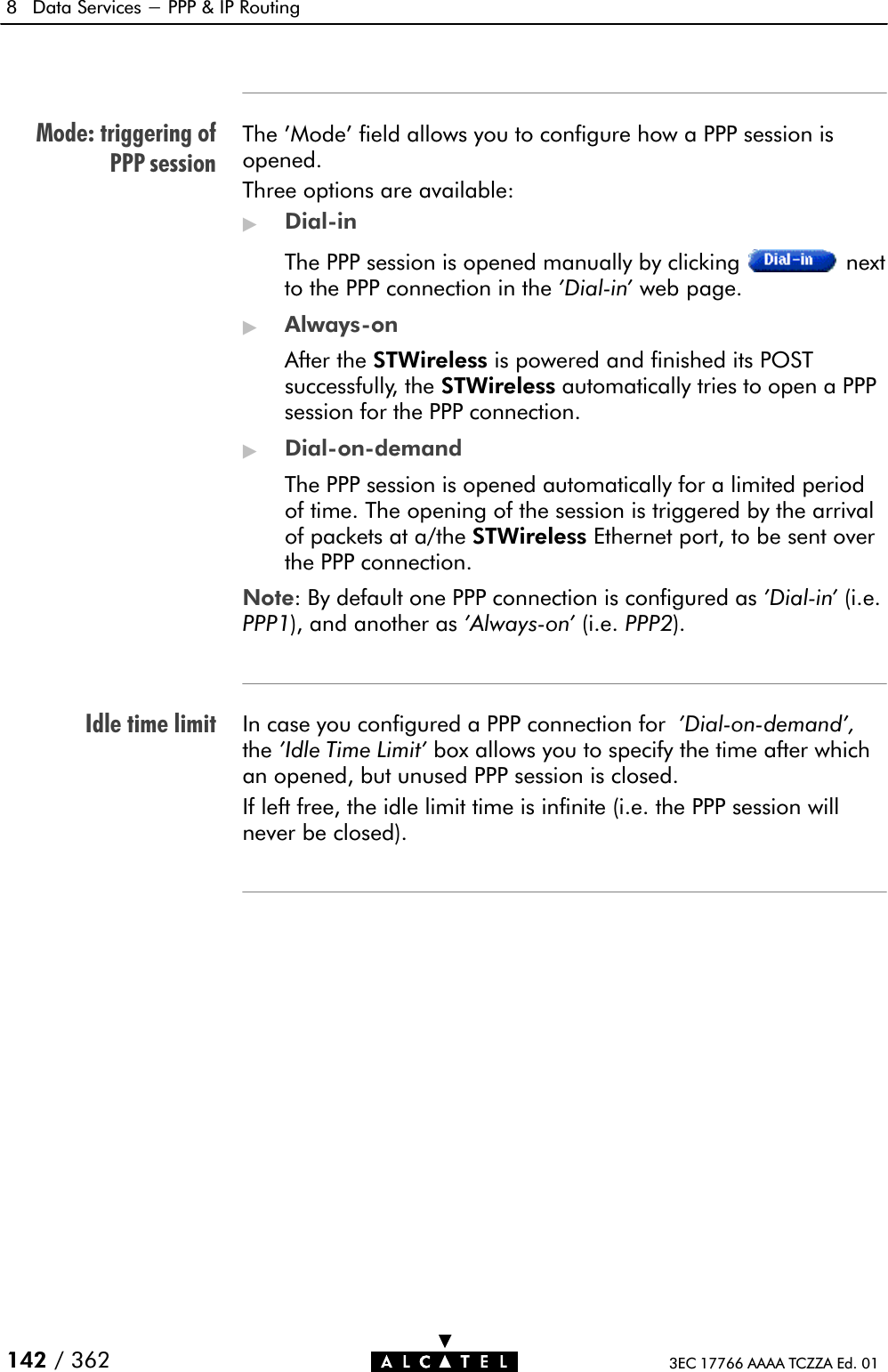
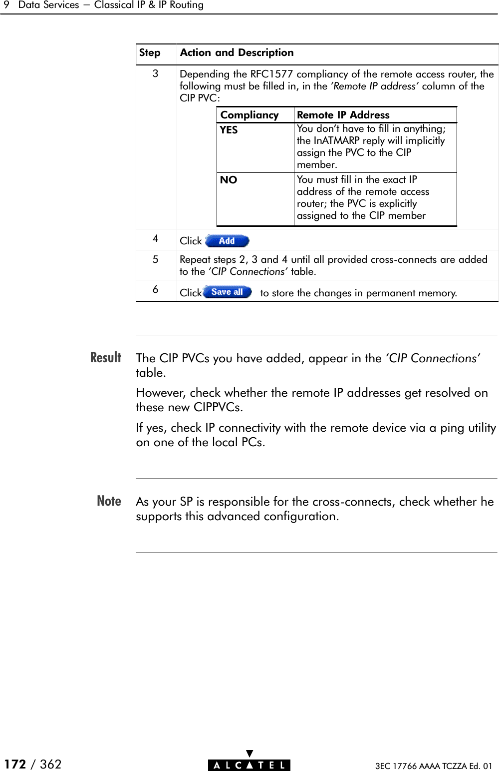
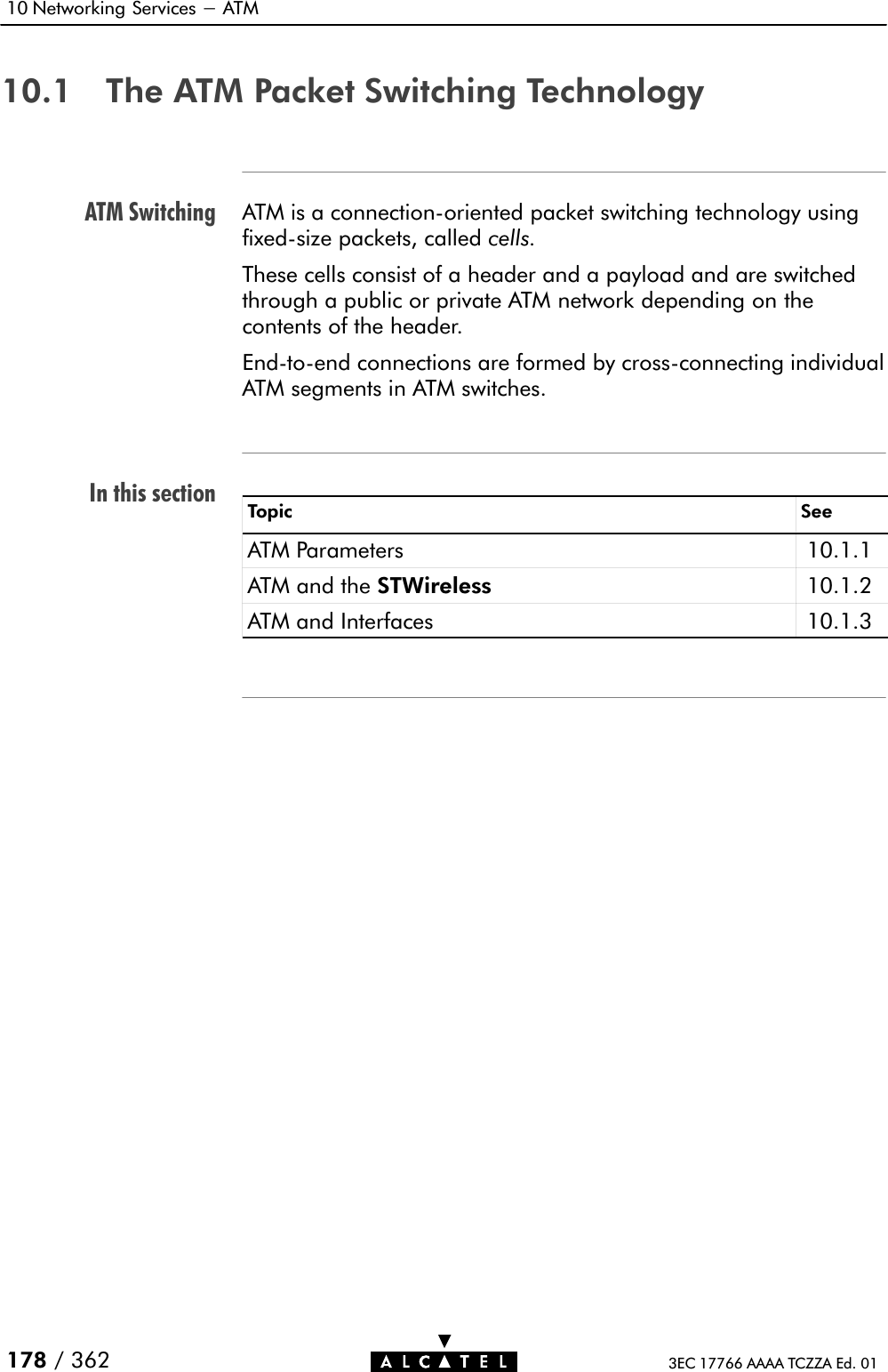
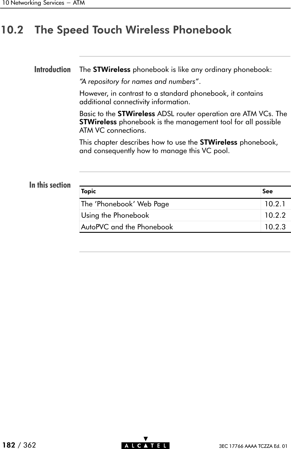
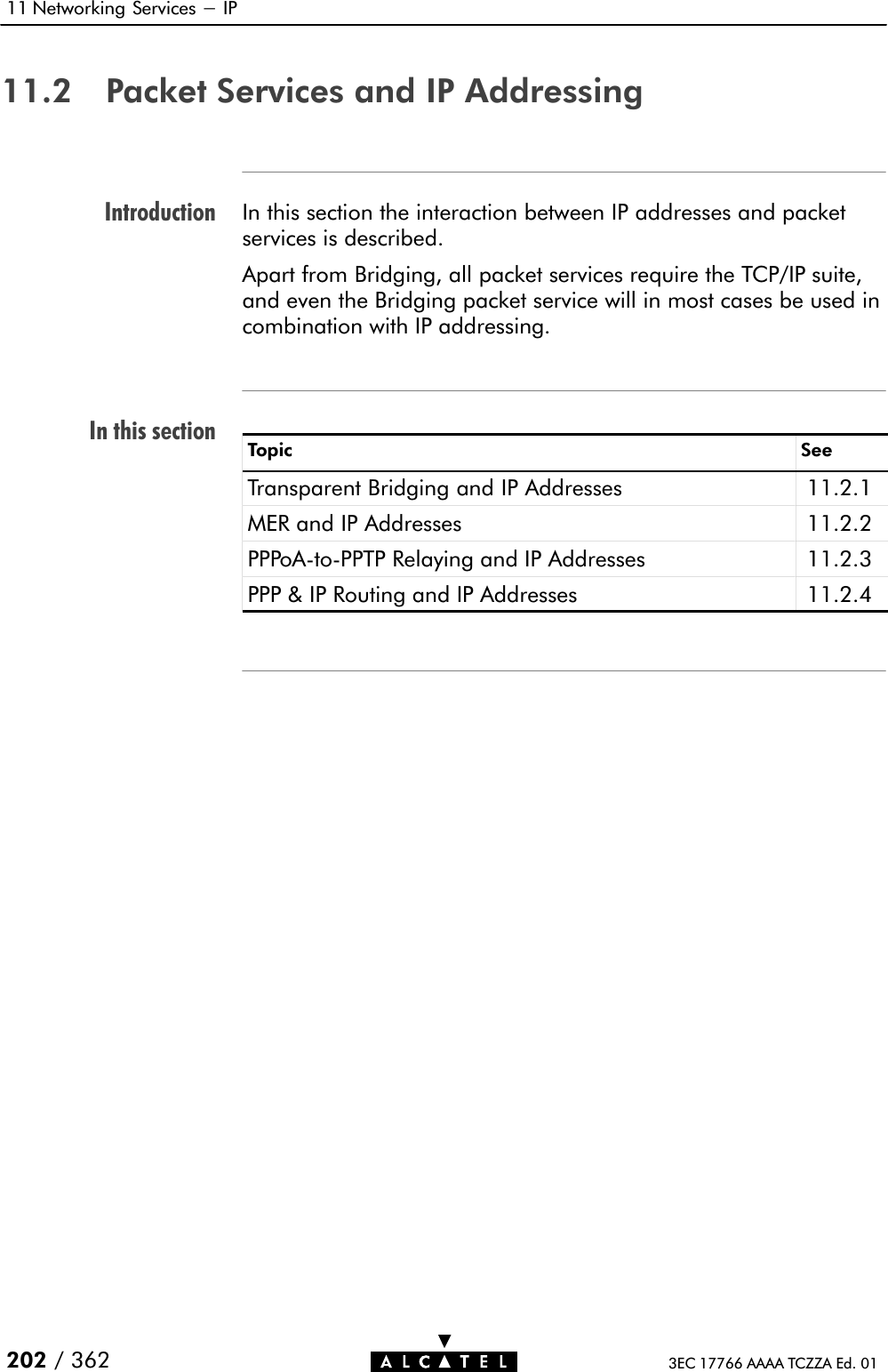
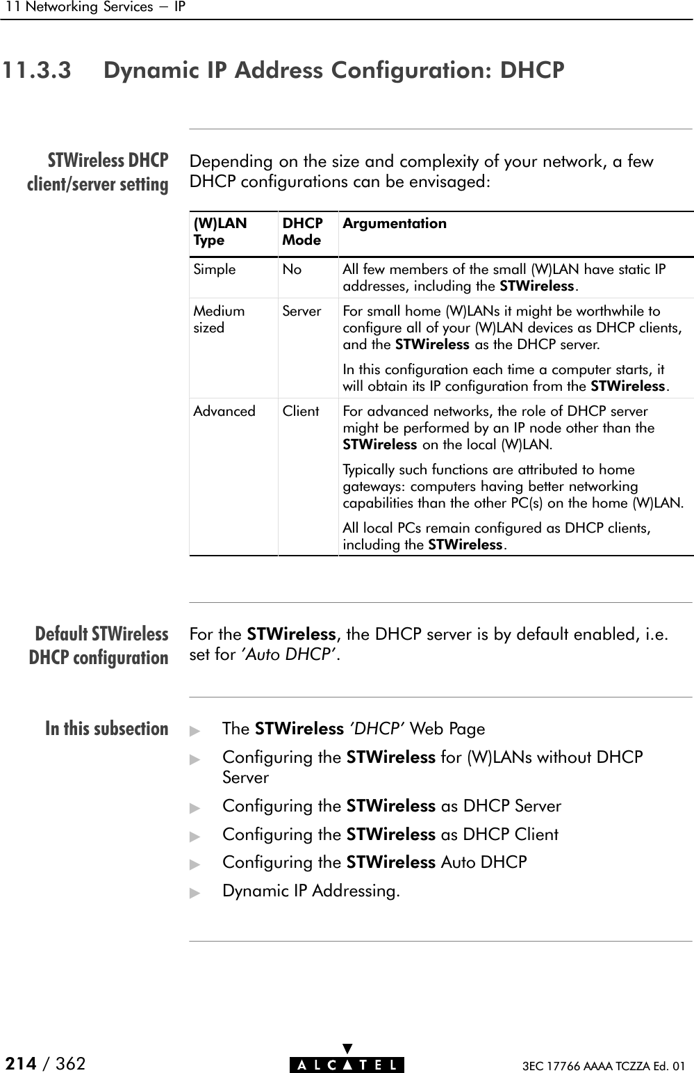
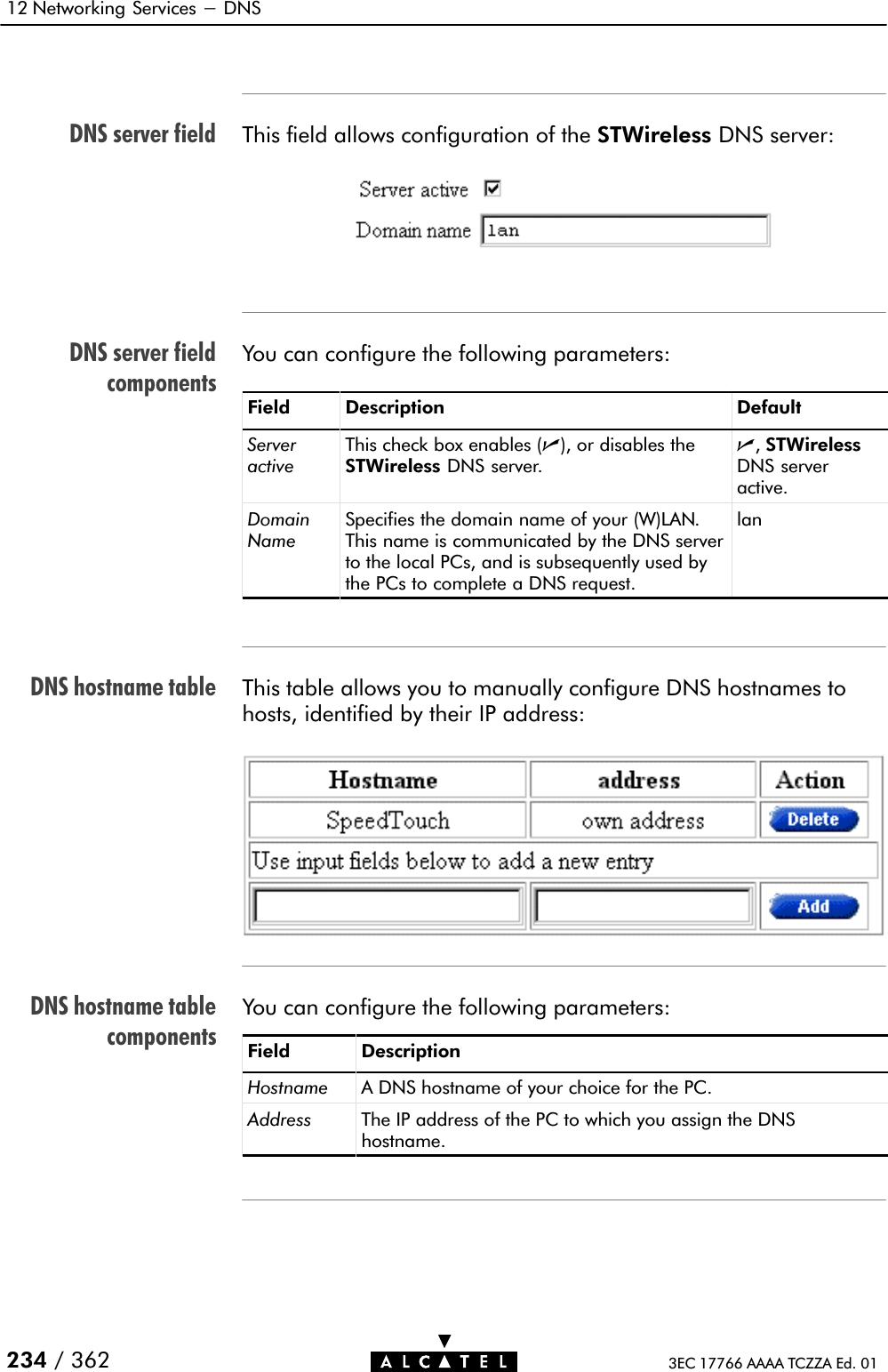
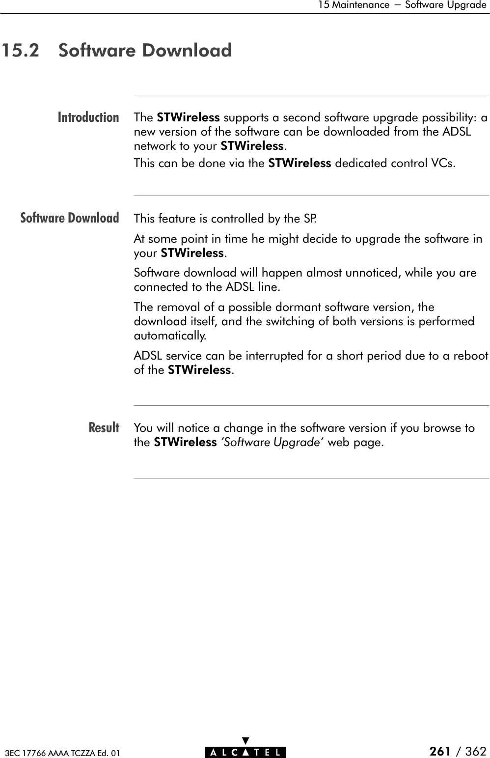
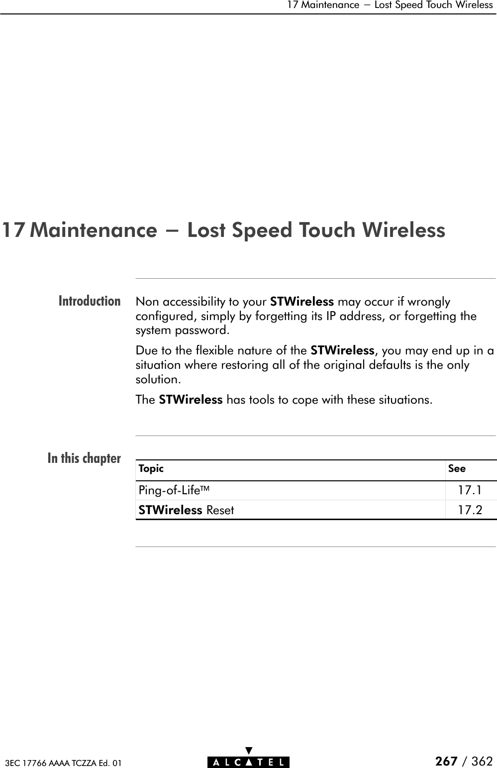
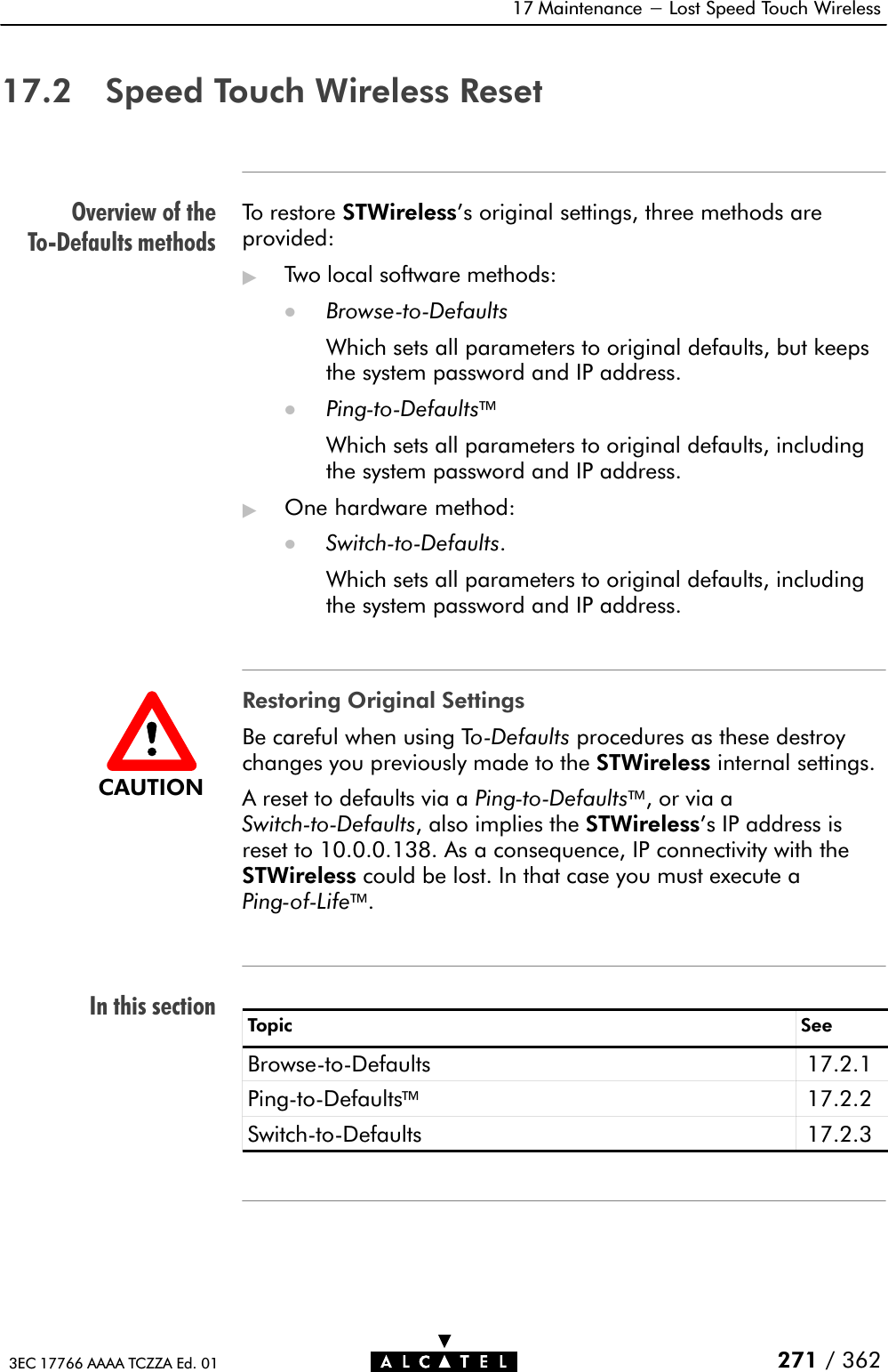
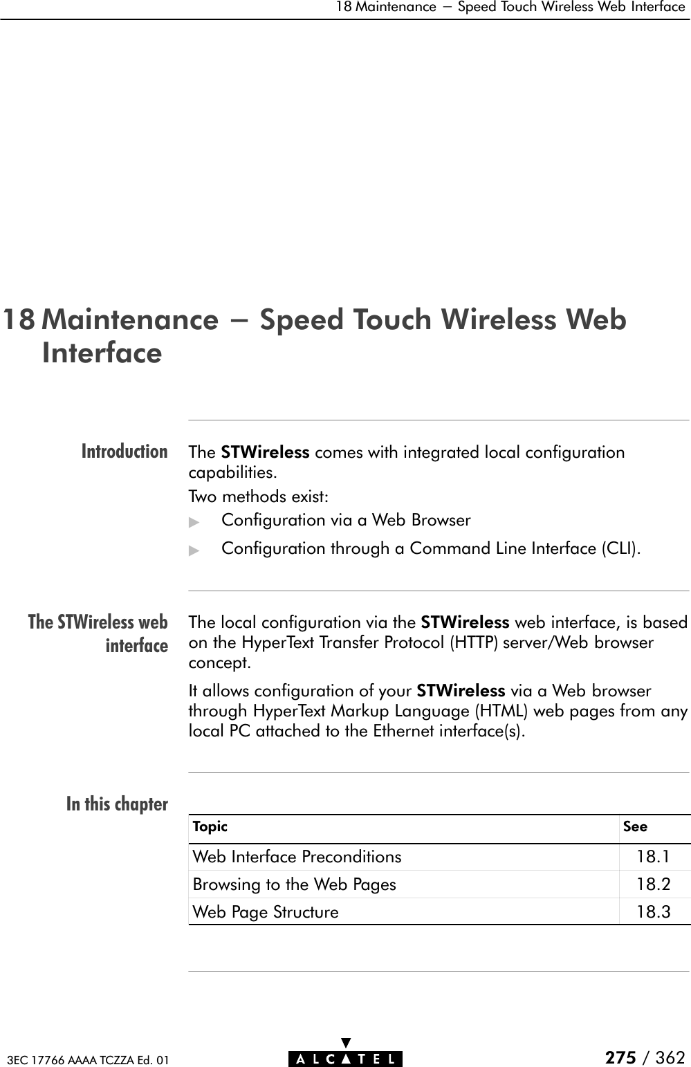
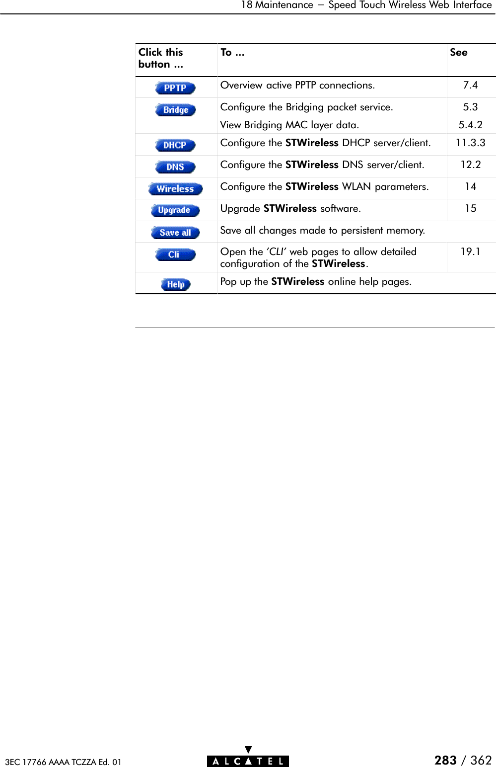
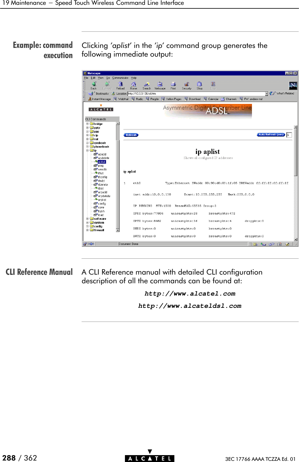
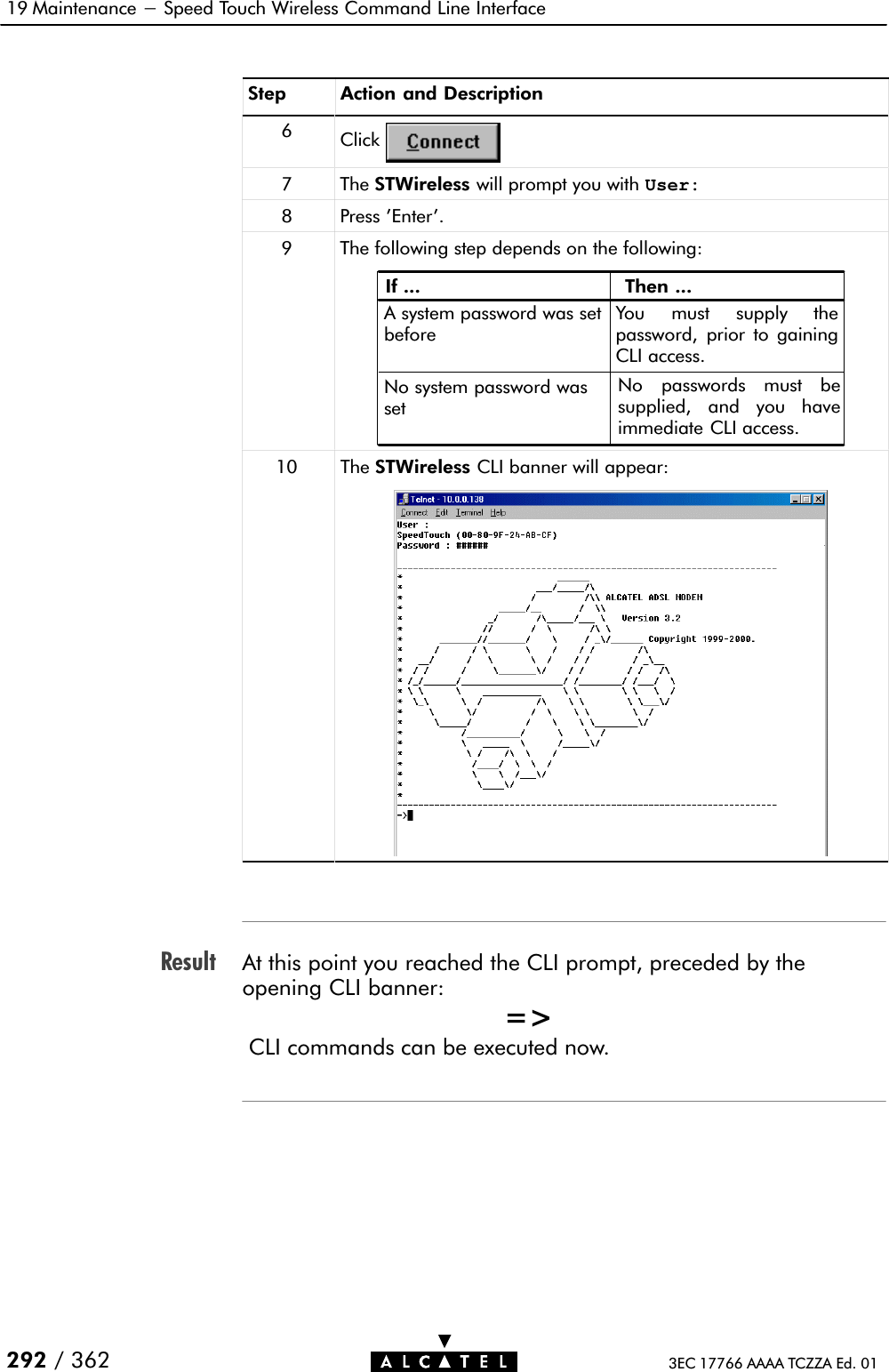
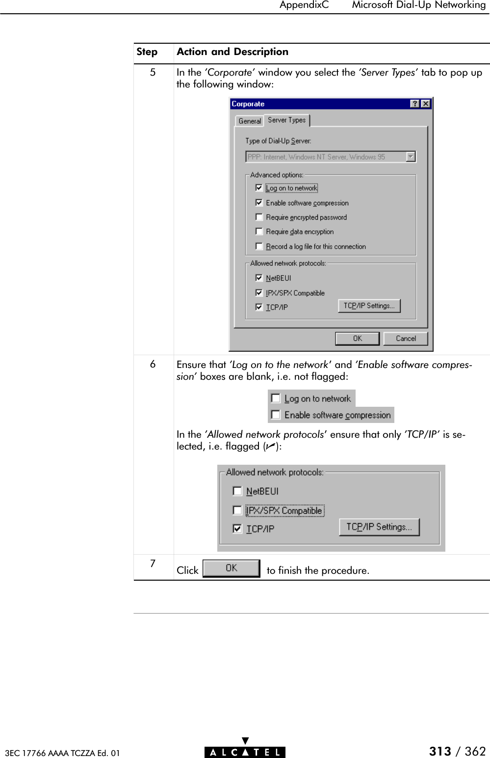
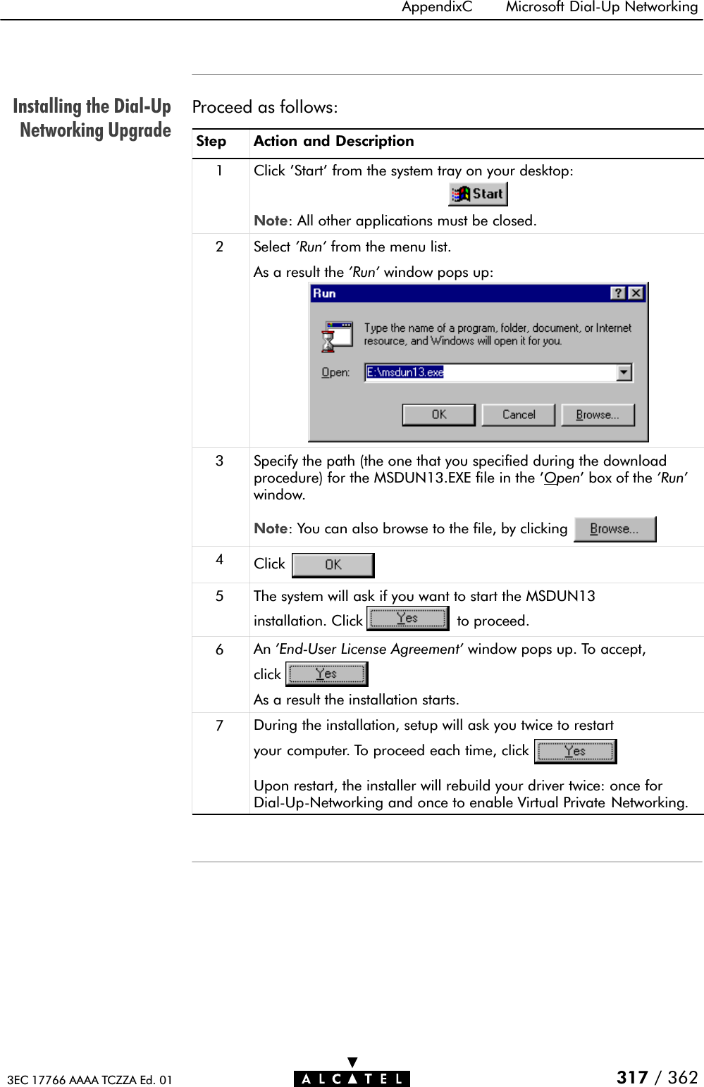
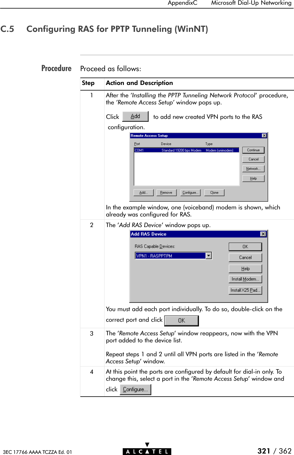
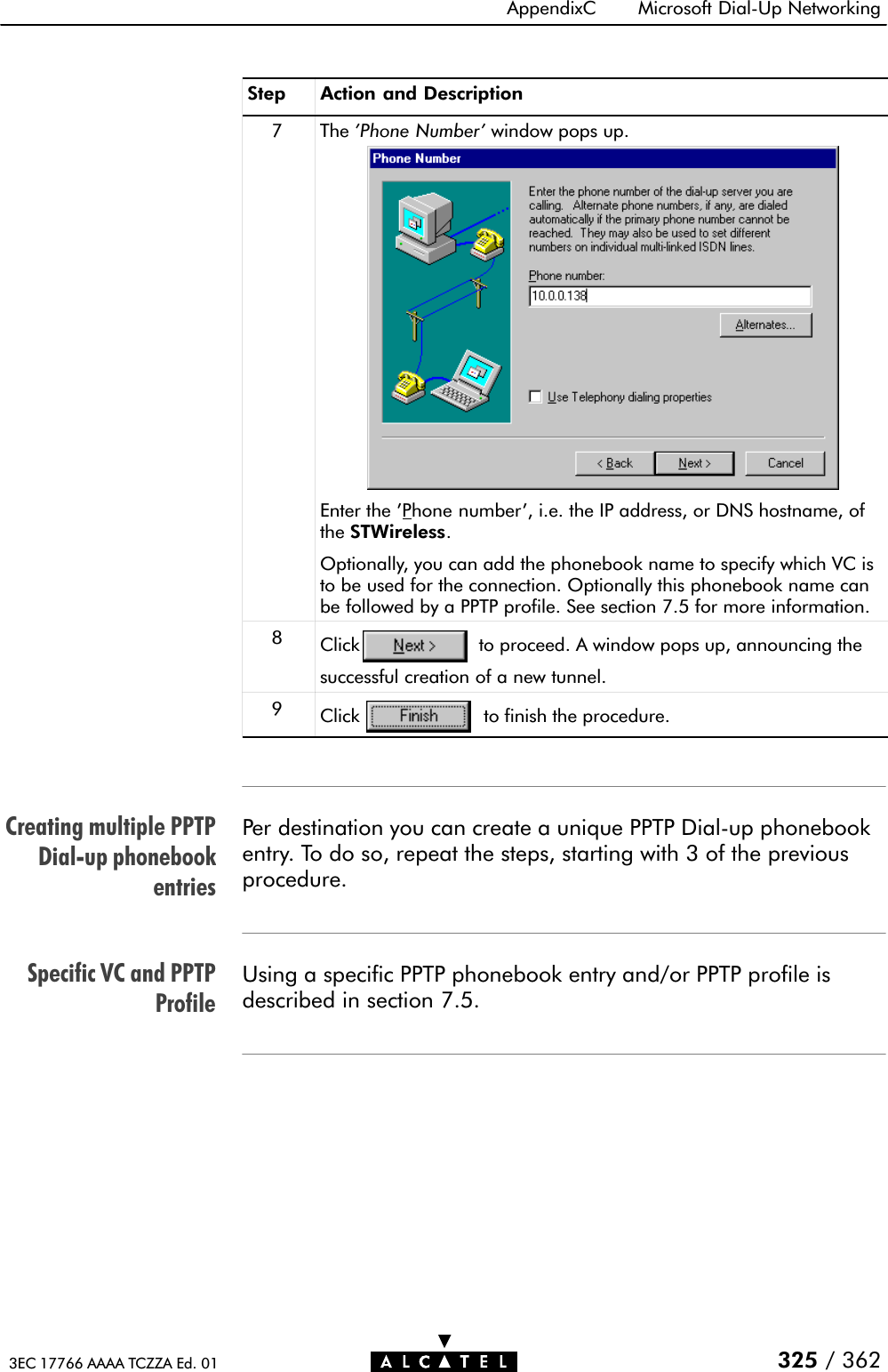
![Command group helpCommand helpCommand executionCLI Reference Manual19 Maintenance - Speed Touch Wireless Command Line Interface296 / 362 3EC 17766 AAAA TCZZA Ed. 01Typing help at the command group level prompt shows you theavailable commands.For example , entering help at the 'config' level generates thefollowing output:[config]=>helpFollowing command groups are available :save : Saves complete configuration.erase : Removes all saved data.load : Loads saved or factory default configuration.flush : Flushes complete configuration.reset : Flush & restore factory default configuration.[config]=>Typing help followed by a command generates shows you adescription of the command, and a parameter syntax, ifapplicable:For example , entering help reset in the 'config' levelgenerates the following output:[config]=>help reset [keep_ip = <{no|yes}>] Reset IP settings or not. Resetting IP can break current telnet/http session ![config]=>Typing the command executes the command. In most cases youmust also provide related parameters.The consequences of a command execution have immediateeffect. However, only after executing the save command, the newsettings are stored in persistent memory.A CLI Reference manual with detailed CLI configurationdescription of all the commands can be found at:http://www.alcatel.comhttp://www.alcateldsl.com](https://usermanual.wiki/Alcatel-USA/0101/User-Guide-159918-Page-296.png)


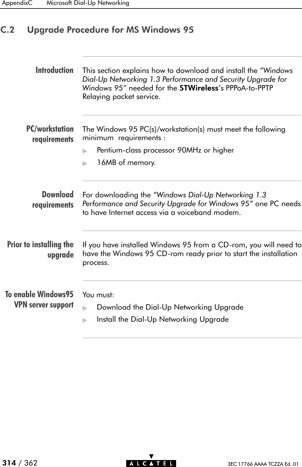
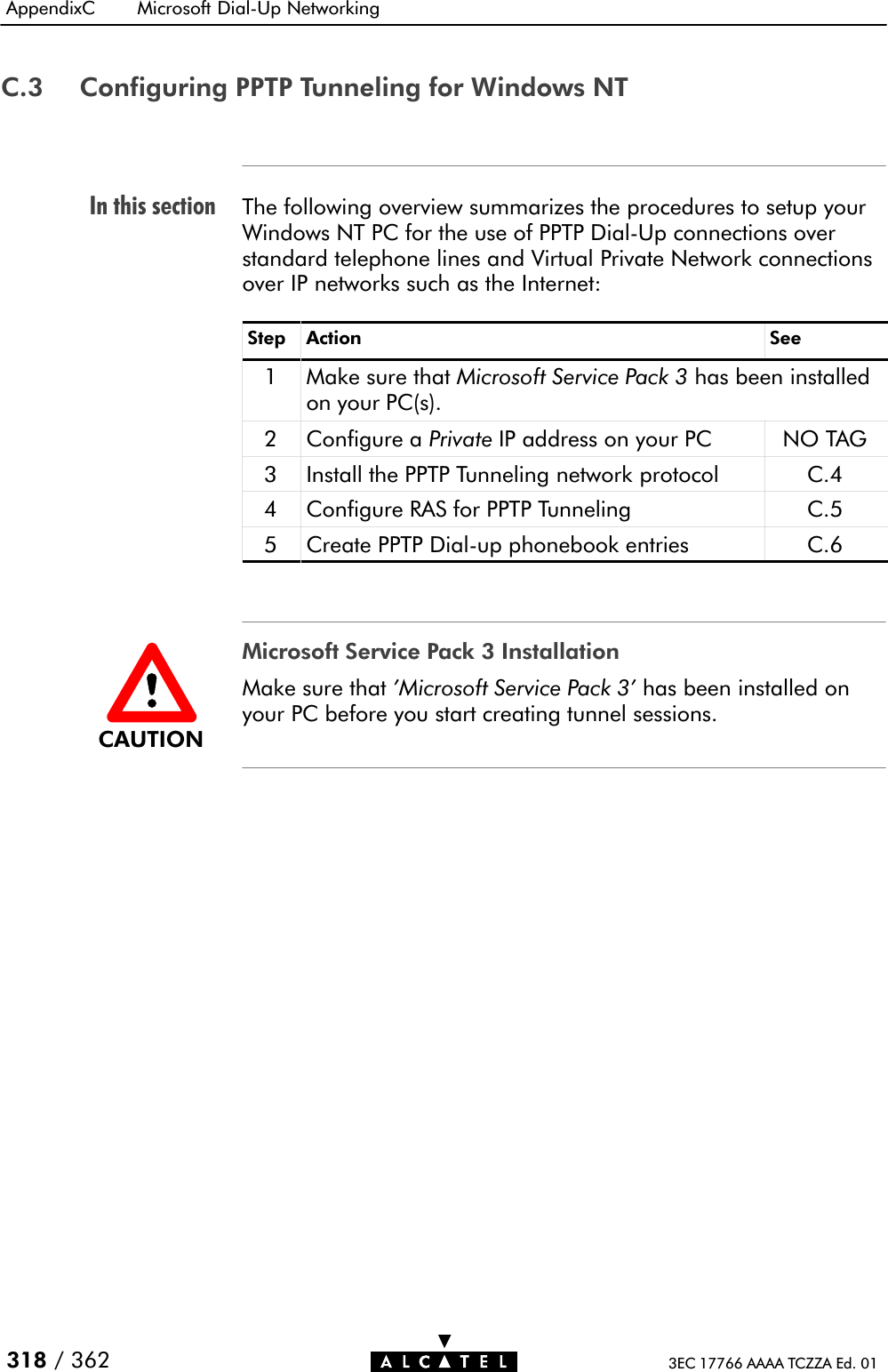
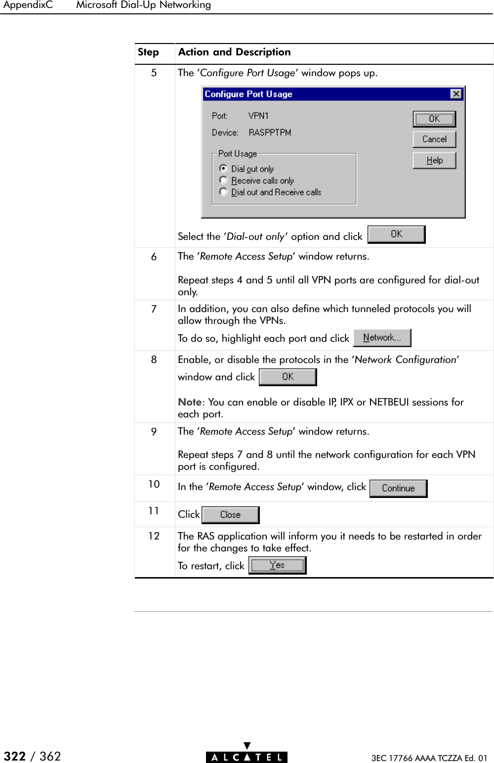
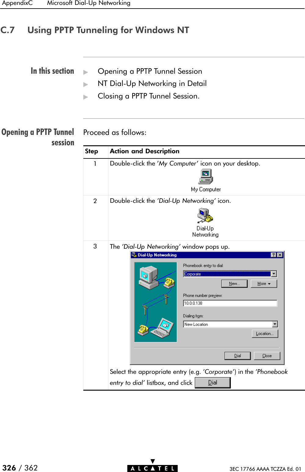
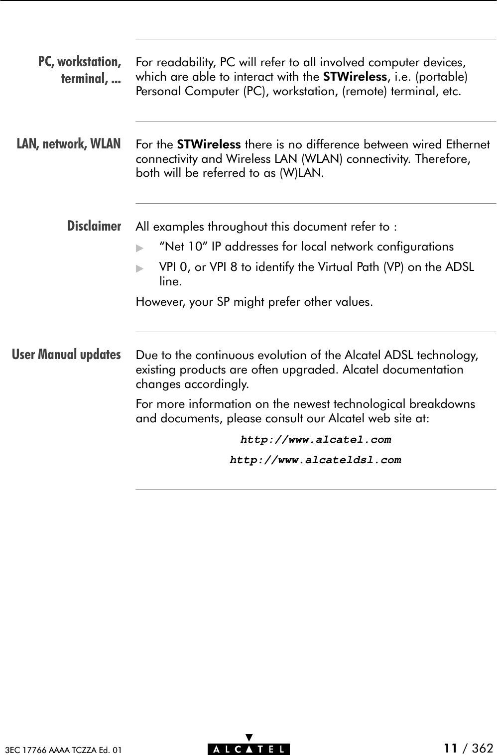
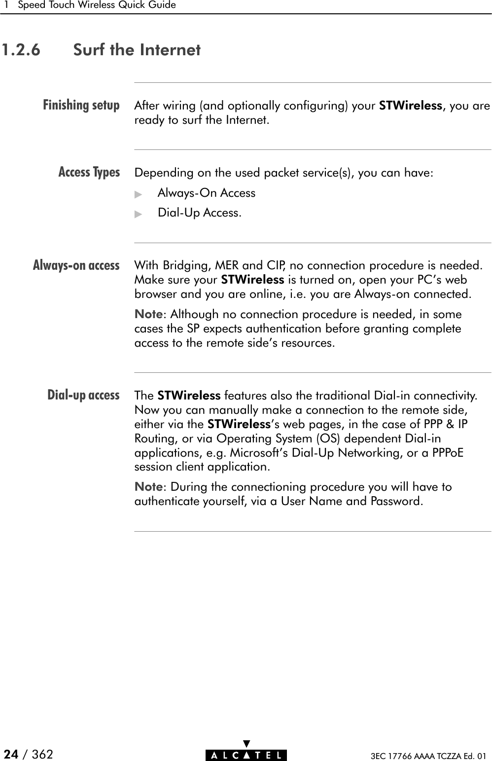
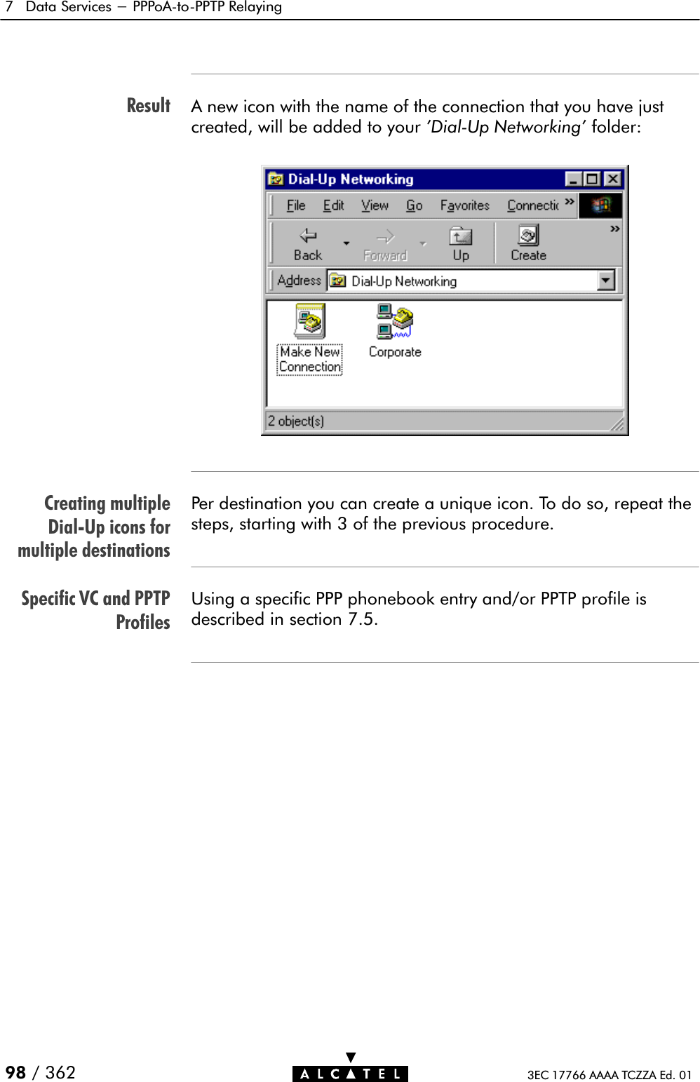
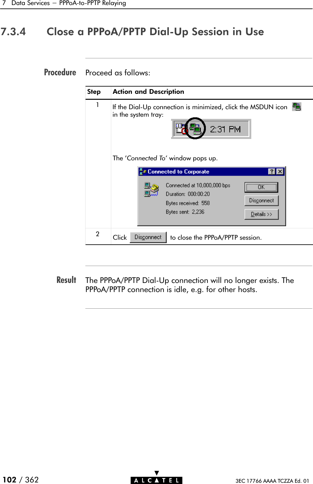
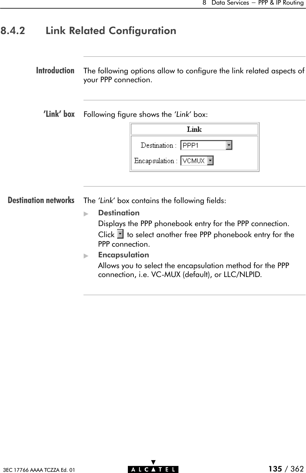
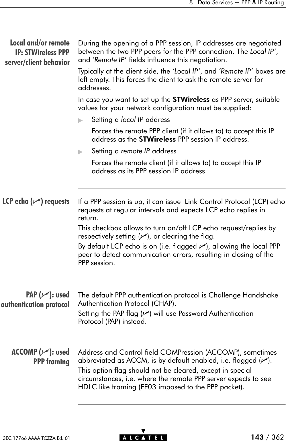
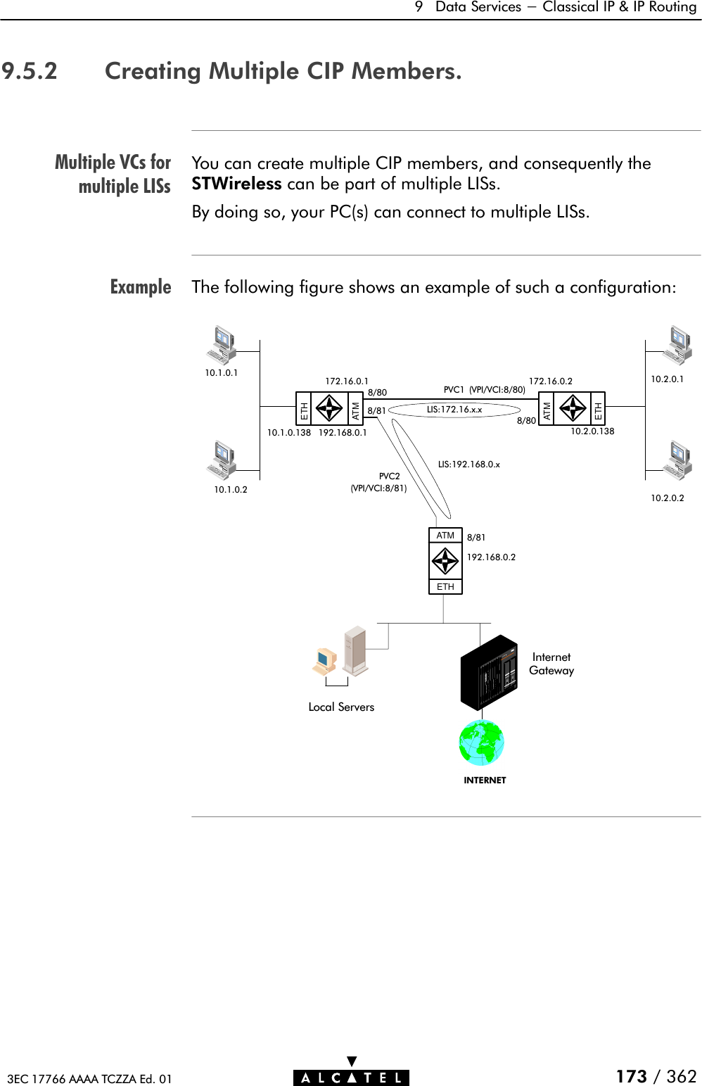
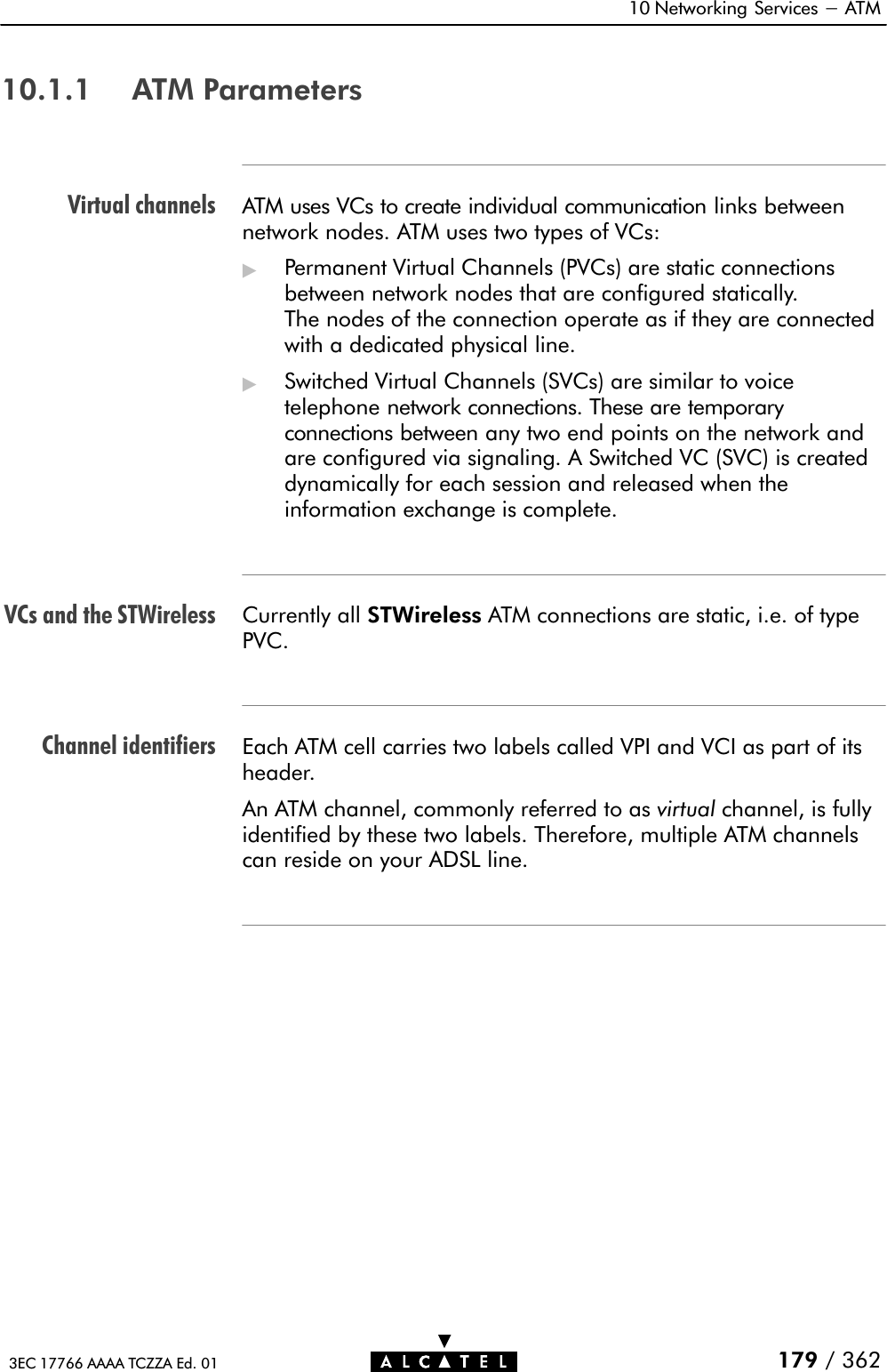
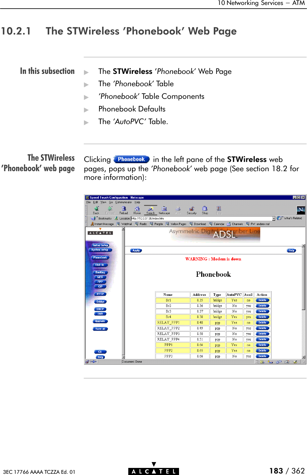
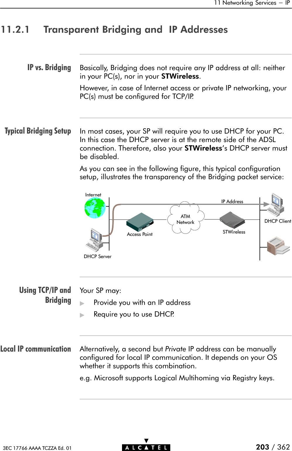
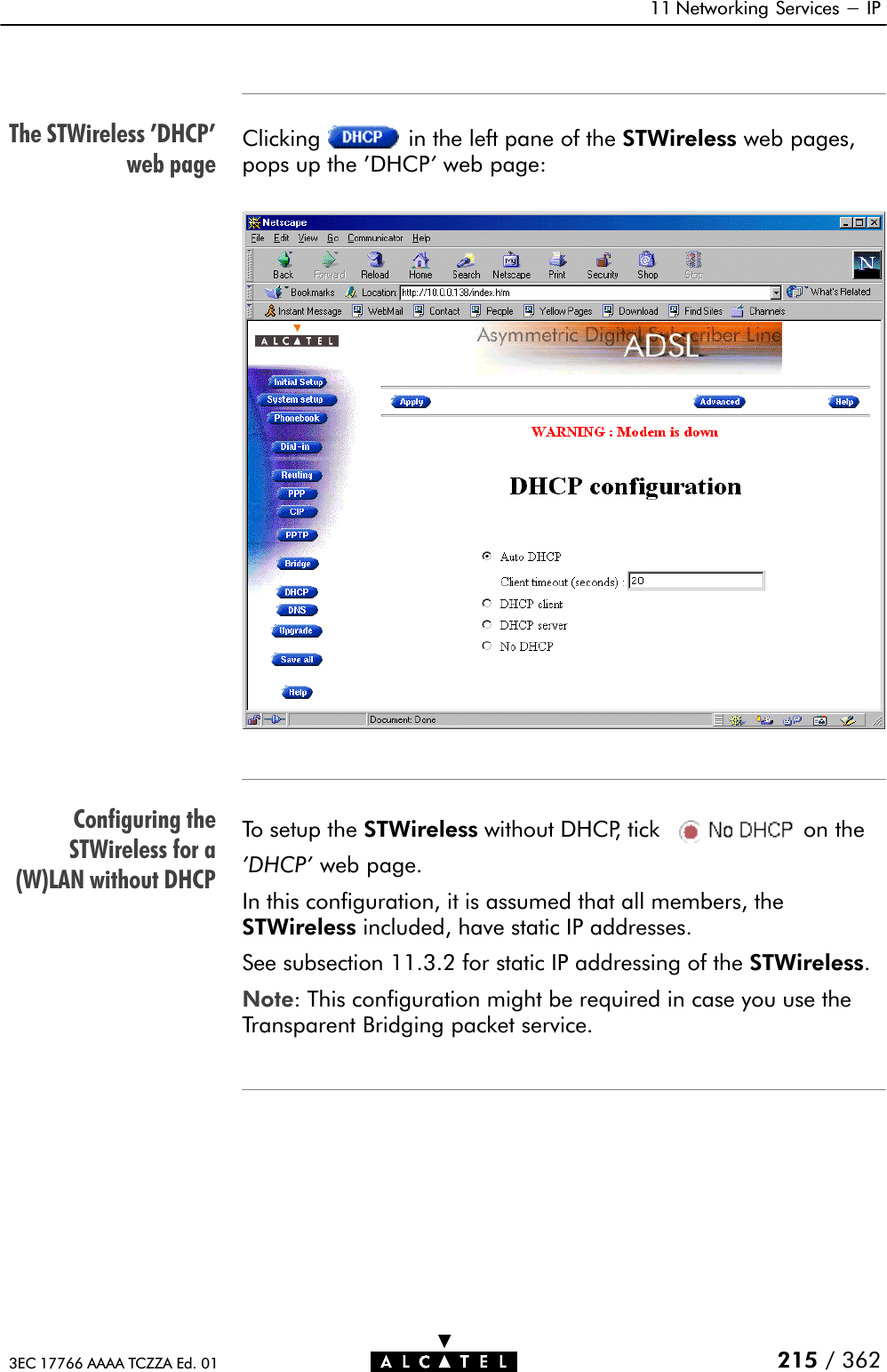
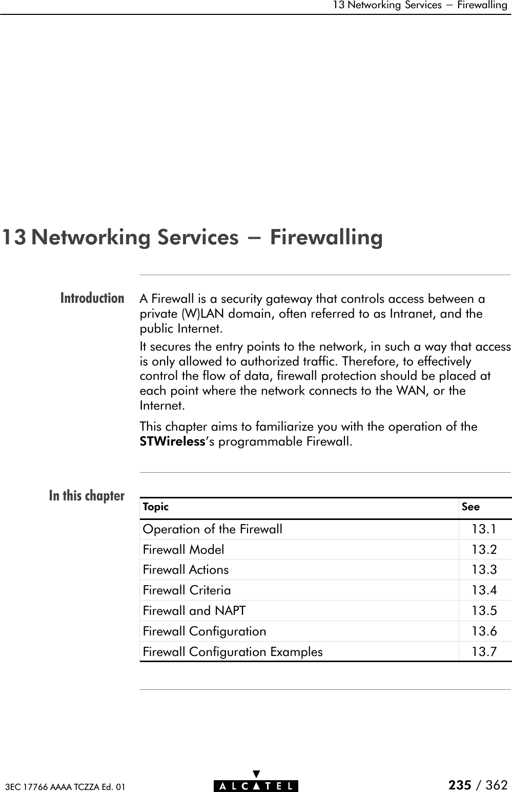
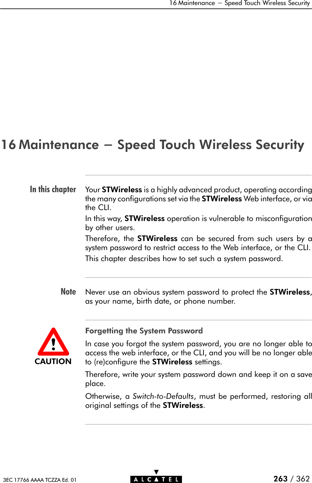
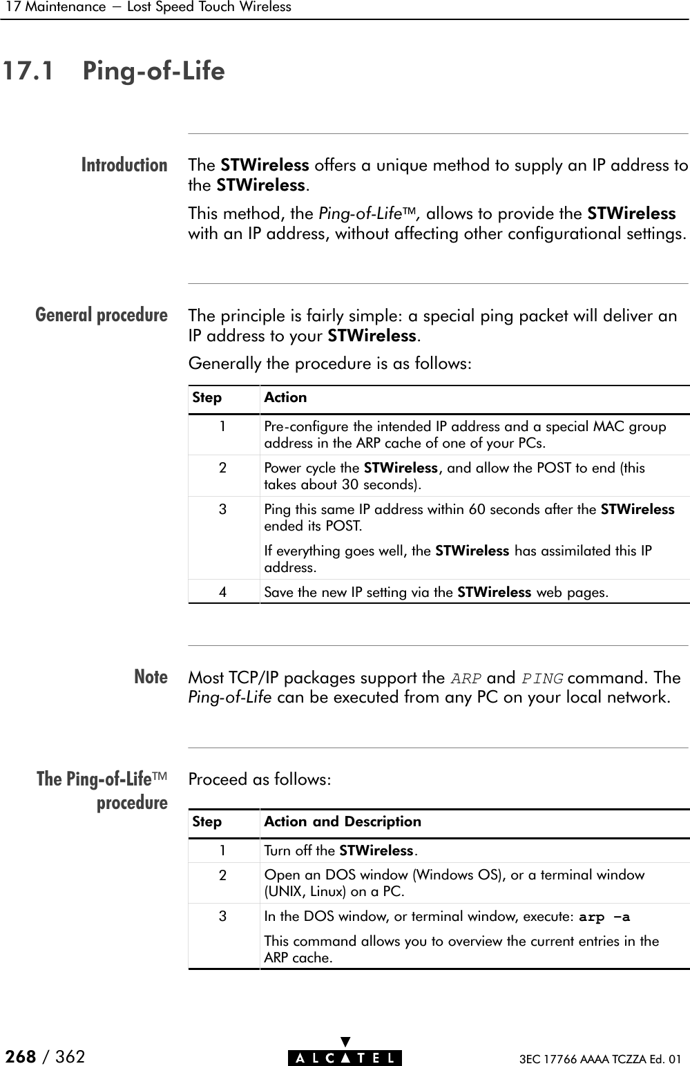
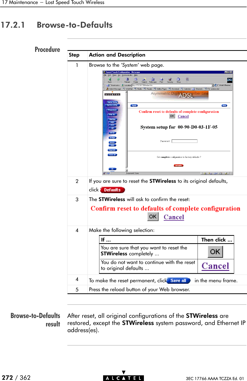
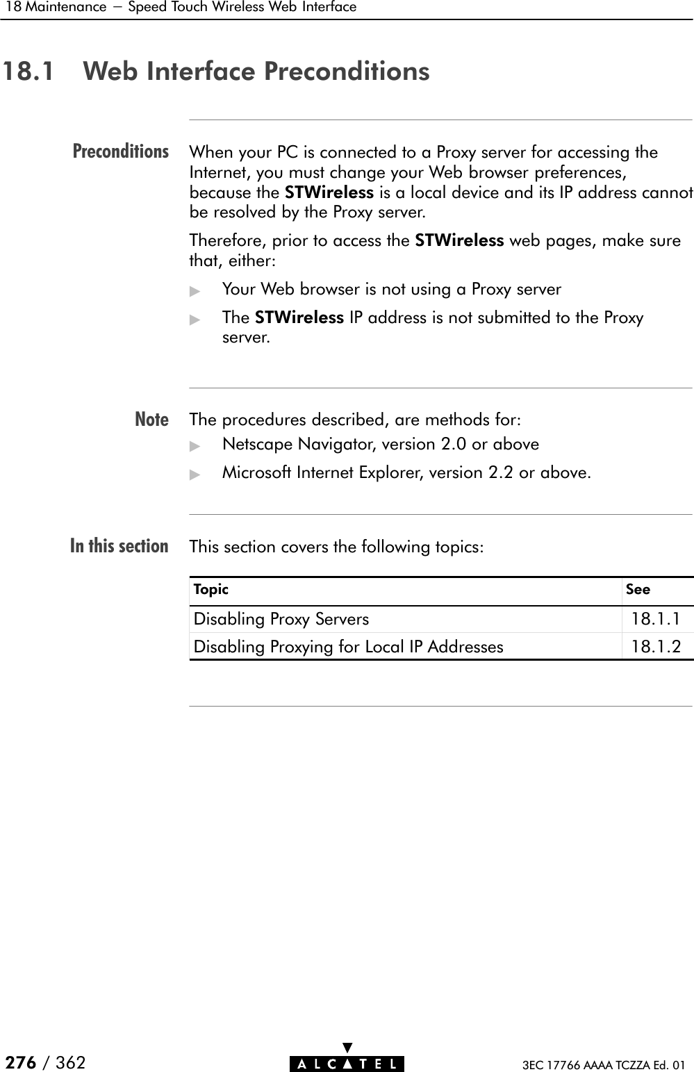
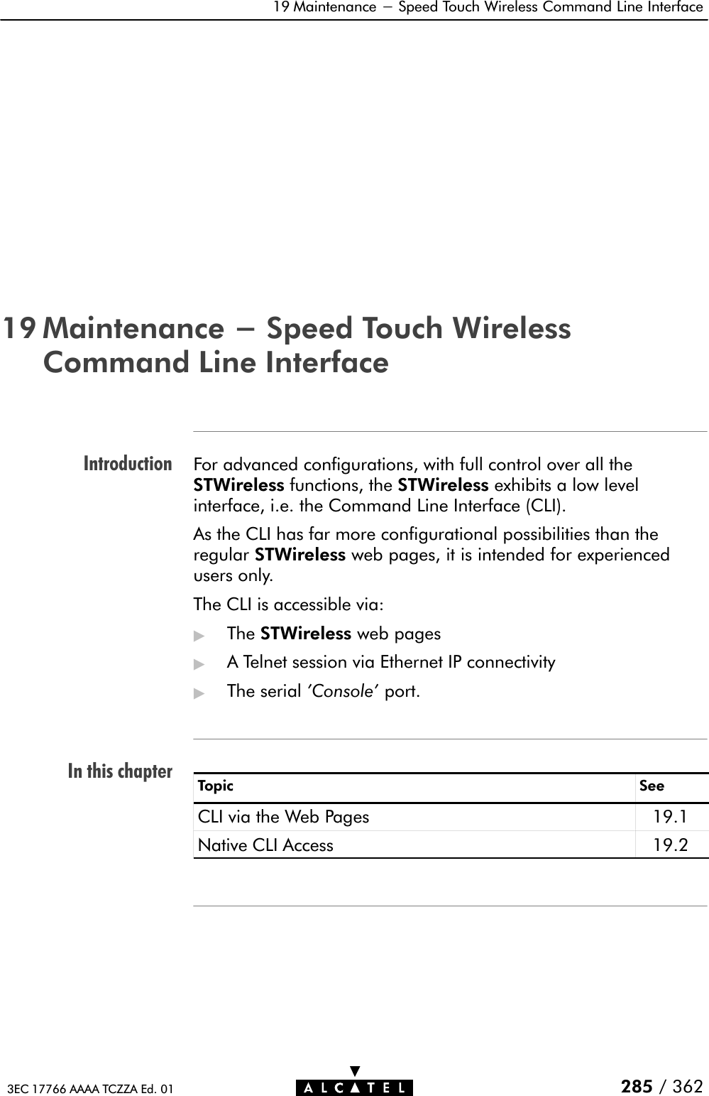
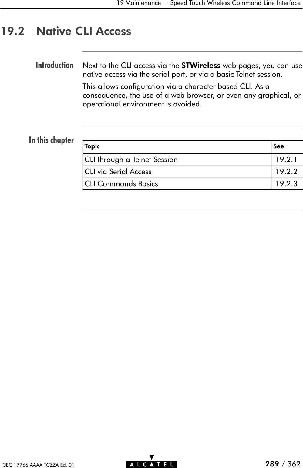
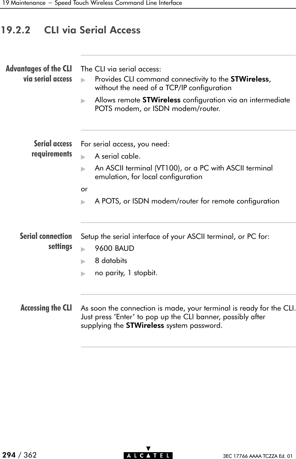
![STWireless portdescriptionFree connector pinsAppendixF Hardware Reference348 / 362 3EC 17766 AAAA TCZZA Ed. 01F.2 Connector Pin AssignmentsPort PinNo.SignalNameFunction ModelReference1234562 Wire A Subscriber linewire A2/5 model123456RJ 11/RJ 14E3 Wire A Subscriber linewire A3/4 modelFront viewLINE4 Wire B Subscriber linewire B5 Wire B Subscriber linewire B2/5 model12345678 1 RX+ Receive data from DTE* (+)RJ 45 2 RX- Receive data from DTE* (-)RJ 45Front view 3 TX+ Transmit data to DTE* (+)Front view6 TX- Transmit data to DTE* (-)Inner +9VDC Power supply connection (+)Outer GND Power supply connection(ground)123452 RD[RS232Ć9]Received data123453 SD[RS232Ć9]Transmitted data6789 5 DCD[RS232Ć9]Signal commonNote: (*) Data Terminal Equipment (DTE)Connector pins not mentioned are not connected.](https://usermanual.wiki/Alcatel-USA/0101/User-Guide-159918-Page-348.png)