Alcatel Canada 39T28A03A22A Alcatel 7390 LMDS Multiservice Broadband Wireless User Manual 3cc12426aaaaTQbja01
Alcatel Canada Inc Alcatel 7390 LMDS Multiservice Broadband Wireless 3cc12426aaaaTQbja01
Contents
- 1. Base Station User Manual 1 of 14
- 2. Base Station User Manual 2 of 14
- 3. Base Station User Manual 3 of 14
- 4. Base Station User Manual 4 of 14
- 5. Base Station User Manual 5 of 14
- 6. Base Station User Manual 6 of 14
- 7. Base Station User Manual 7 of 14
- 8. Base Station User Manual 8 of 14
- 9. Base Station User Manual 9 of 14
- 10. Base Station User Manual 10 of 14
- 11. Base Sation User Manual 11 of 14
- 12. Base Sation User Manual 12 of 14
- 13. Base Sation User Manual 13 of 14
- 14. Base Sation User Manual 14 of 14
Base Station User Manual 2 of 14
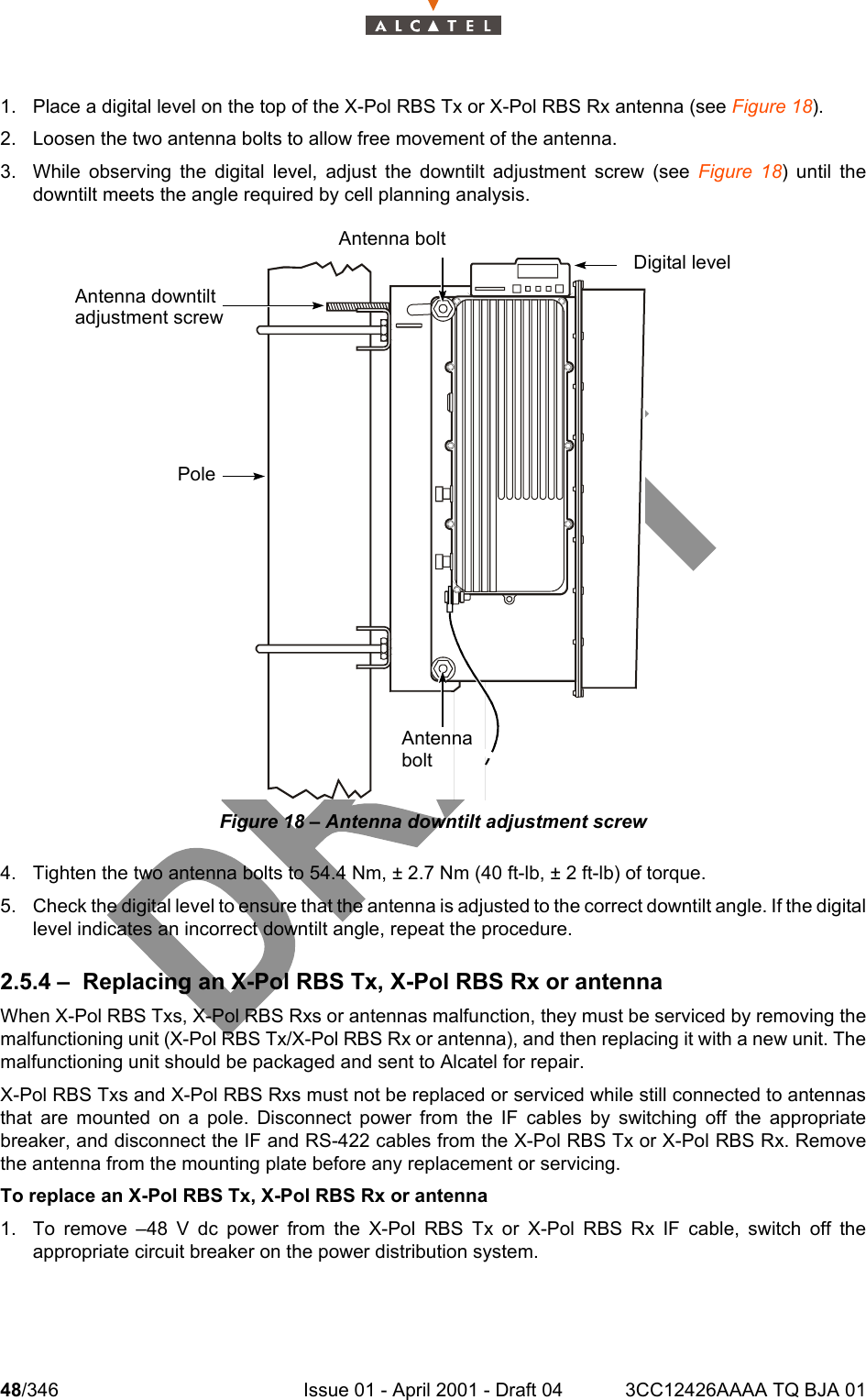
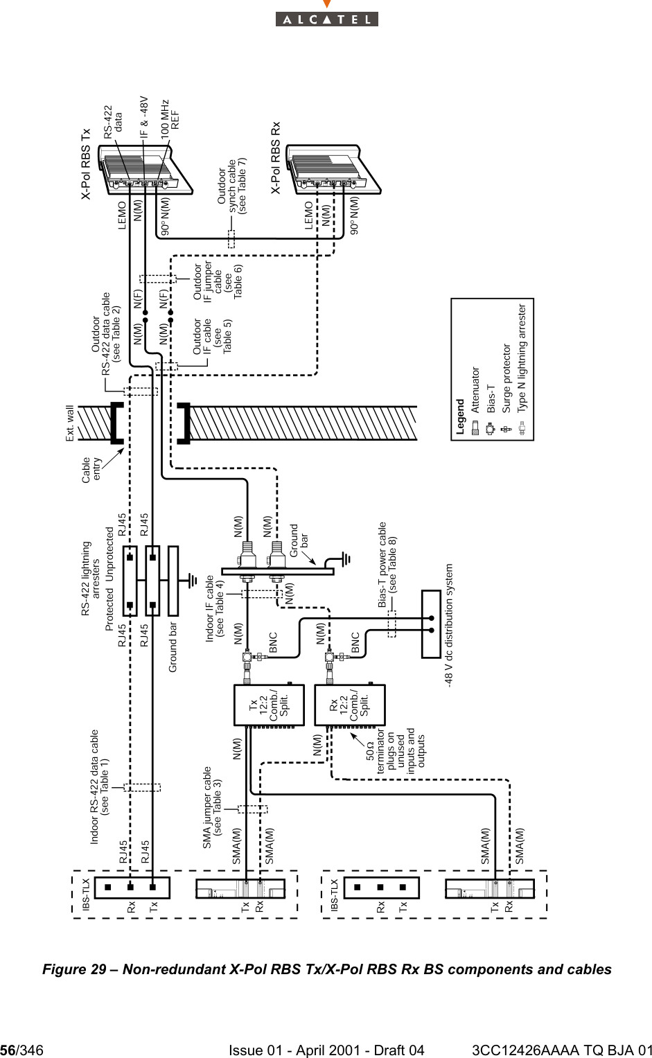
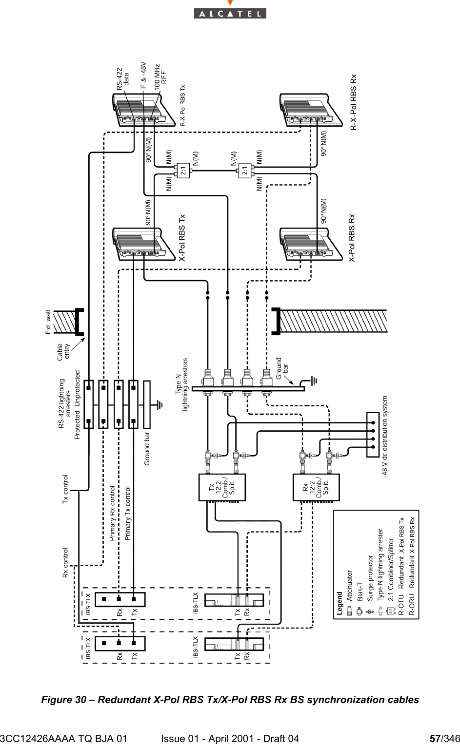
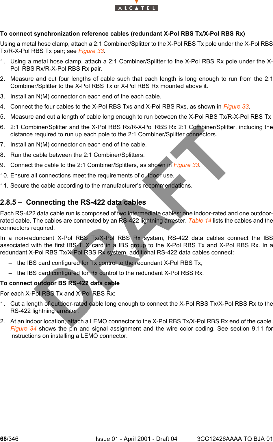
![58/346 Issue 01 - April 2001 - Draft 04 3CC12426AAAA TQ BJA 01104Table 14: RS-422 data cables and connectorsNote: Alcatel part number 90-6815-01 (Stewart RJ45 connector)LEMO USA part number FGG.1K.304.CLCC.60Z (connector strain relief part numberGMA.1B.065.DN)Table 15: SMA jumper cable and connectorsTable 16: IF cables and connectorsTable 17: Synchronization cable and connectorsTable 18: Bias-T power supply cable and connectorsCable rating Description Connectors Recommended cablesIndoor IBS-TLX connector to RS-422 lightning arrester RJ45(1) - RJ45(1) Delco 398087POutdoor RS-422 lightning arrester to X-Pol RBS Tx/X-Pol RBS Rx RJ45(1) - LEMO(2) Delco 398087Cable rating Description Connectors Recommended cablesIndoor IBS-TLX card toTx 12:2 Combiner/SplitterIBS-TLX card toRx 12:2 Combiner/SplitterSMA(M) - SMA(M) 90-6656-01 (3 m [10 ft])90-6656-02 (6 m [20 ft])Cable rating Description Connectors Recommended cablesIndoor Bias-T to Type N lightning arres-ter N(M) - N(M) See Table 20Outdoor (main)Type N lightning arrester to IF jumper cable N(M) - N(M) See Table 20Outdoor (jumper)IF jumper cable (1 m [3 ft]) to X-Pol RBS Tx/X-Pol RBS Rx N(F) - N(M)Times Microwave LMR-400 (part number FT-400DB/3/NM/NF)Cable rating Description Connectors Recommended cablesOutdoor X-Pol RBS Tx to X-Pol RBS Rx 100 MHz REF connector See Table 23 LDF2-50Cable rating Description Connectors Recommended cablesIndoor Surge protector to –48 V dc dis-tribution system BNC(F) - ring lugs 90-6518-01](https://usermanual.wiki/Alcatel-Canada/39T28A03A22A.Base-Station-User-Manual-2-of-14/User-Guide-175935-Page-18.png)
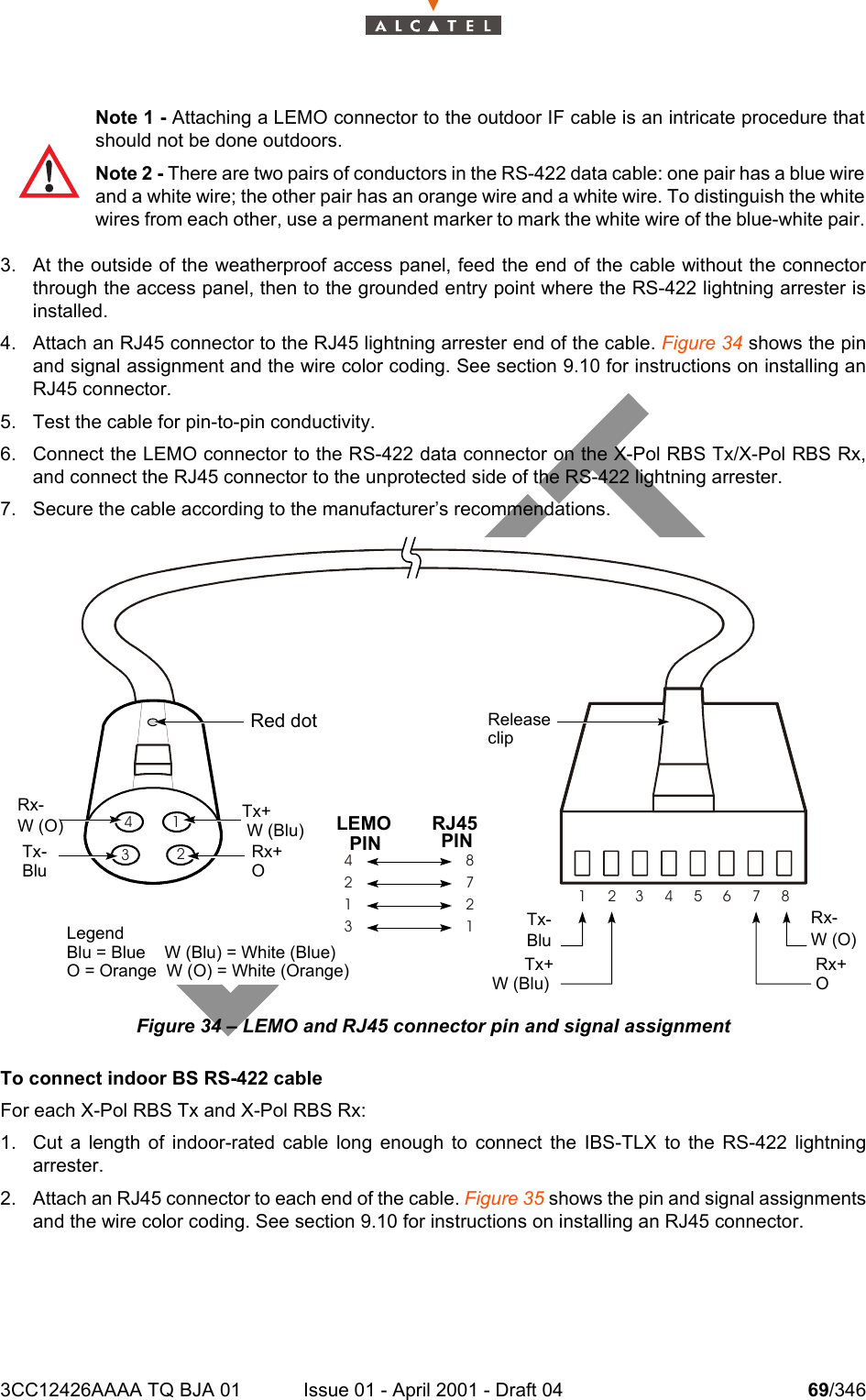
![3CC12426AAAA TQ BJA 01 Issue 01 - April 2001 - Draft 04 59/3461042.8.1 – Selecting BS IF cablesWhen selecting BS IF cables, the main concern is the IF cable signal loss of the indoor and outdoor cableruns.The system requires that all the components in the IF signal path between the IBS card and the X-PolRBS Tx/X-Pol RBS Rx (cables, connectors and equipment) provide a fixed decibel loss in each of thedownstream and upstream directions. System performance may be affected if the fixed loss is not met.The downstream losses must total 27 dB ±1 dB at the upper frequency of the IF band used for thedownstream signal. The upstream losses must total 24 dB ±1 dB at the upper frequency of the IF bandused for the upstream signal.Table 19 can be used to determine how much loss the IF cables must contribute in order to achieve thefixed loss requirement. The table lists each component and gives its loss value at 2050 MHz downstreamand 900 MHz upstream. It is assumed that the installation uses a 3 m (10 ft) long SMA cable. The lastrow in the table shows that the IF cables, including connectors, must contribute the following losses tothe system at the frequencies used in this example:– 7.37 dB in the downstream path at 2050 MHz,– 4.37 dB in the upstream path at 900 MHz.Use the following formulas along with the cable and connector loss values given in Table 20 to determinethe types and lengths of cable that meet the fixed loss requirements and that are suitable for theinstallation. Formula 2 accounts for four connectors (two connectors for each of the indoor- and outdoor-rated cables). Formula 1: Calculation of dB loss for a cable segmentLosssegment = Lengthsegment X (dB loss/distancesegment ¸ 100)where Losssegment is the loss of the indoor or outdoor segment (in dB)Lengthsegment is the length of the segment (in m [ft])dB loss/distance is the loss characteristic of the segment (dB/100 m [dB/100 ft])Formula 2: Calculation of total dB loss for the cable runLosstotal = Lossi + Losso + (2 X Lossi connector) + (2 x Losso connector) = 7.37 dB (at 2050 MHz downstream) = 4.37 dB (at 900 MHz upstream)Note - The loss characteristics of all components used in the examples in this section arebased on the worst-case frequencies of 2050 MHz downstream and 900 MHz upstream.Refer to the manufacturers’ specifications when designing systems that use otherfrequencies.Note 1 - Before the cable is installed, ensure that the correct cable types have been chosenfor the required lengths and losses. Otherwise, new cables may need to be installed.Note 2 - Non-plenum rated cables can be run through plenum space, if a suitable fireproofplenum conduit is used.](https://usermanual.wiki/Alcatel-Canada/39T28A03A22A.Base-Station-User-Manual-2-of-14/User-Guide-175935-Page-19.png)
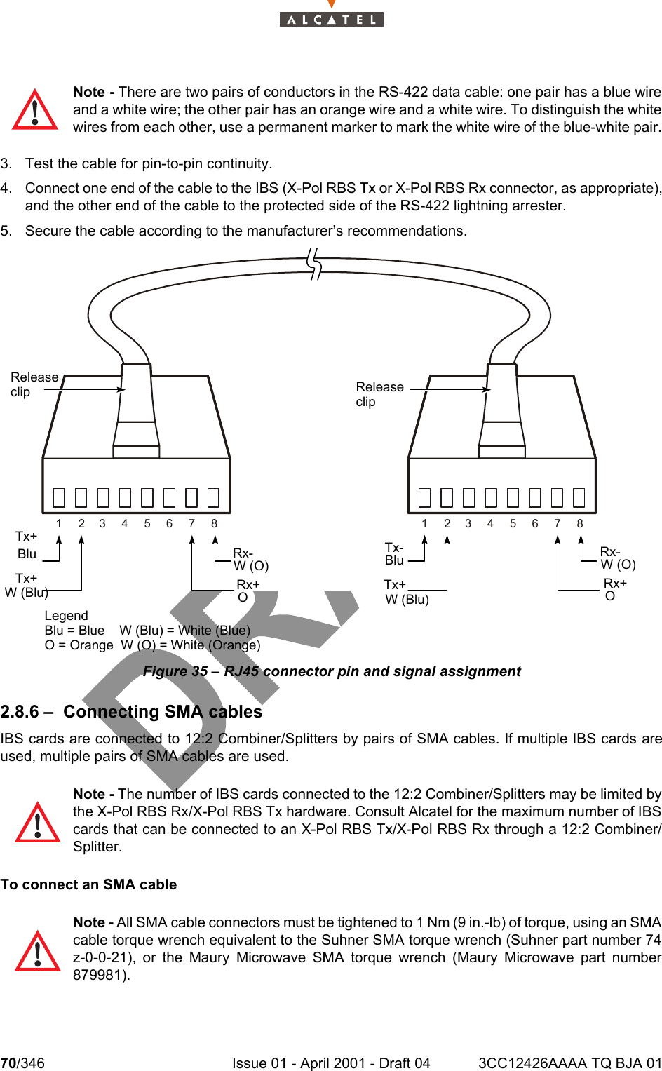
![60/346 Issue 01 - April 2001 - Draft 04 3CC12426AAAA TQ BJA 01104where Losstotal is the loss of the IF cable run in dB/100 m (dB/100 ft) Lossi is the loss of the indoor-rated cable (in dB)Losso is the loss of the outdoor-rated cable (in dB)Lossi connector is the loss of the indoor cable connector (in dB)Losso connector is the loss of the outdoor cable connector (in dB)After all components have been installed and connected, system loss measurements and calibrationmust be made to determine the actual losses. If the measured loss is greater than the required loss,different cable types may be necessary. If the measured loss is less than the required value, attenuatorsshould be added between the 12:2 Combiner/Splitter and the Bias-T. See chapter 11 for measurementand calibration procedures.Table 19: BS passive device and IF cable lossesNote: (1) Measured at 2050 MHz.(2) Measured at 900 MHz.(3) The values given are for the sum of the indoor and outdoor cable runs, excluding the outdoorIF jumper cable. The values include four connectors, two for the indoor cable and two for theoutdoor cable.BS componentTotal downstream loss (1) (dB)Total upstream loss (2) (dB)Fixed loss requirement 27 24Component SMA jumper cable (3 m [10 ft]) 1.0 1.0Tx 12:2 Combiner/Splitter 17.10 N/ARx 12:2 Combiner/Splitter N/A 17.10Bias-T 1.03 1.03Lightning arrester 0.20 0.20Outdoor IF jumper cable (including con-nectors)0.3 0.3Total loss due to all components except IF cables 19.63 19.63Loss available for IF cable(3) (fixed loss requirement minus total component loss) 7.37 4.37](https://usermanual.wiki/Alcatel-Canada/39T28A03A22A.Base-Station-User-Manual-2-of-14/User-Guide-175935-Page-20.png)
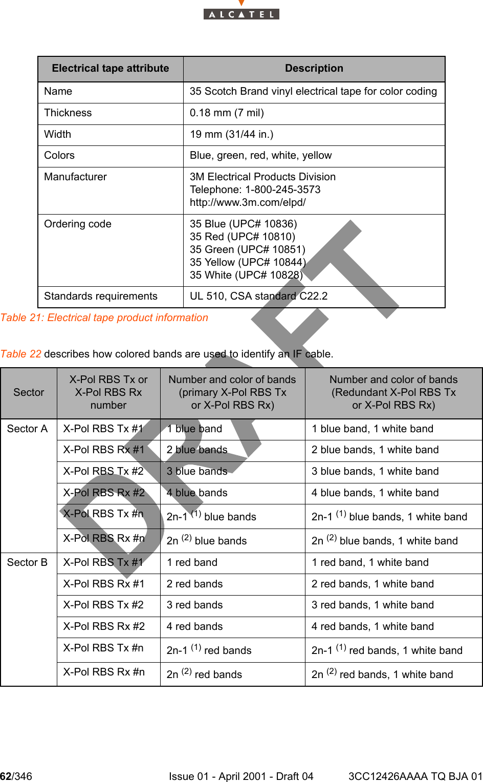
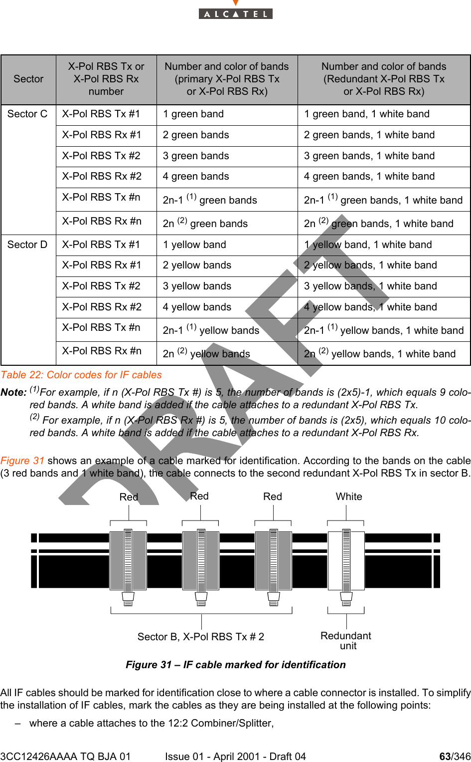
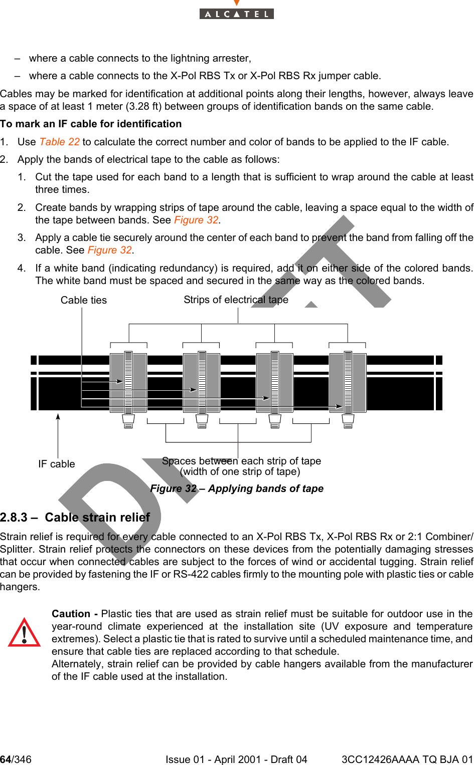
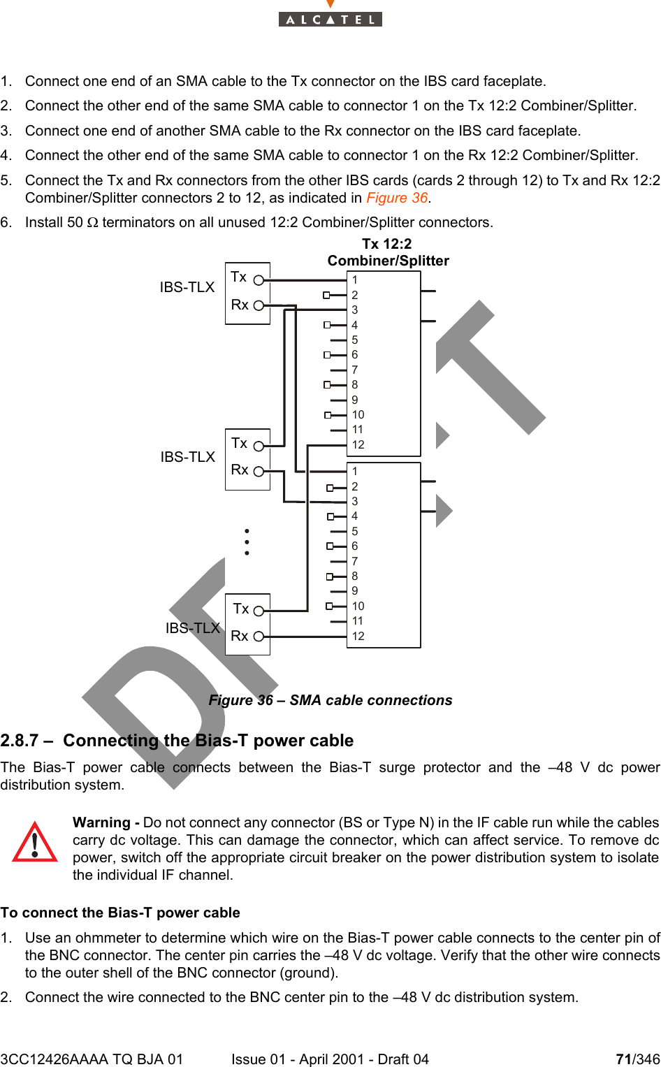
![3CC12426AAAA TQ BJA 01 Issue 01 - April 2001 - Draft 04 61/346104Table 20: IF cable loss characteristics, types and connectorsNote: Measured at 2050 MHz.Measured at 900 MHz.2.8.2 – Marking IF cables for identificationIF cables must be marked to indicate which X-Pol RBS Tx or X-Pol RBS Rx each cable connects to. Itis recommended that you use bands of electrical tape to identify each cable:– the tape color (blue, red, green or yellow) indicates the sector,– the number of colored bands of tape indicates the X-Pol RBS Tx or X-Pol RBS Rx number in thesector,– a white band on either side of the colored bands indicates that the IF cable connects to a redun-dant X-Pol RBS Tx or X-Pol RBS Rx.Table 21 describes the electrical tape recommended for marking IF cables. Cable typeConnector Loss (dB/100 m [dB/100 ft])RatingType Loss (dB) Downstream (1) Upstream (2)IndoorHeliax FSJ1-50A F1PNM 0.05 29.03 (8.85) 18.59 (5.66) IndoorHeliax FSJ2-50 F2PNM 0.05 19.99 (6.09) 12.65 (3.86) IndoorHeliax FSJ4-50 BF4PNM 0.05 17.76 (5.39) 11.07 (3.38) IndoorHeliax HL4-RP-50 H4PNM 0.08 12.22 (3.91) 8.24 (2.51) Indoor/plenumHeliax HJ5-50 H5PNM 0.08 6.07 (1.88) 3.92 (1.19) Indoor/plenumTimes Microwave LMR-400 Ultra Flex TC-400-NMH 0.10 23.82 (7.26) 15.39 (4.69) IndoorTimes Microwave LMR-600-LLPL TC-600-NMH 0.10 13.09 (3.99) 8.45 (2.57) Plenum/outdoorTimes Microwave LMR-900-FR EZ-900-NMH 0.10 8.76 (2.67) 5.56 (1.69) IndoorOutdoorHeliax LDF2-50 L2PNM 0.05 16.98 (5.18) 10.88 (3.32) OutdoorHeliax LDF4-50A L4PNM 0.05 11.48 (3.50) 7.23 (2.20) OutdoorHeliax LDF5-50A L5PNM 0.05 6.56 (2.00) 4.04 (1.23) OutdoorHeliax LDF6-50 L6PNM 0.05 4.83 (1.47) 2.98 (0.91) OutdoorCommScope CR50-540-PE CR540NM 0.10 10.4 (4.16) 6.59 (2.01) OutdoorCommScope CR50-1070-PE CR1070NM 0.10 5.90 (1.80) 3.61 (1.10) OutdoorTimes Microwave LMR-600-LLPL TC-600-NMH 0.10 13.09 (3.99) 8.45 (2.57) Plenum/outdoor](https://usermanual.wiki/Alcatel-Canada/39T28A03A22A.Base-Station-User-Manual-2-of-14/User-Guide-175935-Page-21.png)
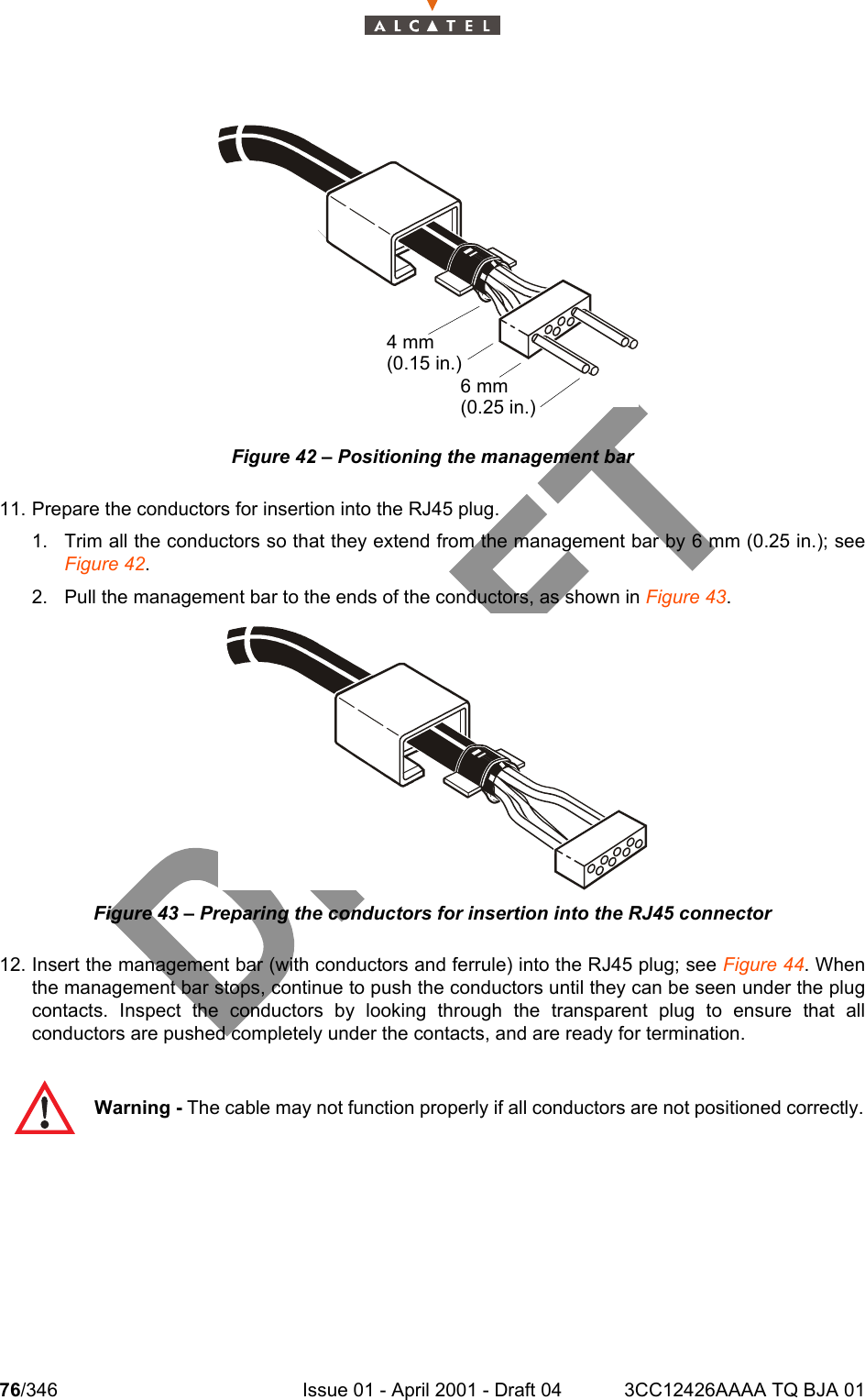
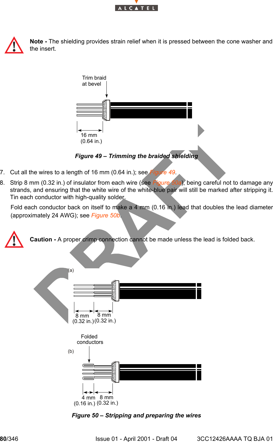
![3CC12426AAAA TQ BJA 01 Issue 01 - April 2001 - Draft 04 75/346104Figure 41 – Inserting the conductors into the management barTable 25 RS-422 cable pin and signal assignments10. Slide the management bar towards the cable jacket until there is no more than 4 mm (0.15 in.)between the bar and the jacket; see Figure 42. PinSignalRJ45 connector LEMO connector13Tx-21Tx+72Rx+84Rx-Note - The cable may not work properly if the distance between the management bar andthe cable jacket is greater than 4 mm (0.15 in.).ManagementbarPin 2Tx+ (W[Blu])Pin 1Tx- BluPin 8Rx- (W[O]Pin 7Rx+ (O)](https://usermanual.wiki/Alcatel-Canada/39T28A03A22A.Base-Station-User-Manual-2-of-14/User-Guide-175935-Page-35.png)