Alcatel Canada 24T28A01D22C 7390 24 GHz Co-Pol RBS User Manual BS Manual pages 71 to 76

Alcatel Canada Inc 7390 24 GHz Co-Pol RBS BS Manual pages 71 to 76

BS Manual pages 71 to 76

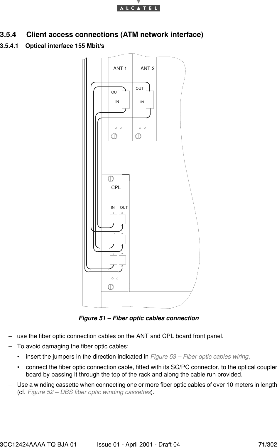
3CC12424AAAA TQ BJA 01 Issue 01 - April 2001 - Draft 04 71/302763.5.4 Client access connections (ATM network interface)3.5.4.1 Optical interface 155 Mbit/sFigure 51 – Fiber optic cables connection–use the fiber optic connection cables on the ANT and CPL board front panel.–To avoid damaging the fiber optic cables:•insert the jumpers in the direction indicated in Figure 53 – Fiber optic cables wiring,•connect the fiber optic connection cable, fitted with its SC/PC connector, to the optical couplerboard by passing it through the top of the rack and along the cable run provided.–Use a winding cassette when connecting one or more fiber optic cables of over 10 meters in length(cf. Figure 52 – DBS fiber optic winding cassettes).ANT 2ANT 1INOUT OUTININ OUTCPL
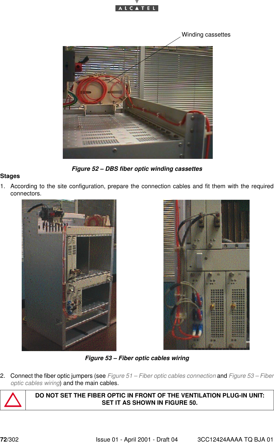
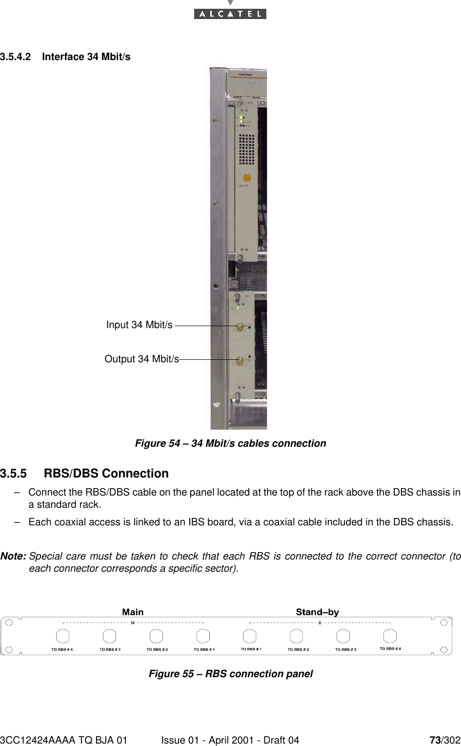
72/302 Issue 01 - April 2001 - Draft 04 3CC12424AAAA TQ BJA 0176Figure 52 – DBS fiber optic winding cassettesStages1. According to the site configuration, prepare the connection cables and fit them with the requiredconnectors.Figure 53 – Fiber optic cables wiring2. Connect the fiber optic jumpers (see Figure 51 – Fiber optic cables connection and Figure 53 – Fiberoptic cables wiring) and the main cables.DO NOT SET THE FIBER OPTIC IN FRONT OF THE VENTILATION PLUG-IN UNIT:SET IT AS SHOWN IN FIGURE 50.Winding cassettes
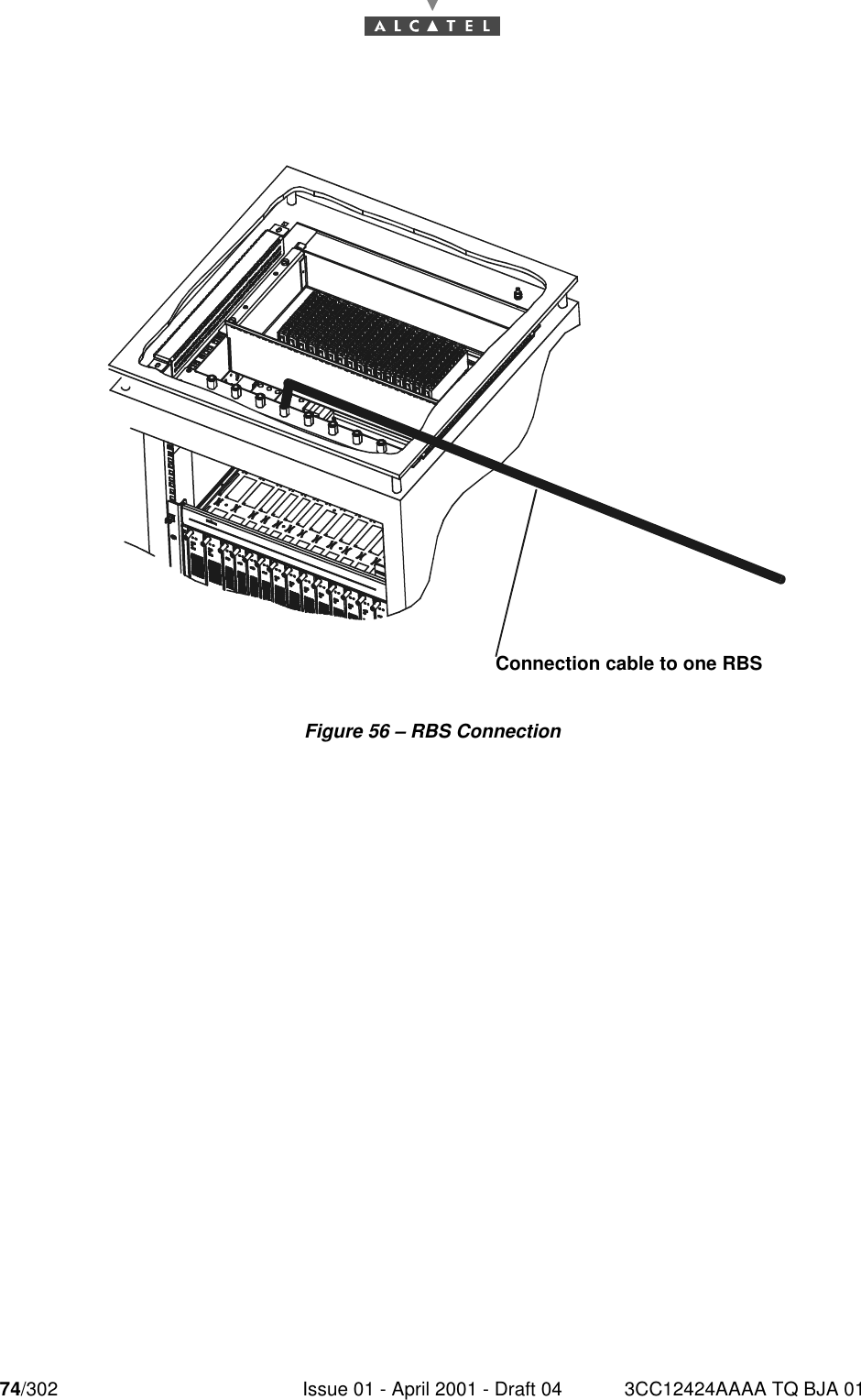
3CC12424AAAA TQ BJA 01 Issue 01 - April 2001 - Draft 04 73/302763.5.4.2 Interface 34 Mbit/sFigure 54 – 34 Mbit/s cables connection3.5.5 RBS/DBS Connection–Connect the RBS/DBS cable on the panel located at the top of the rack above the DBS chassis ina standard rack.–Each coaxial access is linked to an IBS board, via a coaxial cable included in the DBS chassis.Note: Special care must be taken to check that each RBS is connected to the correct connector (toeach connector corresponds a specific sector).Figure 55 – RBS connection panelInput 34 Mbit/s Output 34 Mbit/s
74/302 Issue 01 - April 2001 - Draft 04 3CC12424AAAA TQ BJA 0176Figure 56 – RBS ConnectionConnection cable to one RBS
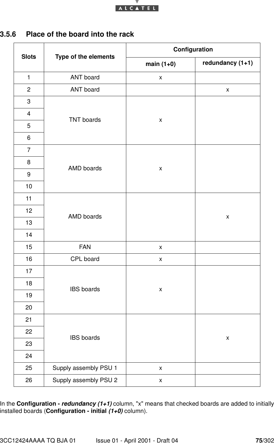
3CC12424AAAA TQ BJA 01 Issue 01 - April 2001 - Draft 04 75/302763.5.6 Place of the board into the rackIn the Configuration - redundancy (1+1) column, "x" means that checked boards are added to initiallyinstalled boards (Configuration - initial (1+0) column).Slots Type of the elements Configurationmain (1+0) redundancy (1+1)1 ANT board x2 ANT board x3TNT boards x4567AMD boards x891011AMD boards x12131415 FAN x16 CPL board x17IBS boards x18192021IBS boards x22232425 Supply assembly PSU 1 x26 Supply assembly PSU 2 x
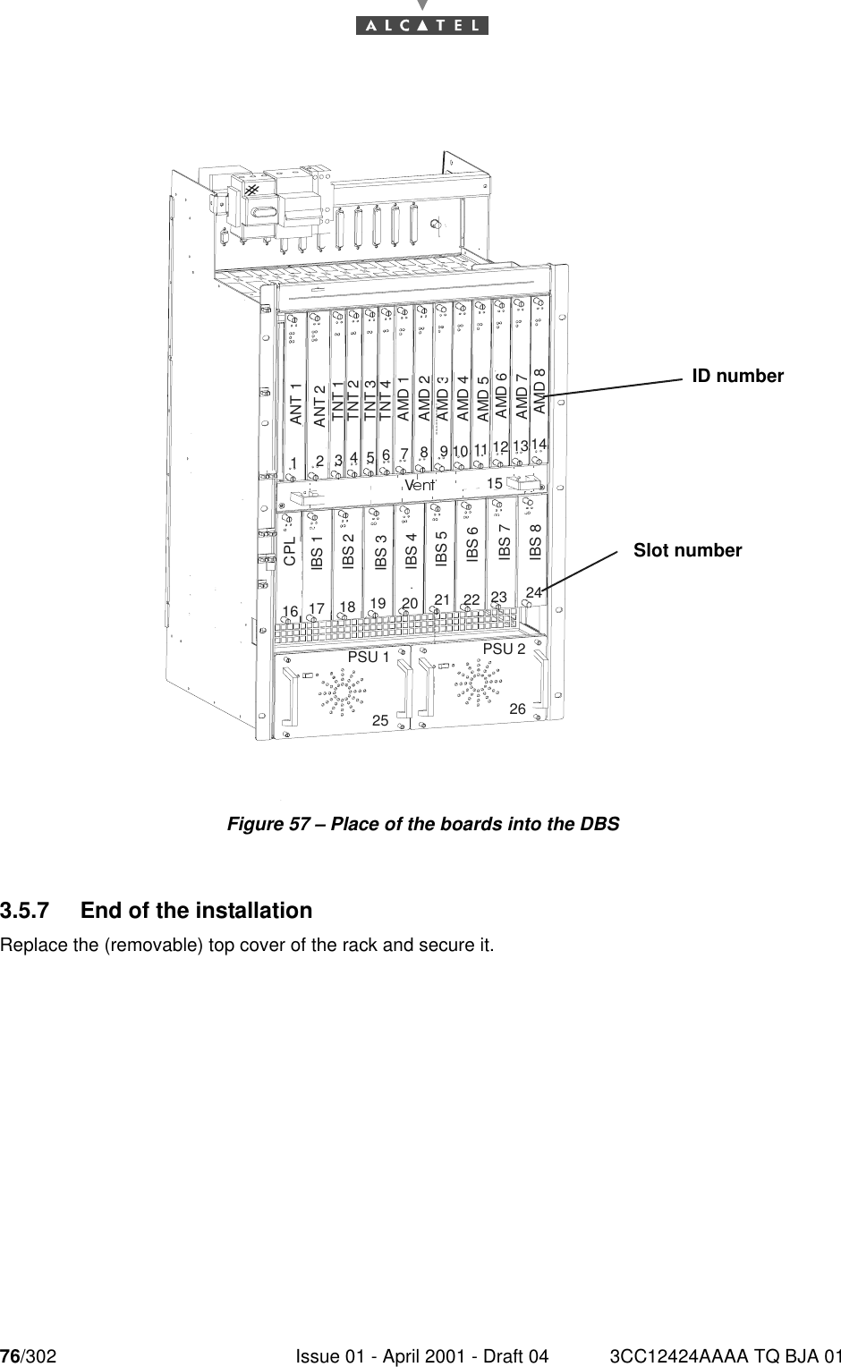
76/302 Issue 01 - April 2001 - Draft 04 3CC12424AAAA TQ BJA 0176Figure 57 – Place of the boards into the DBS3.5.7 End of the installationReplace the (removable) top cover of the rack and secure it.ANT 1ANT 2TNT 1TNT 2TNT 3TNT 4AMD 1AMD 2AMD 3AMD 4CPLIBS 1IBS 2IBS 3IBS 4PSU 1 PSU 2V127346510981311 1412151716 1918 2025232221 2426IBS 5IBS 6IBS 7IBS 8AMD 5AMD 6AMD 7AMD 8ID numberSlot number

Navigation menu