Alcatel Canada 24T28A01D22C 7390 24 GHz Co-Pol RBS User Manual BS Manual pages 285 to 302

Alcatel Canada Inc 7390 24 GHz Co-Pol RBS BS Manual pages 285 to 302

BS Manual pages 285 to 302
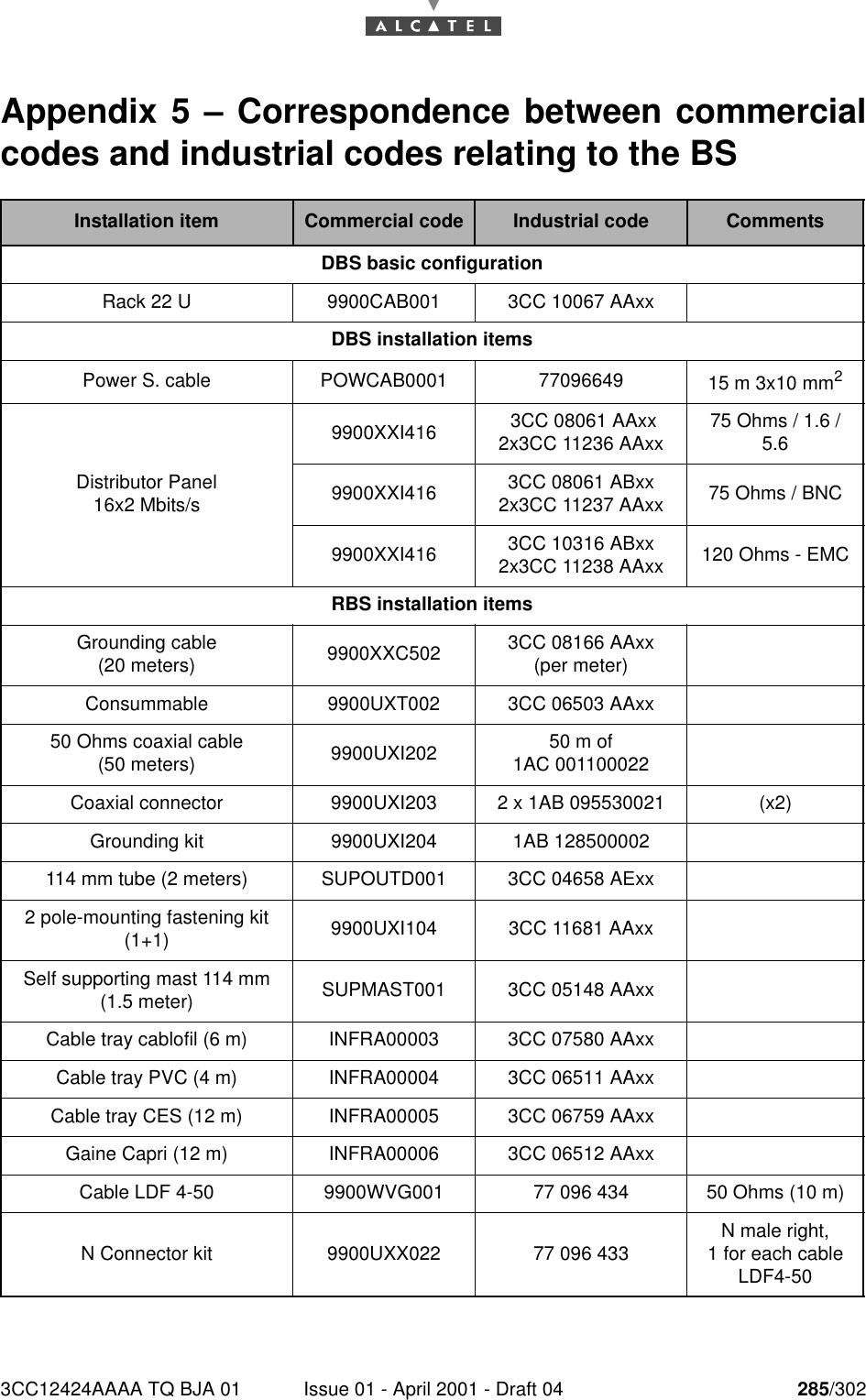
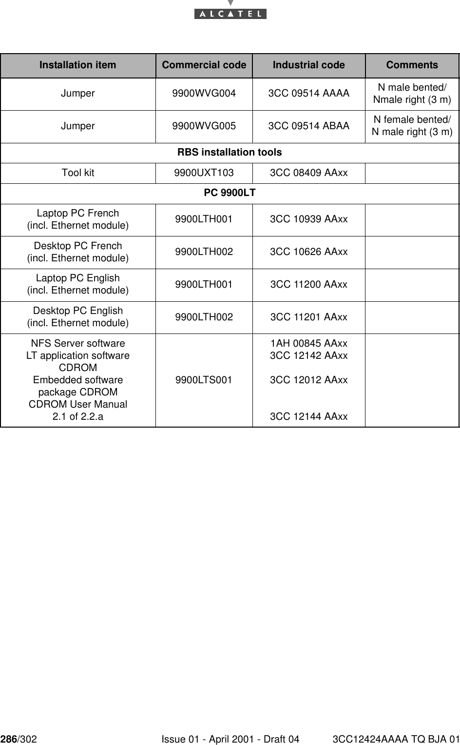
3CC12424AAAA TQ BJA 01 Issue 01 - April 2001 - Draft 04 285/302286Appendix 5 – Correspondence between commercialcodes and industrial codes relating to the BS   Installation item Commercial code Industrial code CommentsDBS basic configurationRack 22 U 9900CAB001 3CC 10067 AAxxDBS installation itemsPower S. cable POWCAB0001 77096649 15 m 3x10 mm2Distributor Panel16x2 Mbits/s9900XXI416  3CC 08061 AAxx2x3CC 11236 AAxx 75 Ohms / 1.6 / 5.69900XXI416 3CC 08061 ABxx2x3CC 11237 AAxx 75 Ohms / BNC9900XXI416 3CC 10316 ABxx2x3CC 11238 AAxx 120 Ohms - EMCRBS installation itemsGrounding cable(20 meters) 9900XXC502 3CC 08166 AAxx(per meter)Consummable 9900UXT002 3CC 06503 AAxx50 Ohms coaxial cable(50 meters) 9900UXI202 50 m of1AC 001100022Coaxial connector 9900UXI203 2 x 1AB 095530021 (x2)Grounding kit   9900UXI204 1AB 128500002114 mm tube (2 meters) SUPOUTD001 3CC 04658 AExx2 pole-mounting fastening kit(1+1) 9900UXI104 3CC 11681 AAxxSelf supporting mast 114 mm (1.5 meter) SUPMAST001 3CC 05148 AAxxCable tray cablofil (6 m) INFRA00003 3CC 07580 AAxxCable tray PVC (4 m)   INFRA00004 3CC 06511 AAxxCable tray CES (12 m)   INFRA00005 3CC 06759 AAxxGaine Capri (12 m)   INFRA00006 3CC 06512 AAxxCable LDF 4-50    9900WVG001 77 096 434 50 Ohms (10 m)N Connector kit   9900UXX022 77 096 433  N male right,1 for each cable LDF4-50
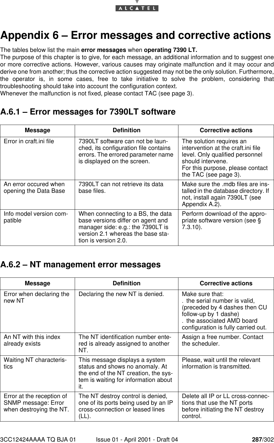
286/302 Issue 01 - April 2001 - Draft 04 3CC12424AAAA TQ BJA 01286Installation item Commercial code Industrial code CommentsJumper 9900WVG004 3CC 09514 AAAA  N male bented/Nmale right (3 m)Jumper   9900WVG005 3CC 09514 ABAA N female bented/N male right (3 m)RBS installation toolsTool kit 9900UXT103 3CC 08409 AAxxPC 9900LTLaptop PC French(incl. Ethernet module) 9900LTH001 3CC 10939 AAxxDesktop PC French (incl. Ethernet module) 9900LTH002 3CC 10626 AAxxLaptop PC English(incl. Ethernet module) 9900LTH001 3CC 11200 AAxxDesktop PC English(incl. Ethernet module) 9900LTH002 3CC 11201 AAxxNFS Server softwareLT application software CDROMEmbedded softwarepackage CDROMCDROM User Manual2.1 of 2.2.a9900LTS0011AH 00845 AAxx3CC 12142 AAxx3CC 12012 AAxx3CC 12144 AAxx
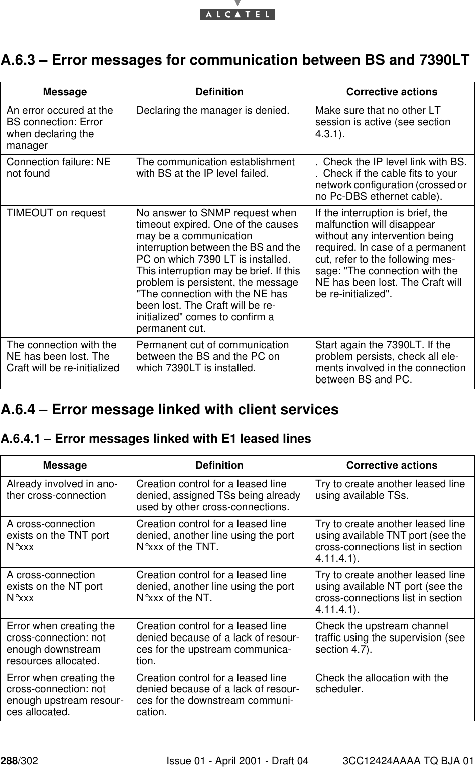
3CC12424AAAA TQ BJA 01 Issue 01 - April 2001 - Draft 04 287/302292Appendix 6 – Error messages and corrective actionsThe tables below list the main error messages when operating 7390 LT.The purpose of this chapter is to give, for each message, an additional information and to suggest oneor more corrective actions. However, various causes may originate malfunction and it may occur andderive one from another; thus the corrective action suggested may not be the only solution. Furthermore,the operator is, in some cases, free to take initiative to solve the problem, considering thattroubleshooting should take into account the configuration context.Whenever the malfunction is not fixed, please contact TAC (see page 3).A.6.1 – Error messages for 7390LT softwareA.6.2 – NT management error messagesMessage Definition Corrective actionsError in craft.ini file 7390LT software can not be laun-ched, its configuration file contains errors. The errored parameter name is displayed on the screen.The solution requires an intervention at the craft.ini file level. Only qualified personnel should intervene.For this purpose, please contact the TAC (see page 3).An error occured when opening the Data Base 7390LT can not retrieve its data base files. Make sure the .mdb files are ins-talled in the database directory. If not, install again 7390LT (see Appendix A.2).Info model version com-patible When connecting to a BS, the data base versions differ on agent and manager side: e.g.: the 7390LT is version 2.1 whereas the base sta-tion is version 2.0.Perform download of the appro-priate software version (see § 7.3.10).Message Definition Corrective actionsError when declaring the new NT Declaring the new NT is denied. Make sure that:.the serial number is valid, (preceded by 4 dashes then CU follow-up by 1 dashe).the associated AMD board configuration is fully carried out.An NT with this index already exists The NT identification number ente-red is already assigned to another NT.Assign a free number. Contact the scheduler.Waiting NT characteris-tics This message displays a system status and shows no anomaly. At the end of the NT creation, the sys-tem is waiting for information about it.Please, wait until the relevant information is transmitted.Error at the reception of SNMP message: Error when destroying the NT.The NT destroy control is denied, one of its ports being used by an IP cross-connection or leased lines (LL).Delete all IP or LL cross-connec-tions that use the NT ports before initiating the NT destroy control.
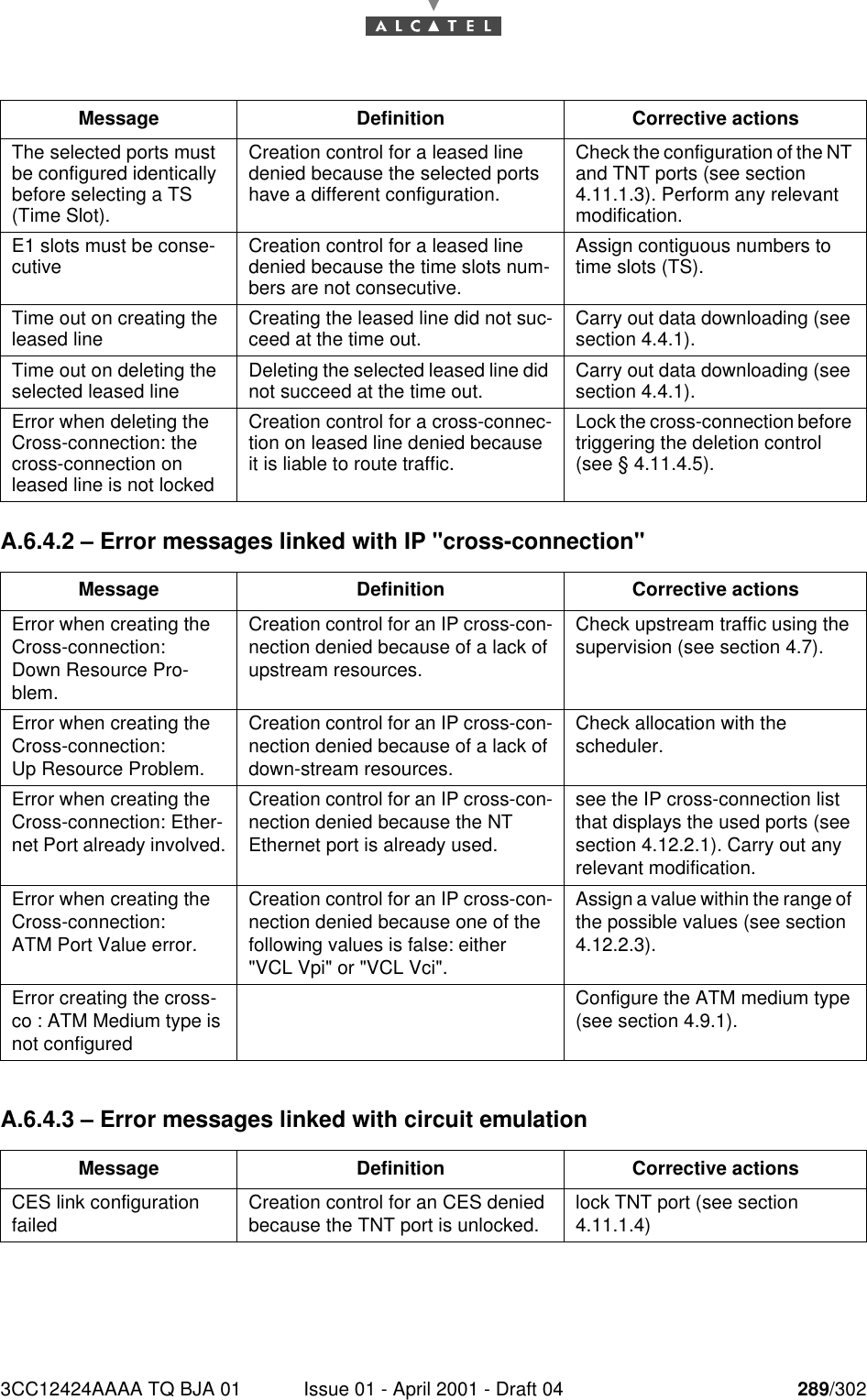
288/302 Issue 01 - April 2001 - Draft 04 3CC12424AAAA TQ BJA 01292A.6.3 – Error messages for communication between BS and 7390LTA.6.4 – Error message linked with client servicesA.6.4.1 – Error messages linked with E1 leased linesMessage Definition Corrective actionsAn error occured at the BS connection: Error when declaring the managerDeclaring the manager is denied. Make sure that no other LT session is active (see section 4.3.1).Connection failure: NE not found The communication establishment with BS at the IP level failed. .Check the IP level link with BS..Check if the cable fits to your network configuration (crossed or no Pc-DBS ethernet cable).TIMEOUT on request No answer to SNMP request when timeout expired. One of the causes may be a communication interruption between the BS and the PC on which 7390 LT is installed.This interruption may be brief. If this problem is persistent, the message "The connection with the NE has been lost. The Craft will be re-initialized" comes to confirm a permanent cut.If the interruption is brief, the malfunction will disappear without any intervention being required. In case of a permanent cut, refer to the following mes-sage: "The connection with the NE has been lost. The Craft will be re-initialized".The connection with the NE has been lost. The Craft will be re-initializedPermanent cut of communication between the BS and the PC on which 7390LT is installed.Start again the 7390LT. If the problem persists, check all ele-ments involved in the connection between BS and PC.Message Definition Corrective actionsAlready involved in ano-ther cross-connection Creation control for a leased line denied, assigned TSs being already used by other cross-connections.Try to create another leased line using available TSs.A cross-connection exists on the TNT port N°xxxCreation control for a leased line denied, another line using the port N°xxx of the TNT.Try to create another leased line using available TNT port (see the cross-connections list in section 4.11.4.1).A cross-connection exists on the NT port N°xxxCreation control for a leased line denied, another line using the port N°xxx of the NT.Try to create another leased line using available NT port (see the cross-connections list in section 4.11.4.1).Error when creating the cross-connection: not enough downstream resources allocated.Creation control for a leased line denied because of a lack of resour-ces for the upstream communica-tion.Check the upstream channel traffic using the supervision (see section 4.7).Error when creating the cross-connection: not enough upstream resour-ces allocated.Creation control for a leased line denied because of a lack of resour-ces for the downstream communi-cation.Check the allocation with the scheduler.
3CC12424AAAA TQ BJA 01 Issue 01 - April 2001 - Draft 04 289/302292A.6.4.2 – Error messages linked with IP "cross-connection"A.6.4.3 – Error messages linked with circuit emulationThe selected ports must be configured identically before selecting a TS (Time Slot).Creation control for a leased line denied because the selected ports have a different configuration.Check the configuration of the NT and TNT ports (see section 4.11.1.3). Perform any relevant modification.E1 slots must be conse-cutive Creation control for a leased line denied because the time slots num-bers are not consecutive.Assign contiguous numbers to time slots (TS).Time out on creating the leased line Creating the leased line did not suc-ceed at the time out. Carry out data downloading (see section 4.4.1).Time out on deleting the selected leased line Deleting the selected leased line did not succeed at the time out. Carry out data downloading (see section 4.4.1).Error when deleting the Cross-connection: the cross-connection on leased line is not lockedCreation control for a cross-connec-tion on leased line denied because it is liable to route traffic.Lock the cross-connection before triggering the deletion control (see § 4.11.4.5).Message Definition Corrective actionsError when creating the Cross-connection:Down Resource Pro-blem.Creation control for an IP cross-con-nection denied because of a lack of upstream resources.Check upstream traffic using the supervision (see section 4.7).Error when creating the Cross-connection:Up Resource Problem.Creation control for an IP cross-con-nection denied because of a lack of down-stream resources.Check allocation with the scheduler.Error when creating the Cross-connection: Ether-net Port already involved.Creation control for an IP cross-con-nection denied because the NT Ethernet port is already used.see the IP cross-connection list that displays the used ports (see section 4.12.2.1). Carry out any relevant modification.Error when creating the Cross-connection:ATM Port Value error.Creation control for an IP cross-con-nection denied because one of the following values is false: either "VCL Vpi" or "VCL Vci".Assign a value within the range of the possible values (see section 4.12.2.3).Error creating the cross-co : ATM Medium type is not configuredConfigure the ATM medium type (see section 4.9.1).Message Definition Corrective actionsCES link configuration failed Creation control for an CES denied because the TNT port is unlocked. lock TNT port (see section 4.11.1.4)Message Definition Corrective actions
290/302 Issue 01 - April 2001 - Draft 04 3CC12424AAAA TQ BJA 01292A.6.5 – Download error messagesA.6.6 – Error message at backup / restoreA.6.7 – Error messages for radio managementA.6.7.1 – Error messages linked to the radio configurationA.6.7.2 – Radio Resources Manager (RRM)Message Definition Corrective actionsSoftware download done with problems detected. An error occurred during data down-load. .Check the NFS server status is operational,.Chek hardware description for the BS boards..Check the exported directory has been added to the omni-NFS server during a session with adminis-trator rights.Package commit done with problems. An error occurred during referen-cing. Check for any current board alarms. If so, rectify the problem in all cases (whether or not the card presented an alarm) carry out again a complete download.Message Definition Corrective actionsError when transfering the sRam File NFS server problem (directory not recognized by the server) Export the directory in R/W to the NFS server.Message Definition Corrective actionsError when setting the radiolink characteristics The modification of the radio link characteristics displayed cannot be taken into account.Before modifying the bandwidth, suppress the NTs linked to this radio link (see 4.6.3)Message Definition Corrective actionsBad static Value down-stream Inconsistency between the services already created and the modified static zone in the downstream- Cancel the modification- Update the static zone with avalue compatible with the staticservices already createdBad static Value ups-tream Inconsistency between the services already created and the modified static zone in the upstream (x from 1 to 4)- Cancel the modification- Update the static zone with avalue compatible with the staticservices already createdBad dynamic max Value downstream Inconsistency between the services already created and the modified dynamic zone in the downstream.Update the dynamic zone with a value compatible with the dynamic service already created and the overbooking factor limit
3CC12424AAAA TQ BJA 01 Issue 01 - April 2001 - Draft 04 291/302292A.6.8 – ASAP error messagesA.6.9 – Miscellaneous error messagesBad dynamic Value ups-tream x Inconsistency between the services already created and the modified dynamic zone in the upstream.Update the dynamic zone with a value compatible with the dynamic service already created and the overbooking factor limitBad dynamic max Value upstream x (x from 1 to 4)  Update over booking factor limit with a value compatible with the dynamic services created and the dynamic zone.Message Definition Corrective actionsError removing ASAP The ASAP cannot be removed because at least one NT is attached to the ASAP table.Before removing, the ASAP table has to be deleted for each NT attached to the table.Message Definition Corrective actionsError when destroying the board Board deletion control denied.  The corrective action is related tothe type of board:.AMD board: make sure that noNT is associated with the board..TNT board: make sure that noport is used either by a leasedline or as a potential source ofsynchronization..NT board: make sure that noport is used either by a leasedline or by an IP cross-connection.Error when modifying the TNT board The modification of the TNT board characteristics cannot be taken into account.All circuit emulation services must be suppressed before modifying the configuration of a TNT board.Error when updating the BS In BS’s local network screen one parameter is not correct. - Check that BS’s IP address is areal IP address.- Check that Ethernet and ATMnetworks are different.Error when setting syn-chro parameters Synchronization configuration is not allowed.  Check that the reserved chan-nels are configured (see § 4.11).Error when enabling/ disabling E1 traffic on a TNT portEnabling/disabling is not allowed. If the TNT port is used for system synchronization, the TNT port cannot be locked.Message Definition Corrective actions
292/302 Issue 01 - April 2001 - Draft 04 3CC12424AAAA TQ BJA 01292PAGE INTENTIONALLY LEFT BLANK
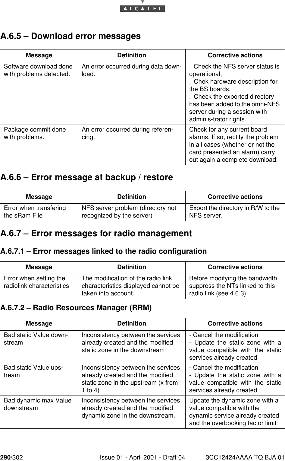
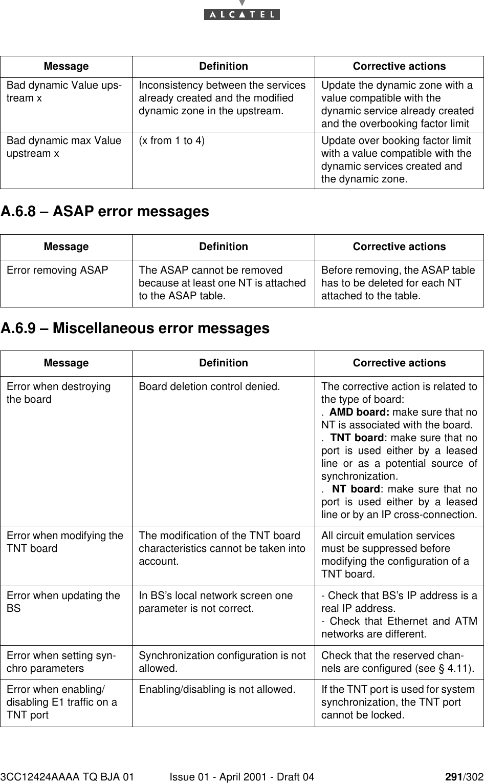
3CC12424AAAA TQ BJA 01 Issue 01 - April 2001 - Draft 04 293/302298Appendix 7 – Pole mounting 9900UXI101A.7.1 – DefinitionFigure 61 – Definition of 7390BS outdoor equipmentFigure 62 – Dimensions of the RBS on pole mounting (99UXI101)SectoredantennaTransceiverTube ou poleRBS/DBS connection cableMechanical polemounting(9900UXI101)RBS288.2 238689.3503.4
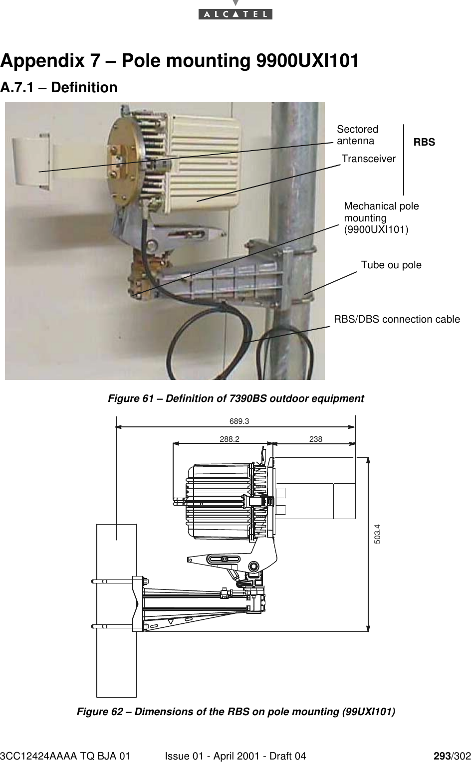
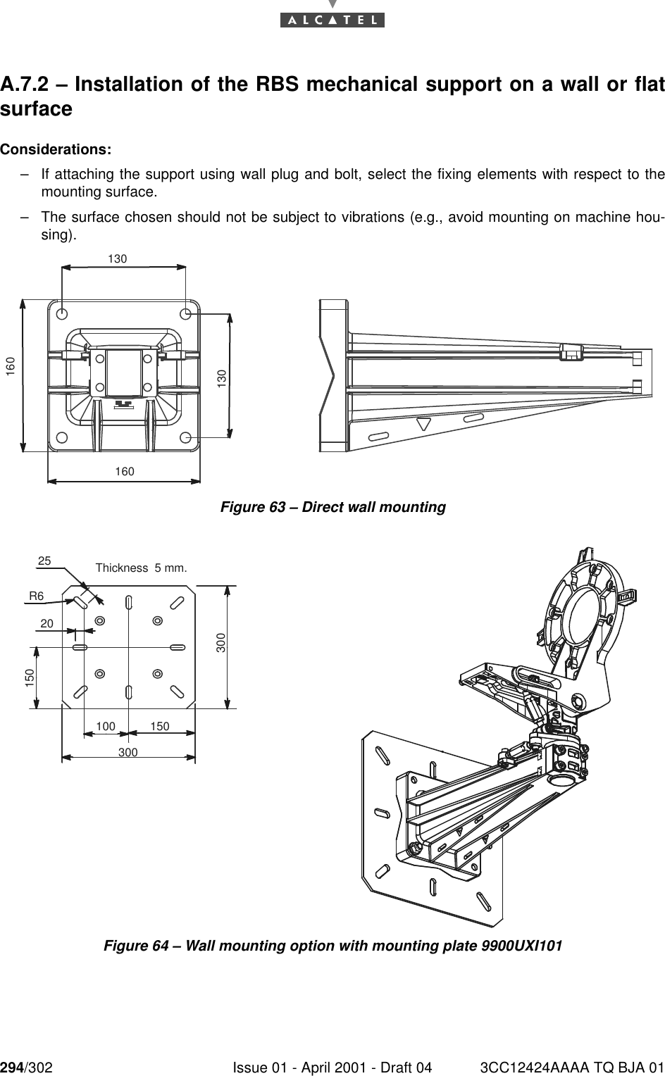
294/302 Issue 01 - April 2001 - Draft 04 3CC12424AAAA TQ BJA 01298A.7.2 – Installation of the RBS mechanical support on a wall or flatsurfaceConsiderations:–If attaching the support using wall plug and bolt, select the fixing elements with respect to themounting surface.–The surface chosen should not be subject to vibrations (e.g., avoid mounting on machine hou-sing).Figure 63 – Direct wall mountingFigure 64 – Wall mounting option with mounting plate 9900UXI101130160130160300100 1503002520150R6Thickness  5 mm.
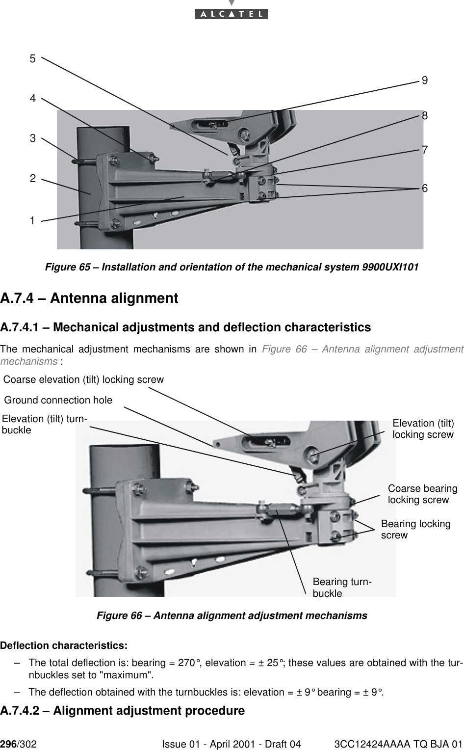
3CC12424AAAA TQ BJA 01 Issue 01 - April 2001 - Draft 04 295/302298Stages1. Select the installation location.2. Drill 4 holes according to the dimensions given in Figure 63 – Direct wall mounting.3. Insert 4 wall plugs.4. Install and secure the wall support using 4 x M10 screws with washers.A.7.3  – Installation and orientation of the mechanical system(9900UXI101)Considerations–Installation can be carried out on an existing or newly installed tube or pole.–The external diameter of the tube or pole is maximum 114 mm in standard configuration.Note: Other tube diameters may be used depending on the loads to be supported: minimum diameter76 mm and maximum 114 mm.–The tube or pole along with the U-bolts must be clean and (apart from threads) grease-free.–Wall mounting possible with or without wall plate: see Figure 63 – Direct wall mounting and Figure64 – Wall mounting option with mounting plate 9900UXI101.Stages (Figure 65 – Installation and orientation of the mechanical system 9900UXI101)1. On the pole mounting (ref. 1), loosen the four "bearing" locking screws (ref. 6) and the coarse"bearing" locking screw (ref. 7) to facilitate the subsequent RBS unit mounting.2. Fit the pole mounting (ref. 1) on the tube or pole (ref. 2) using the U-bolts (ref. 3). Secure it using flatwashers, "grower" washers, nuts and lock-nuts (ref. 4).3. Roughly orientate the bearing of the pole mounting in the desired topographical direction. Thebearing turnbuckle (ref. 8) should remain in mid-position. Use the "top" marking of the antenna anda compass, then tighten the U-bolts (ref. 3). U-bolt tightening torque = 3daN.m.4. Roughly orientate the elevation of the antenna support by loosening the "elevation" locking screw(ref. 9). The elevation turnbuckle (ref. 5) should remain in mid-position; pivot the antenna supportthrough the vertical to adjust, then tighten the "elevation" locking screw (ref. 9).IMPORTANT: THIS MUST NOT DEPART FROM ± 1° TO THE VERTICAL FORTHE PURPOSE OF POLARISATIONUSE BOLT SIZE M10 (MINIMUM 10 mm DIAMETER). CHECK RELEVANT LOCAL REGULATIONS BEFORE INSTALLING.VERTICALITY OF THE BEARING: ± 0.5 ° FOR STANDARD ANTENNAS.± 0,25 ° FOR LARGE GAIN ANTENNAS.NEVER INSTALL THE BEARING AXIS HORIZONTALLY; THE RBS UNITS MUSTBE ABOVE THE POLE MOUNTING AND NOT PROJECT LATERALLY.
296/302 Issue 01 - April 2001 - Draft 04 3CC12424AAAA TQ BJA 01298Figure 65 – Installation and orientation of the mechanical system 9900UXI101A.7.4 – Antenna alignmentA.7.4.1 – Mechanical adjustments and deflection characteristicsThe mechanical adjustment mechanisms are shown in Figure 66 – Antenna alignment adjustmentmechanisms :Figure 66 – Antenna alignment adjustment mechanismsDeflection characteristics:–The total deflection is: bearing = 270°, elevation = ± 25°; these values are obtained with the tur-nbuckles set to "maximum".–The deflection obtained with the turnbuckles is: elevation = ± 9° bearing = ± 9°.A.7.4.2 – Alignment adjustment procedure247389651Coarse elevation (tilt) locking screwCoarse bearinglocking screwBearing lockingscrewBearing turn-buckleGround connection holeElevation (tilt) turn-buckle Elevation (tilt)locking screw
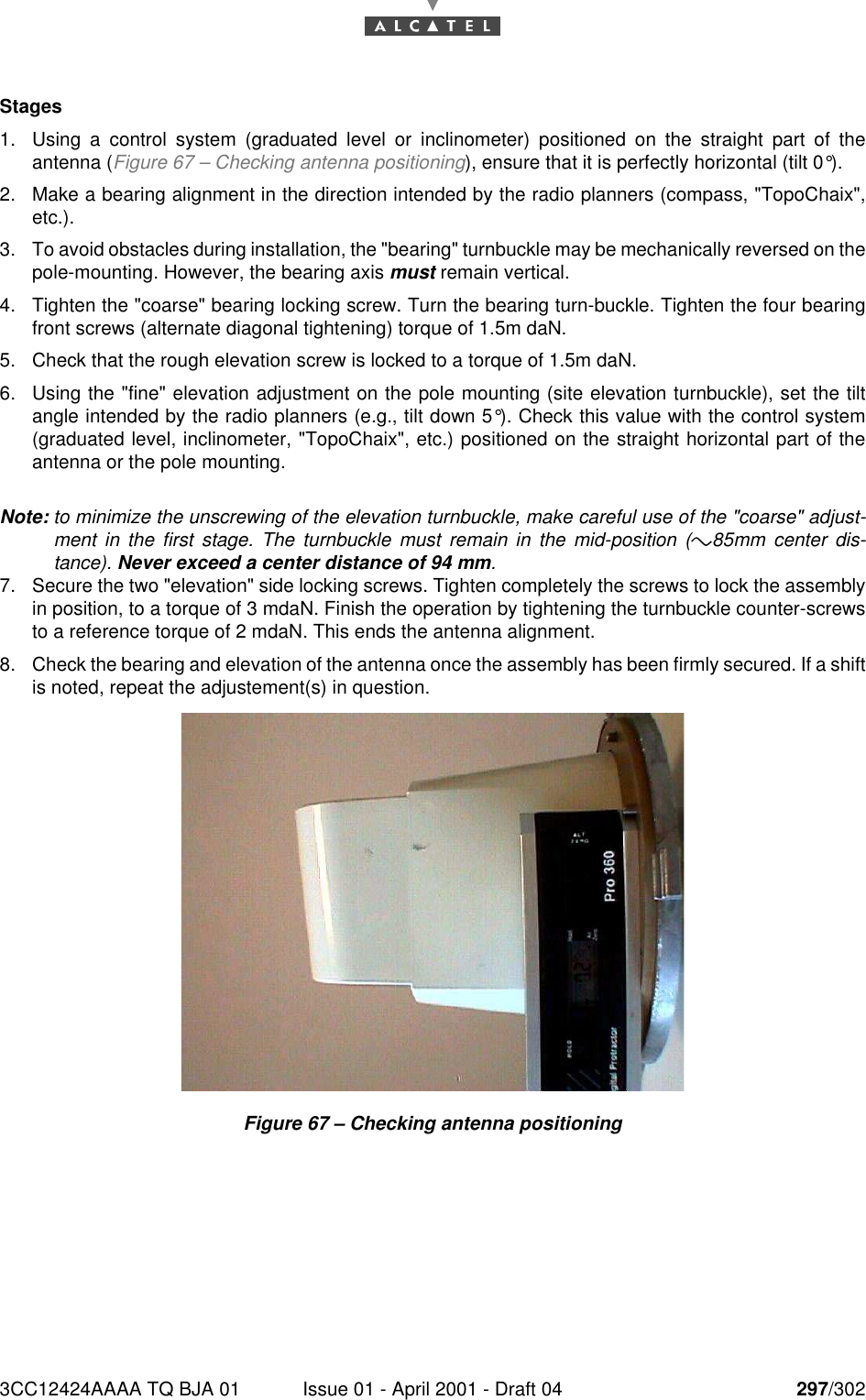
3CC12424AAAA TQ BJA 01 Issue 01 - April 2001 - Draft 04 297/302298Stages1. Using a control system (graduated level or inclinometer) positioned on the straight part of theantenna (Figure 67 – Checking antenna positioning), ensure that it is perfectly horizontal (tilt 0°).2. Make a bearing alignment in the direction intended by the radio planners (compass, "TopoChaix",etc.).3. To avoid obstacles during installation, the "bearing" turnbuckle may be mechanically reversed on thepole-mounting. However, the bearing axis must remain vertical.4. Tighten the "coarse" bearing locking screw. Turn the bearing turn-buckle. Tighten the four bearingfront screws (alternate diagonal tightening) torque of 1.5m daN.5. Check that the rough elevation screw is locked to a torque of 1.5m daN.6. Using the "fine" elevation adjustment on the pole mounting (site elevation turnbuckle), set the tiltangle intended by the radio planners (e.g., tilt down 5°). Check this value with the control system(graduated level, inclinometer, "TopoChaix", etc.) positioned on the straight horizontal part of theantenna or the pole mounting.Note: to minimize the unscrewing of the elevation turnbuckle, make careful use of the "coarse" adjust-ment in the first stage. The turnbuckle must remain in the mid-position (*"85mm center dis-tance). Never exceed a center distance of 94 mm.7. Secure the two "elevation" side locking screws. Tighten completely the screws to lock the assemblyin position, to a torque of 3 mdaN. Finish the operation by tightening the turnbuckle counter-screwsto a reference torque of 2 mdaN. This ends the antenna alignment.8. Check the bearing and elevation of the antenna once the assembly has been firmly secured. If a shiftis noted, repeat the adjustement(s) in question.Figure 67 – Checking antenna positioning
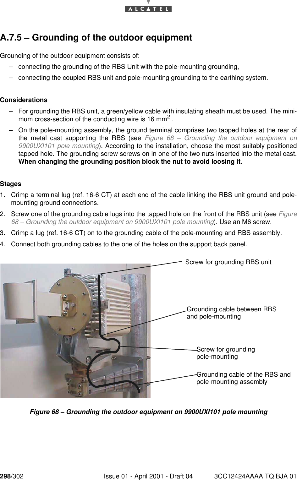
298/302 Issue 01 - April 2001 - Draft 04 3CC12424AAAA TQ BJA 01298A.7.5 – Grounding of the outdoor equipmentGrounding of the outdoor equipment consists of:–connecting the grounding of the RBS Unit with the pole-mounting grounding,–connecting the coupled RBS unit and pole-mounting grounding to the earthing system.Considerations–For grounding the RBS unit, a green/yellow cable with insulating sheath must be used. The mini-mum cross-section of the conducting wire is 16 mm2 .–On the pole-mounting assembly, the ground terminal comprises two tapped holes at the rear ofthe metal cast supporting the RBS (see Figure 68 – Grounding the outdoor equipment on9900UXI101 pole mounting). According to the installation, choose the most suitably positionedtapped hole. The grounding screw screws on in one of the two nuts inserted into the metal cast.When changing the grounding position block the nut to avoid loosing it.Stages1. Crimp a terminal lug (ref. 16-6 CT) at each end of the cable linking the RBS unit ground and pole-mounting ground connections.2. Screw one of the grounding cable lugs into the tapped hole on the front of the RBS unit (see Figure68 – Grounding the outdoor equipment on 9900UXI101 pole mounting). Use an M6 screw.3. Crimp a lug (ref. 16-6 CT) on to the grounding cable of the pole-mounting and RBS assembly.4. Connect both grounding cables to the one of the holes on the support back panel.Figure 68 – Grounding the outdoor equipment on 9900UXI101 pole mountingScrew for grounding RBS unitScrew for groundingGrounding cable between RBSand pole-mountingpole-mountingGrounding cable of the RBS andpole-mounting assembly
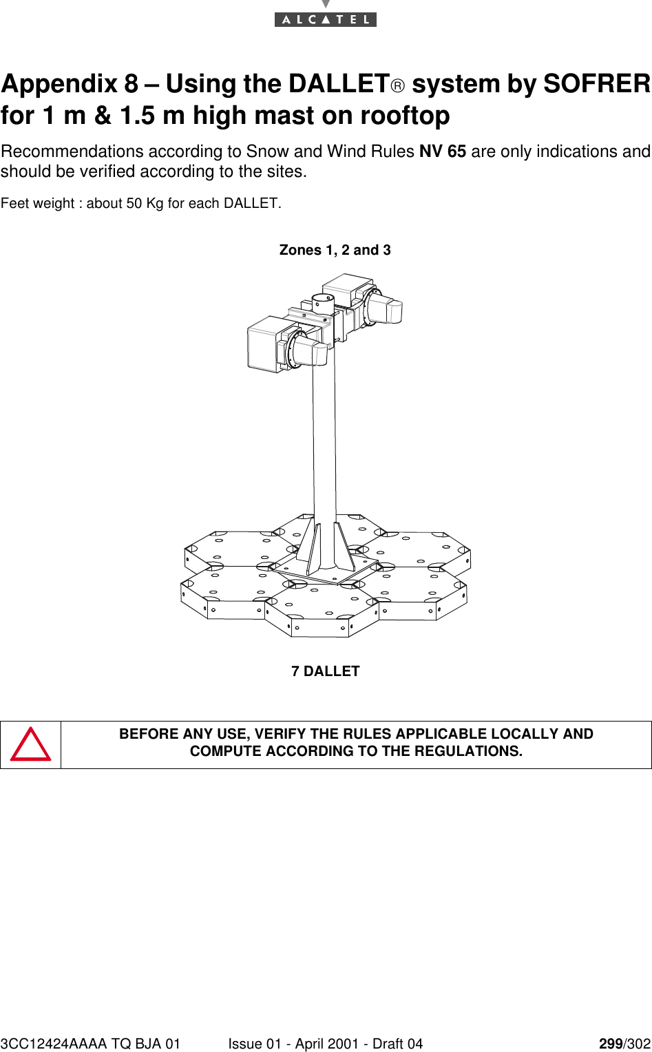
3CC12424AAAA TQ BJA 01 Issue 01 - April 2001 - Draft 04 299/302300Appendix 8 – Using the DALLET system by SOFRERfor 1 m & 1.5 m high mast on rooftopRecommendations according to Snow and Wind Rules NV 65 are only indications andshould be verified according to the sites.Feet weight : about 50 Kg for each DALLET.7 DALLETBEFORE ANY USE, VERIFY THE RULES APPLICABLE LOCALLY ANDCOMPUTE ACCORDING TO THE REGULATIONS.Zones 1, 2 and 3
300/302 Issue 01 - April 2001 - Draft 04 3CC12424AAAA TQ BJA 01300PAGE INTENTIONALLY LEFT BLANK
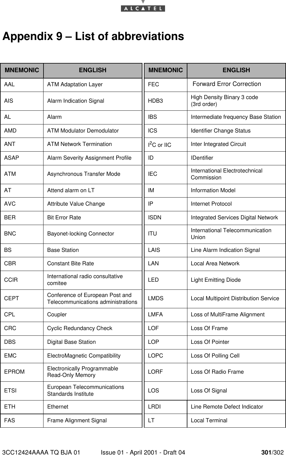
3CC12424AAAA TQ BJA 01 Issue 01 - April 2001 - Draft 04 301/302302Appendix 9 – List of abbreviationsMNEMONIC ENGLISH MNEMONIC ENGLISHAAL ATM Adaptation Layer FEC  Forward Error CorrectionAIS Alarm Indication Signal HDB3 High Density Binary 3 code(3rd order)AL Alarm IBS Intermediate frequency Base StationAMD ATM Modulator Demodulator ICS Identifier Change StatusANT ATM Network Termination I2C or IIC Inter Integrated CircuitASAP Alarm Severity Assignment Profile ID IDentifierATM Asynchronous Transfer Mode IEC International ElectrotechnicalCommissionAT Attend alarm on LT IM Information ModelAVC Attribute Value Change IP Internet ProtocolBER Bit Error Rate ISDN Integrated Services Digital NetworkBNC Bayonet-locking Connector ITU International Telecommunication UnionBS Base Station LAIS Line Alarm Indication SignalCBR Constant Bite Rate LAN Local Area NetworkCCIR International radio consultativecomitee LED Light Emitting DiodeCEPT Conference of European Post and Telecommunications administrations LMDS Local Multipoint Distribution ServiceCPL Coupler LMFA Loss of MultiFrame AlignmentCRC Cyclic Redundancy Check LOF Loss Of FrameDBS Digital Base Station LOP Loss Of PointerEMC ElectroMagnetic Compatibility LOPC Loss Of Polling CellEPROM Electronically ProgrammableRead-Only Memory LORF Loss Of Radio FrameETSI European Telecommunications Standards Institute LOS Loss Of SignalETH Ethernet LRDI Line Remote Defect IndicatorFAS Frame Alignment Signal LT Local Terminal
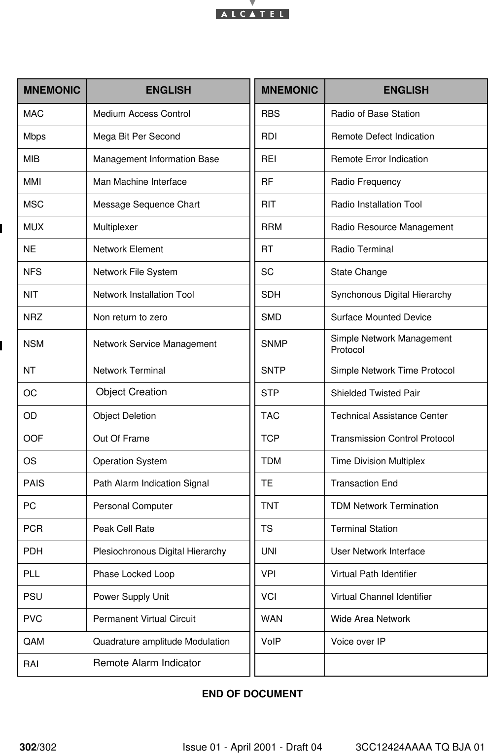
302/302 Issue 01 - April 2001 - Draft 04 3CC12424AAAA TQ BJA 01302END OF DOCUMENT MNEMONIC ENGLISH MNEMONIC ENGLISHMAC Medium Access Control RBS Radio of Base StationMbps Mega Bit Per Second RDI Remote Defect IndicationMIB Management Information Base REI Remote Error IndicationMMI  Man Machine Interface RF Radio FrequencyMSC Message Sequence Chart RIT Radio Installation ToolMUX Multiplexer RRM Radio Resource ManagementNE Network Element RT Radio TerminalNFS Network File System SC State ChangeNIT  Network Installation Tool SDH Synchonous Digital HierarchyNRZ  Non return to zero SMD Surface Mounted DeviceNSM  Network Service Management SNMP Simple Network ManagementProtocolNT Network Terminal SNTP Simple Network Time ProtocolOC  Object Creation STP Shielded Twisted PairOD Object Deletion TAC Technical Assistance CenterOOF Out Of Frame TCP Transmission Control ProtocolOS Operation System TDM Time Division MultiplexPAIS Path Alarm Indication Signal TE Transaction EndPC Personal Computer TNT TDM Network TerminationPCR Peak Cell Rate TS Terminal StationPDH Plesiochronous Digital Hierarchy UNI User Network InterfacePLL Phase Locked Loop VPI Virtual Path IdentifierPSU Power Supply Unit VCI Virtual Channel IdentifierPVC Permanent Virtual Circuit WAN Wide Area NetworkQAM Quadrature amplitude Modulation VoIP Voice over IPRAI Remote Alarm Indicator

Navigation menu