Alcatel Canada 24T28A01D22C 7390 24 GHz Co-Pol RBS User Manual BS Manual pages 277 to 280

Alcatel Canada Inc 7390 24 GHz Co-Pol RBS BS Manual pages 277 to 280

BS Manual pages 277 to 280

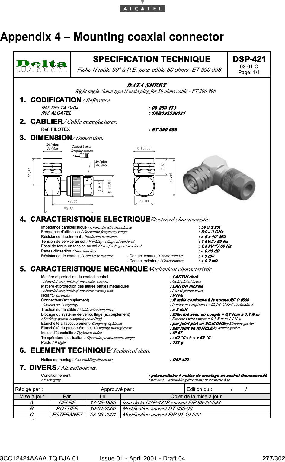
3CC12424AAAA TQ BJA 01 Issue 01 - April 2001 - Draft 04 277/302284 SPECIFICATION TECHNIQUE Fiche N mâle 90° à P.E. pour câble 50 ohms - ET 390 998 DSP-421 03-01-C Page: 1/1   Rédigé par :  Approuvé par :   Edition du :             /         /      Mise à jour  Par  Le  Objet de la mise à jour A  DELRE  17-09-1998  Issu de la DSP-421P suivant FIP 98-38-093 B  POTTIER  10-04-2000  Modification suivant DT 033-00 C  ESTEBANEZ  08-03-2001  Modification suivant FIP 01-10-022 DATA SHEET Right angle clamp type N male plug for 50 ohms cable - ET 390 998  1.  CODIFICATION / Reference. Réf. DELTA OHM  : 08 250 173 Réf. ALCATEL  : 1AB095530021 2.  CABLIER / Cable manufacturer. Ref. FILOTEX : ET 390 998 3.  DIMENSION / Dimension. 20 / plats20 / flats20 / plats20 / flatsContact à sertirCrimping contact 4.  CARACTERISTIQUE ELECTRIQUE / Electrical characteristic. Impédance caractéristique / Characteristic impedance : 50 ΩΩ ± 2% Fréquence d'utilisation / Operating frequency range : DC – 3 GHz Résistance d'isolement / Insulation resistance : ≥≥ 5 x 10³³ MΩΩ Tension de service au sol / Working voltage at sea level : 1 kVeff / 50 Hz Essai de tenue en tension au sol / Proof voltage at sea level : 1.5 kVeff / 50 Hz Pertes d'insertion / Insertion loss : ≤≤ 0.05 dB Résistance de contact / Contact resistance - Contact central / Center contact  : ≤≤ 1 mΩΩ   - Contact extérieur / Outer contact : ≤≤ 0.2 mΩΩ 5.  CARACTERISTIQUE MECANIQUE / Mechanical characteristic. Matière et protection du contact central : LAITON doré / Material and finish of the center contact  : Gold plated brass Matière et protection des autres parties métalliques : LAITON nickelé / Material and finish of the other metal parts  : Nickel plated brass Isolant / Insulator : PTFE Connecteur (accouplement) : N mâle conforme à la norme NF C 93-566 / Connector (coupling) : N male in compliance with NF C 93-566 standard Traction sur le câble / Cable retention force : ≥≥ 2 daN Blocage du système de verrouillage (accouplement) : Effectué avec un couple = 0,7 N.m à 1,1 N.m / Locking system clamping (coupling)  : Executed with torque = 0.7 N.m to 1.1 N.m Etanchéité à l'accouplement / Coupling tightness : par joint plat en SILICONE / by Silicone gasket Etanchéité du presse-étoupe / Clamping nut tightness : par joint en NITRILE / by Nitrile gasket Indice d'étanchéité / Tightness index : IP 67 Température d'utilisation / Operating temperature range : - 40 °C << θθ << + 65 °C Poids / Weight : 133 g 6.  ELEMENT TECHNIQUE / Technical data. Notice de montage / Assembling directions : DSP-422 7.  DIVERS / Miscellaneous. Conditionnement : pièce unitaire + notice de montage en sachet thermosoudé / Packaging  : per unit + assembling directions in hermetic bag Appendix 4 – Mounting coaxial connector
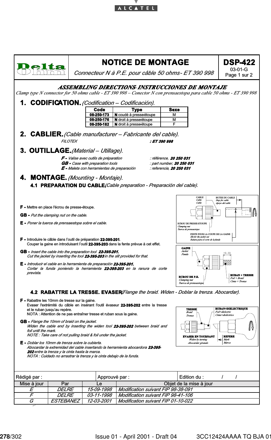
278/302 Issue 01 - April 2001 - Draft 04 3CC12424AAAA TQ BJA 01284 NOTICE DE MONTAGE Connecteur N à P.E. pour câble 50 ohms - ET 390 998 DSP-422 03-01-G Page 1 sur 2   Rédigé par :  Approuvé par :   Edition du :             /         /      Mise à jour  Par  Le  Objet de la mise à jour E  DELRE  15-09-1998  Modification suivant FIP 98-38-091 F  DELRE  03-11-1998  Modification suivant FIP 98-41-106 G  ESTEBANEZ  12-03-2001  Modification suivant FIP 01-10-022 ASSEMBLING DIRECTIONS – INSTRUCCIONES DE MONTAJE Clamp type N connector for 50 ohms cable - ET 390 998 – Conector N con prensaestopa para cable 50 ohms - ET 390 998 1.  CODIFICATION. (Codification – Codificación). Code  Type  Sexe 08-250-173  N coudé à presse-étoupe  M 08-250-176  N droit à presse-étoupe  M 08-250-182  N droit à presse-étoupe  F 2.  CABLIER. (Cable manufacturer – Fabricante del cable). FILOTEX  : ET 390 998 3.  OUTILLAGE. (Material – Utillage). F - Valise avec outils de préparation  : référence, 20 250 031 GB - Case with preparation tools  : part number, 20 250 031 E - Maleta con herramientas de preparación  : referencia, 20 250 031 4.  MONTAGE. (Mounting - Montaje). 4.1  PREPARATION DU CABLE. (Cable preparation - Preparación del cable).  F - Mettre en place l'écrou de presse-étoupe. GB - Put the clamping nut on the cable. E - Poner la tuerca de prensaestopa sobre el cable. F -  Introduire le câble dans l’outil de préparation 22-395-201. Couper la gaine en introduisant l’outil 22-395-203 dans la fente prévue à cet effet. GB - Insert the cable into the preparation tool  22-395-201. Cut the jacket by inserting the tool 22-395-203 in the slit provided for that. E - Introducir el cable en la herramienta de preparación 22-395-201. Cortar  la  funda  poniendo  la  herramienta  22-395-203  en  la  ranura  de  corte prevista.  BUTEE DU CABLEStop for cableApoyo del cableCABLECableCableFENTE POUR LA COUPE DE LA GAINESlit for the jacket cutRanura para el corte de la fundaECROU DE PRESSE-ETOUPEClamping nutTuerca de prensaestopa  RUBAN + TRESSEFoil + BraidCinta + TrenzaGAINEJacketFundaECROU DE P.E.Clamping nutTuerca de prensaestopa4.2  RABATTRE LA TRESSE. EVASER. (Flange the braid. Widen - Doblar la trenza. Abocardar).  F - Rabattre les 10mm de tresse sur la gaine. Evaser  l'extrémité  du  câble  en  insérant  l'outil  évaseur  22-395-202  entre  la  tresse et le ruban jusqu’au repère. NOTA : Attention de ne pas entraîner tresse et ruban sous la gaine. GB - Flange the 10mm of braid on the jacket. Widen  the  cable  end  by  inserting  the  widen  tool  22-395-202  between  braid  and foil until the mark. NOTE : Take care of not pulling braid & foil under the jacket. E - Doblar los 10mm de trenza sobre la cubierta. Abocardar la extremidad del cable insertando la herramienta abocardora 22-395-202 entre la trenza y la cinta hasta la marca. NOTA : Cuidado no arrastrar la trenza y la cinta debajo de la funda. EVASER EN TOURNANTWiden by turningAbocardar girandoRUBAN+DIELECTRIQUEFoil+dielectricCinta+dieléctricoREPEREMarkMarcaTRESSEBraidTrenza
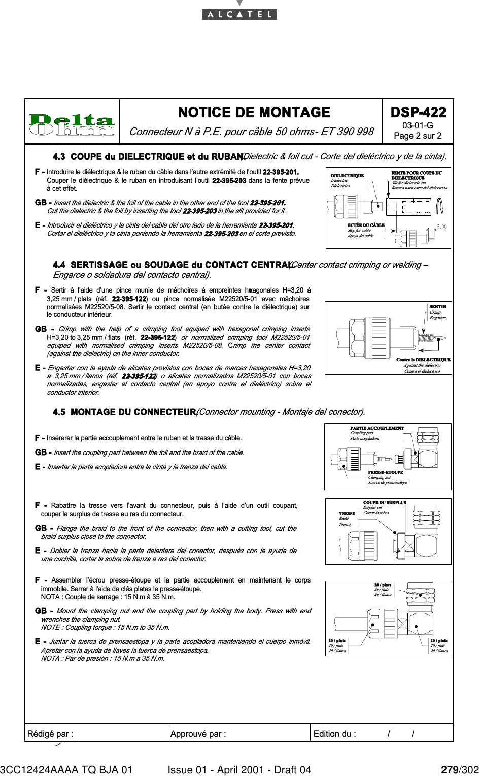
3CC12424AAAA TQ BJA 01 Issue 01 - April 2001 - Draft 04 279/302284 NOTICE DE MONTAGE Connecteur N à P.E. pour câble 50 ohms - ET 390 998 DSP-422 03-01-G Page 2 sur 2   Rédigé par :  Approuvé par :   Edition du :             /         /      4.3  COUPE du DIELECTRIQUE et du RUBAN. (Dielectric & foil cut - Corte del dieléctrico y de la cinta). F - Introduire le diélectrique & le ruban du câble dans l’autre extrémité de l’outil 22-395-201. Couper  le  diélectrique  &  le  ruban  en  introduisant  l’outil  22-395-203  dans  la  fente  prévue à cet effet. GB - Insert the dielectric & the foil of the cable in the other end of the tool 22-395-201. Cut the dielectric & the foil by inserting the tool 22-395-203 in the slit provided for it. E - Introducir el dieléctrico y la cinta del cable del otro lado de la herramienta 22-395-201. Cortar el dieléctrico y la cinta poniendo la herramienta 22-395-203 en el corte previsto. FENTE POUR COUPE DUDIELECTRIQUESlit for dielectric cutRanura para corte del dielectricoBUTÉE DU CÂBLEStop for cableApoyo del cableDIELECTRIQUEDielectricDieléctrico 4.4  SERTISSAGE ou SOUDAGE du CONTACT CENTRAL. (Center contact crimping or welding – Engarce o soldadura del contacto central). F  -  Sertir  à  l’aide  d’une  pince  munie  de  mâchoires  à  empreintes  hexagonales  H=3,20  à 3,25 mm / plats  (réf.  22-395-122)  ou  pince  normalisée  M22520/5-01  avec  mâchoires normalisées  M22520/5-08.  Sertir  le  contact  central  (en  butée  contre  le  diélectrique)  sur le conducteur intérieur. GB  - Crimp  with  the  help  of  a  crimping  tool  equiped  with  hexagonal  crimping  inserts H=3,20 to 3,25 mm / flats  (réf.  22-395-122) or  normalized  crimping  tool  M22520/5-01 equiped  with  normalised  crimping  inserts  M22520/5-08.  Crimp  the  center  contact (against the dielectric) on the inner conductor. E - Engastar con la  ayuda  de alicates provistos con  bocas  de marcas hexagonales H=3,20 a  3,25 mm / llanos  (réf.  22-395-122)  o  alicates  normalizados  M22520/5-01  con  bocas normalizadas,  engastar  el  contacto  central  (en  apoyo  contra  el  dieléctrico)  sobre  el conductor interior. Contre le DIELECTRIQUEAgainst the dielectricContra el dielectricoSERTIRCrimpEngastar 4.5  MONTAGE DU CONNECTEUR. (Connector mounting - Montaje del conector). F - Insérerer la partie accouplement entre le ruban et la tresse du câble.  GB - Insert the coupling part between the foil and the braid of the cable.  E - Insertar la parte acopladora entre la cinta y la trenza del cable.  PRESSE-ETOUPEClamping nutTuerca de prensaestopaPARTIE ACCOUPLEMENTCoupling partParte acopladora F  -  Rabattre  la  tresse  vers  l’avant  du  connecteur,  puis  à  l’aide  d’un  outil  coupant, couper le surplus de tresse au ras du connecteur. GB  - Flange  the  braid  to  the  front  of  the  connector,  then  with  a  cutting  tool,  cut  the braid surplus close to the connector.  E  - Doblar  la  trenza  hacia  la  parte  delantera  del  conector,  después  con  la  ayuda  de una cuchilla, cortar la sobra de trenza a ras del conector. COUPE DU SURPLUSSurplus cutCortar la sobraTRESSEBraidTrenza F  -  Assembler  l’écrou  presse-étoupe  et  la  partie  accouplement  en  maintenant  le  corps immobile. Serrer à l'aide de clés plates le presse-étoupe. NOTA : Couple de serrage : 15 N.m à 35 N.m. GB  - Mount  the  clamping  nut  and  the  coupling  part  by  holding  the  body.  Press  with  end wrenches the clamping nut. NOTE : Coupling torque : 15 N.m to 35 N.m.  E  - Juntar  la  tuerca  de  prensaestopa  y  la  parte  acopladora  manteniendo  el  cuerpo  inmóvil. Apretar con la ayuda de llaves la tuerca de prensaestopa.  NOTA : Par de presión : 15 N.m a 35 N.m.  20 / plats20 / flats20 / llanos20 / plats20 / flats20 / llanos20 / plats20 / flats20 / llanos
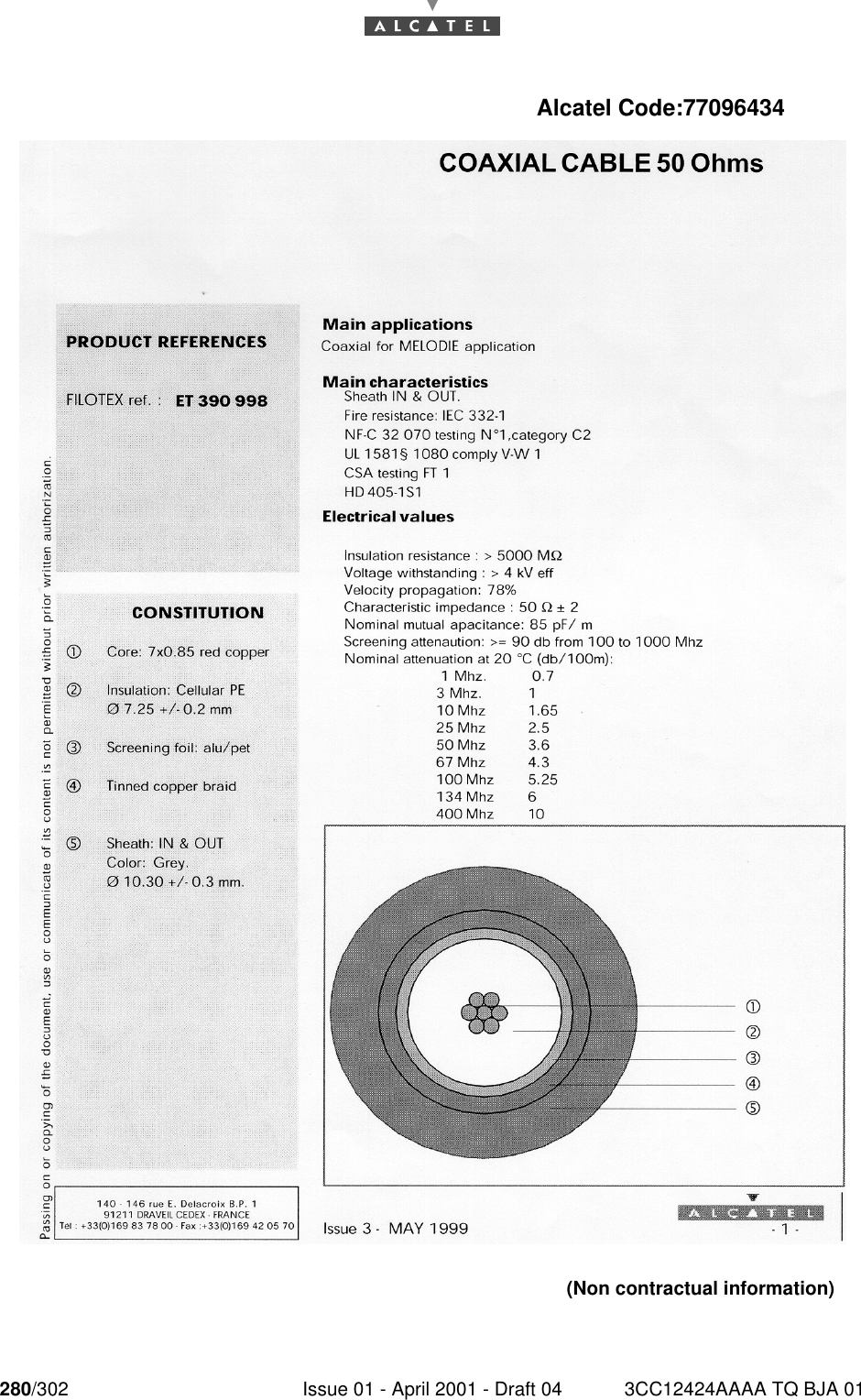
280/302 Issue 01 - April 2001 - Draft 04 3CC12424AAAA TQ BJA 01284Alcatel Code:77096434(Non contractual information)

Navigation menu