Alarm com orporated 143IS205V4 wireless transceiver that operates in the amateur band, 902 – 928 MHz User Manual Alarm com User Guide

Alarm.com Incorporated wireless transceiver that operates in the amateur band, 902 – 928 MHz Alarm com User Guide

User Guide
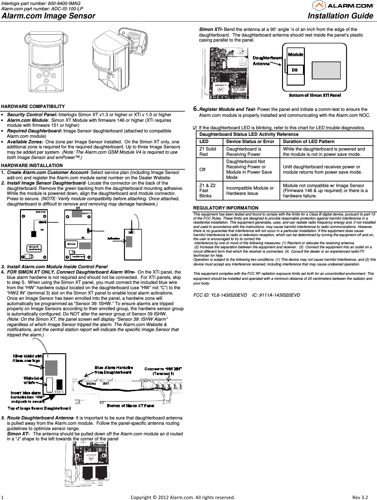
Interlogix part number: 600-9400-IMAG Alarm.com part number: ADC-IS-100-LP Alarm.com Image Sensor  1                                                                                                            Copy                                       HARDWARE COMPATIBILITY  • Security Control Panel: Interlogix Simon XT v1.3 or higher or XTi v 1.0 or higher• Alarm.com Module:  Simon XT Module with firmware 146 or highermodule with firmware 151 or higher) • Required Daughterboard: Image Sensor daughterboard (attacheAlarm.com module) • Available Zones:  One zone per Image Sensor installed.  On the Simon XT only, one additional zone is required for the required daughterboard. Up to three Image Sensors may be added per system. (Note: The Alarm.com GSM Module V4both Image Sensor and emPower™.)  HARDWARE INSTALLATION 1.  Create Alarm.com Customer Account- Select service plan (including Image Sensor add-on) and register the Alarm.com module serial number on the Dealer 2.  Install Image Sensor Daughterboard- Locate the connector on the back of the daughterboard. Remove the green backing from the daughterboard mounting adhesive.  While the module is powered down, align the daughterboard and module Press to secure. (NOTE: Verify module compatibility before attachingdaughterboard is difficult to remove and removing may damage hardware.           3.  Install Alarm.com Module Inside Control Panel 4.  FOR SIMON XT ONLY, Connect Daughterboard Alarm Wire-  On the XTi panel, the blue alarm hardwire is not required and should not be connected.  to step 5.  When using the Simon XT panel, you must connect the from the “HW” hardwire output located on the daughterboard (use “HW” not “C”)“HW2 IN” (terminal 3) slot on the Simon XT panel to enable local alarm activationsOnce an Image Sensor has been enrolled into the panel, a hardwire zone will automatically be programmed as “Sensor 39: ISHW.” To ensure alarms are tripped properly on Image Sensors according to their enrolled group, the hardwire sensor group is automatically configured. Do NOT alter the sensor group of Sensor 39 ISHW(Note: On the Simon XT, the panel screen will display “Sensor 39: ISregardless of which Image Sensor tripped the alarm. The Alarm.com notifications, and the central station report will indicate the specific Image Sensor that tripped the alarm.)  5.  Route Daughterboard Antenna- It is important to be sure that daughterboard antenna is pulled away from the Alarm.com module.  Follow the panel-specific antenna routing guidelines to optimize sensor range.   Simon XT-   The antenna should be pulled down off the Alarm.com modulein a “J” shape to the left towards the corner of the panel                                             opyright © 2012 Alarm.com. All rights reserved.    XTi v 1.0 or higher higher (XTi requires attached to compatible d.  On the Simon XT only, one Up to three Image Sensors V4 is required to use Select service plan (including Image Sensor the Dealer Website.  Locate the connector on the back of the daughterboard. Remove the green backing from the daughterboard mounting adhesive.  and module connector.  attaching. Once attached, daughterboard is difficult to remove and removing may damage hardware.) On the XTi panel, the    For XTi panels, skip you must connect the included blue wire (use “HW” not “C”) to the to enable local alarm activations. Image Sensor has been enrolled into the panel, a hardwire zone will To ensure alarms are tripped rolled group, the hardwire sensor group Do NOT alter the sensor group of Sensor 39 ISHW. een will display “Sensor 39: ISHW Alarm” The Alarm.com Website & and the central station report will indicate the specific Image Sensor that  It is important to be sure that daughterboard antenna specific antenna routing The antenna should be pulled down off the Alarm.com module an d routed Simon XTi- Bend the antenna at a 90° angle ¼ of an inch from thedaughterboard.  The daughterboard antenna casing parallel to the panel.   6. Register Module and Test- Power the panel and initiate a Alarm.com module is properly installed and communicating with the Alarm.com   If the daughterboard LED is blinking, refer to Daughterboard Status LED Activity ReferenceLED   Device Status or Error  Duration of LED PatternZ1 Solid Red  Daughterboard is  Receiving Power While the daughterboard is poweredthe module is not in power save modeOff  Daughterboard Not Receiving Power or Module in Power Save Mode Until daughterboard receivmodule returns from power save mode. Z1 & Z2 Fast Blinks  Incompatible Module or Hardware Issue  Module not compatible w/ Image Sensor (Firmware 146 &hardware failure.  REGULATORY INFORMATION This equipment has been tested and found to comply with the limits for a Class B digital device, pursuant to part 15 of the FCC Rules. These limits are designed to provide reasonable protection against harmful interference in a residential installation. This equipment generates, uses, and can radiate radio frequency energy and, if not installed and used in accordance with the instructions, may cause harmful interference to radio communications. However, there is no guarantee that interference will not occur in a particular installation. If this equipment does cause harmful interference to radio or television reception, which can be determined by turning the equipment off and on, the user is encouraged to try to correct the  interference by one or more of the following measures: (1) Reorient or relocate the receiving antenna. (2) Increase the separation between the equipment and receiver.  (3)  Connect the equipment into an outlet on a circuit different form that which the receiver is connected. (4)  Consult the dealer or an experienced radio/TV technician for help. Operation is subject to the following two conditions: (1) This device may not cause harmful interference, and (2) this device must accept any interference received, including interference that may cause undesired operation. This equipment complies with the FCC RF radiation exposure limits set forth for an uncontrolled environment. This equipment should be installed and operated with a minimum distance of 20 centimeters between the radiator and your body. FCC ID: YL6-143IS20EVD    IC: 9111A-143IS2   Installation Guide                        Rev 3.2  angle ¼ of an inch from the edge of the antenna should rest inside the panel’s plastic  the panel and initiate a comm-test to ensure the odule is properly installed and communicating with the Alarm.com NOC.  f the daughterboard LED is blinking, refer to this chart for LED trouble diagnostics. Daughterboard Status LED Activity Reference  Duration of LED Pattern  While the daughterboard is powered and the module is not in power save mode. Until daughterboard receives power or module returns from power save mode.  odule not compatible w/ Image Sensor (Firmware 146 & up required) or there is a hardware failure.  This equipment has been tested and found to comply with the limits for a Class B digital device, pursuant to part 15 of the FCC Rules. These limits are designed to provide reasonable protection against harmful interference in a ential installation. This equipment generates, uses, and can radiate radio frequency energy and, if not installed and used in accordance with the instructions, may cause harmful interference to radio communications. However, rference will not occur in a particular installation. If this equipment does cause harmful interference to radio or television reception, which can be determined by turning the equipment off and on, ce by one or more of the following measures: (1) Reorient or relocate the receiving antenna. Increase the separation between the equipment and receiver.  (3)  Connect the equipment into an outlet on a connected. (4)  Consult the dealer or an experienced radio/TV Operation is subject to the following two conditions: (1) This device may not cause harmful interference, and (2) this g interference that may cause undesired operation. This equipment complies with the FCC RF radiation exposure limits set forth for an uncontrolled environment. This inimum distance of 20 centimeters between the radiator and 20EVD

Navigation menu