Alarm com orporated 143100ISGC This unit is a wireless transceiver that operates in the amateur band 902-928MHz User Manual User Guide

Alarm.com Incorporated This unit is a wireless transceiver that operates in the amateur band 902-928MHz User Guide

User Manual
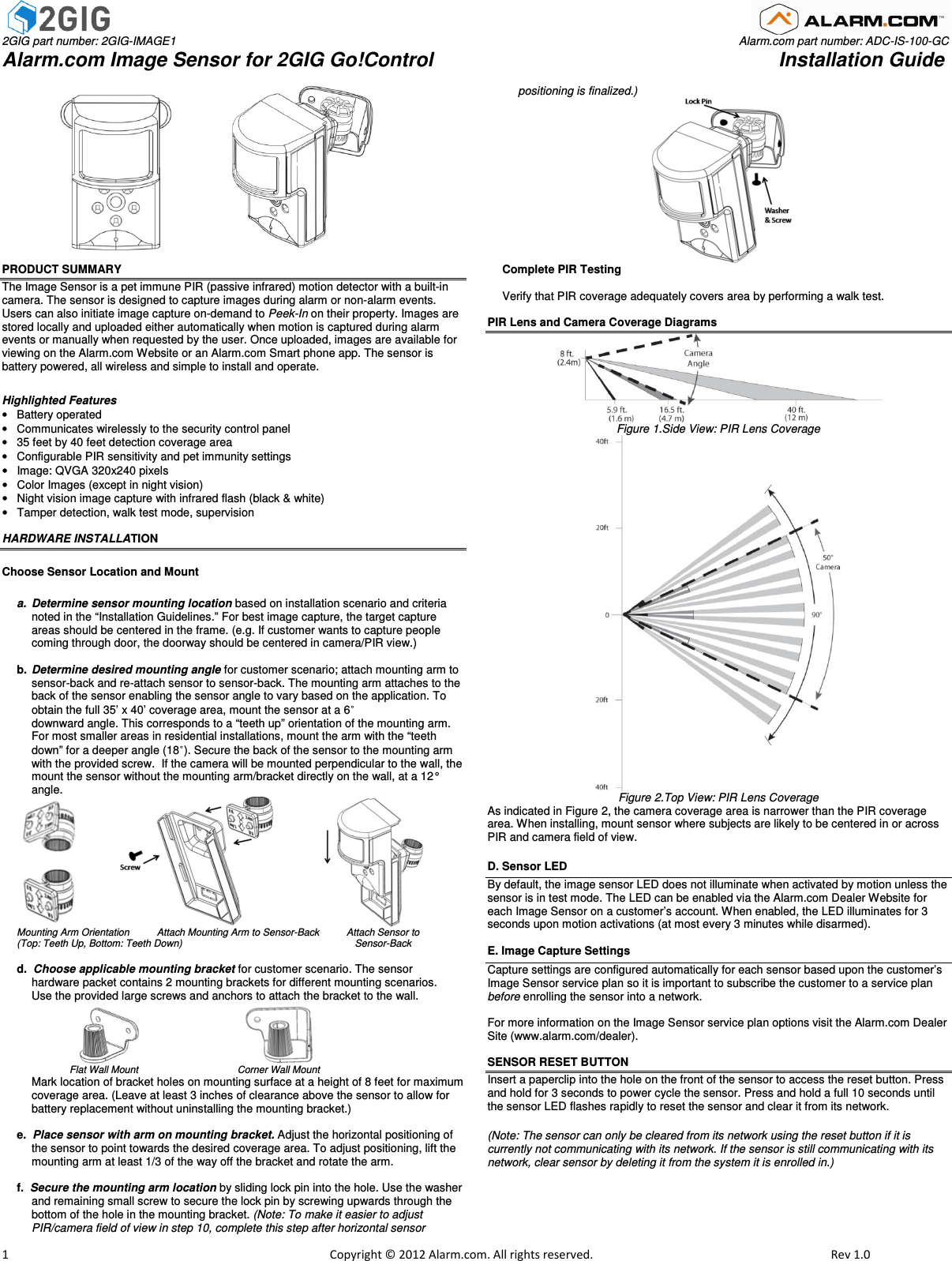
 2GIG part number: 2GIG-IMAGE1                                                                                                                                                                                Alarm.com part number: ADC-IS-100-GC Alarm.com Image Sensor for 2GIG Go!Control                                                               Installation Guide                         1                                                                                                            Copyright © 2012 Alarm.com. All rights reserved.     Rev 1.0                                     PRODUCT SUMMARY The Image Sensor is a pet immune PIR (passive infrared) motion detector with a built-in camera. The sensor is designed to capture images during alarm or non-alarm events. Users can also initiate image capture on-demand to Peek-In on their property. Images are stored locally and uploaded either automatically when motion is captured during alarm events or manually when requested by the user. Once uploaded, images are available for viewing on the Alarm.com Website or an Alarm.com Smart phone app. The sensor is battery powered, all wireless and simple to install and operate.    Highlighted Features •  Battery operated  •  Communicates wirelessly to the security control panel •  35 feet by 40 feet detection coverage area •  Configurable PIR sensitivity and pet immunity settings  •  Image: QVGA 320x240 pixels  •  Color Images (except in night vision) •  Night vision image capture with infrared flash (black & white) •  Tamper detection, walk test mode, supervision  HARDWARE INSTALLATION  Choose Sensor Location and Mount  a.  Determine sensor mounting location based on installation scenario and criteria noted in the “Installation Guidelines.” For best image capture, the target capture areas should be centered in the frame. (e.g. If customer wants to capture people coming through door, the doorway should be centered in camera/PIR view.)  b.  Determine desired mounting angle for customer scenario; attach mounting arm to sensor-back and re-attach sensor to sensor-back. The mounting arm attaches to the back of the sensor enabling the sensor angle to vary based on the application. To obtain the full 35’ x 40’ coverage area, mount the sensor at a 6˚  downward angle. This corresponds to a “teeth up” orientation of the mounting arm.  For most smaller areas in residential installations, mount the arm with the “teeth down” for a deeper angle (18˚). Secure the back of the sensor to the mounting arm with the provided screw.  If the camera will be mounted perpendicular to the wall, the mount the sensor without the mounting arm/bracket directly on the wall, at a 12° angle.                             Mounting Arm Orientation          Attach Mounting Arm to Sensor-Back          Attach Sensor to  (Top: Teeth Up, Bottom: Teeth Down)                                                               Sensor-Back  d.  Choose applicable mounting bracket for customer scenario. The sensor  hardware packet contains 2 mounting brackets for different mounting scenarios.  Use the provided large screws and anchors to attach the bracket to the wall.                                                                                Flat Wall Mount                       Corner Wall Mount  Mark location of bracket holes on mounting surface at a height of 8 feet for maximum coverage area. (Leave at least 3 inches of clearance above the sensor to allow for battery replacement without uninstalling the mounting bracket.)    e.  Place sensor with arm on mounting bracket. Adjust the horizontal positioning of the sensor to point towards the desired coverage area. To adjust positioning, lift the mounting arm at least 1/3 of the way off the bracket and rotate the arm.  f.  Secure the mounting arm location by sliding lock pin into the hole. Use the washer and remaining small screw to secure the lock pin by screwing upwards through the bottom of the hole in the mounting bracket. (Note: To make it easier to adjust PIR/camera field of view in step 10, complete this step after horizontal sensor       positioning is finalized.)                                                    Complete PIR Testing   Verify that PIR coverage adequately covers area by performing a walk test.  PIR Lens and Camera Coverage Diagrams  Figure 1.Side View: PIR Lens Coverage  Figure 2.Top View: PIR Lens Coverage  As indicated in Figure 2, the camera coverage area is narrower than the PIR coverage area. When installing, mount sensor where subjects are likely to be centered in or across PIR and camera field of view. D. Sensor LED By default, the image sensor LED does not illuminate when activated by motion unless the sensor is in test mode. The LED can be enabled via the Alarm.com Dealer Website for each Image Sensor on a customer’s account. When enabled, the LED illuminates for 3 seconds upon motion activations (at most every 3 minutes while disarmed).  E. Image Capture Settings Capture settings are configured automatically for each sensor based upon the customer’s Image Sensor service plan so it is important to subscribe the customer to a service plan before enrolling the sensor into a network.    For more information on the Image Sensor service plan options visit the Alarm.com Dealer Site (www.alarm.com/dealer).  SENSOR RESET BUTTON  Insert a paperclip into the hole on the front of the sensor to access the reset button. Press and hold for 3 seconds to power cycle the sensor. Press and hold a full 10 seconds until the sensor LED flashes rapidly to reset the sensor and clear it from its network.  (Note: The sensor can only be cleared from its network using the reset button if it is currently not communicating with its network. If the sensor is still communicating with its network, clear sensor by deleting it from the system it is enrolled in.)
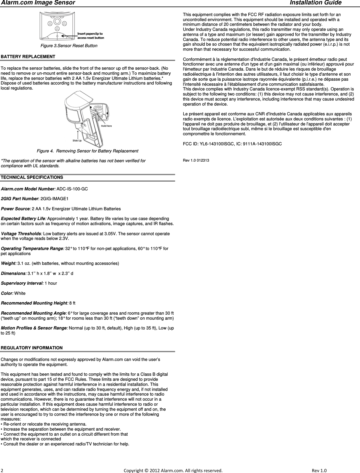
Alarm.com Image Sensor     Installation Guide     2                                                                                                            Copyright © 2012 Alarm.com. All rights reserved.     Rev 1.0                                                              Figure 3.Sensor Reset Button BATTERY REPLACEMENT  To replace the sensor batteries, slide the front of the sensor up off the sensor-back. (No need to remove or un-mount entire sensor-back and mounting arm.) To maximize battery life, replace the sensor batteries with 2 AA 1.5v Energizer Ultimate Lithium batteries.* Dispose of used batteries according to the battery manufacturer instructions and following local regulations.  Figure 4.  Removing Sensor for Battery Replacement  *The operation of the sensor with alkaline batteries has not been verified for  compliance with UL standards.                                 TECHNICAL SPECIFICATIONS  Alarm.com Model Number: ADC-IS-100-GC  2GIG Part Number: 2GIG-IMAGE1  Power Source: 2 AA 1.5v Energizer Ultimate Lithium Batteries  Expected Battery Life: Approximately 1 year. Battery life varies by use case depending on certain factors such as frequency of motion activations, image captures, and IR flashes.  Voltage Thresholds: Low battery alerts are issued at 3.05V. The sensor cannot operate when the voltage reads below 2.3V.  Operating Temperature Range: 32° to 110°F for non-pet applications, 60° to 110°F for pet applications  Weight: 3.1 oz. (with batteries, without mounting accessories)  Dimensions: 3.1’’ h x 1.8’’ w  x 2.3’’ d  Supervisory Interval: 1 hour  Color: White  Recommended Mounting Height: 8 ft   Recommended Mounting Angle: 6° for large coverage area and rooms greater than 30 ft (“teeth up” on mounting arm); 18° for rooms less than 30 ft (“teeth down” on mounting arm)  Motion Profiles & Sensor Range: Normal (up to 30 ft, default), High (up to 35 ft), Low (up to 25 ft)                                   REGULATORY INFORMATION  Changes or modifications not expressly approved by Alarm.com can void the user’s authority to operate the equipment.  This equipment has been tested and found to comply with the limits for a Class B digital device, pursuant to part 15 of the FCC Rules. These limits are designed to provide reasonable protection against harmful interference in a residential installation. This equipment generates, uses, and can radiate radio frequency energy and, if not installed and used in accordance with the instructions, may cause harmful interference to radio communications. However, there is no guarantee that interference will not occur in a particular installation. If this equipment does cause harmful interference to radio or television reception, which can be determined by turning the equipment off and on, the user is encouraged to try to correct the interference by one or more of the following measures: • Re-orient or relocate the receiving antenna. • Increase the separation between the equipment and receiver. • Connect the equipment to an outlet on a circuit different from that which the receiver is connected • Consult the dealer or an experienced radio/TV technician for help.  This equipment complies with the FCC RF radiation exposure limits set forth for an uncontrolled environment. This equipment should be installed and operated with a minimum distance of 20 centimeters between the radiator and your body. Under Industry Canada regulations, this radio transmitter may only operate using an antenna of a type and maximum (or lesser) gain approved for the transmitter by Industry Canada. To reduce potential radio interference to other users, the antenna type and its gain should be so chosen that the equivalent isotropically radiated power (e.i.r.p.) is not more than that necessary for successful communication.  Conformément à la réglementation d'Industrie Canada, le présent émetteur radio peut fonctionner avec une antenne d'un type et d'un gain maximal (ou inférieur) approuvé pour l'émetteur par Industrie Canada. Dans le but de réduire les risques de brouillage radioélectrique à l'intention des autres utilisateurs, il faut choisir le type d'antenne et son gain de sorte que la puissance isotrope rayonnée équivalente (p.i.r.e.) ne dépasse pas l'intensité nécessaire à l'établissement d'une communication satisfaisante. This device complies with Industry Canada licence-exempt RSS standard(s). Operation is subject to the following two conditions: (1) this device may not cause interference, and (2) this device must accept any interference, including interference that may cause undesired operation of the device.  Le présent appareil est conforme aux CNR d'Industrie Canada applicables aux appareils radio exempts de licence. L'exploitation est autorisée aux deux conditions suivantes : (1) l'appareil ne doit pas produire de brouillage, et (2) l'utilisateur de l'appareil doit accepter tout brouillage radioélectrique subi, même si le brouillage est susceptible d'en compromettre le fonctionnement.  FCC ID: YL6-143100ISGC, IC: 9111A-143100ISGC  Rev 1.0 012313

Navigation menu