Airspan Communications STODU-PCS Subscriber Terminal User Manual 605 0000 595 ST Installation and Commissioning
Airspan Communications Limited Subscriber Terminal 605 0000 595 ST Installation and Commissioning
UserManual.wiki
>
Airspan Communications
>
STODU PCS User Manual
User Manual
Navigation menu
Upload a User Manual
Namespaces
Wiki Guide
HTML
PDF
Info
Views
User Manual
Discussion / Help
Navigation

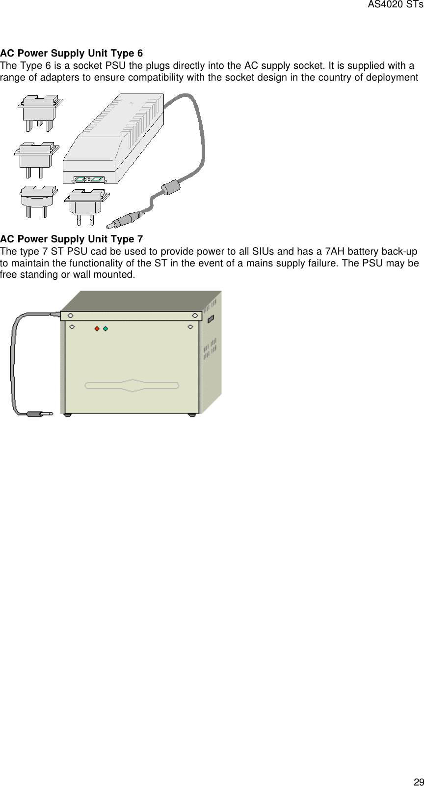
![605-0000-595 Subscriber Terminal Installation and Commissioning 32 • The ST Indoor Unit (IDU) is band/frequency independent for the Radio Link. This allows changing IDU ST operation frequency at any time by simple reprogramming using STMON or sometimes only by changing parameters of target shelf with AS8100 [see Frequency Agility in AS8100 Sitespan help file].](https://usermanual.wiki/Airspan-Communications/STODU-PCS/User-Guide-446538-Page-14.png)
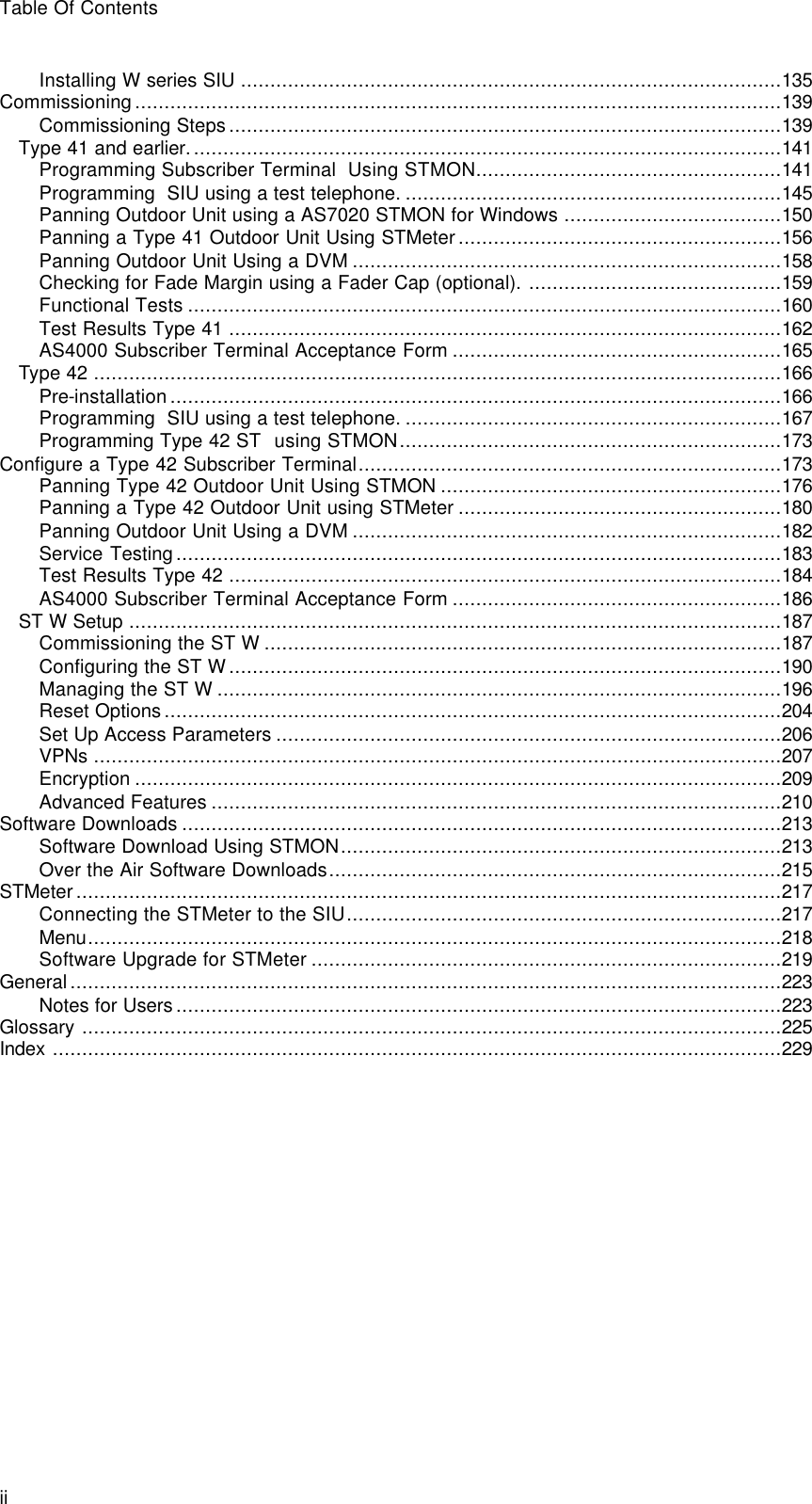
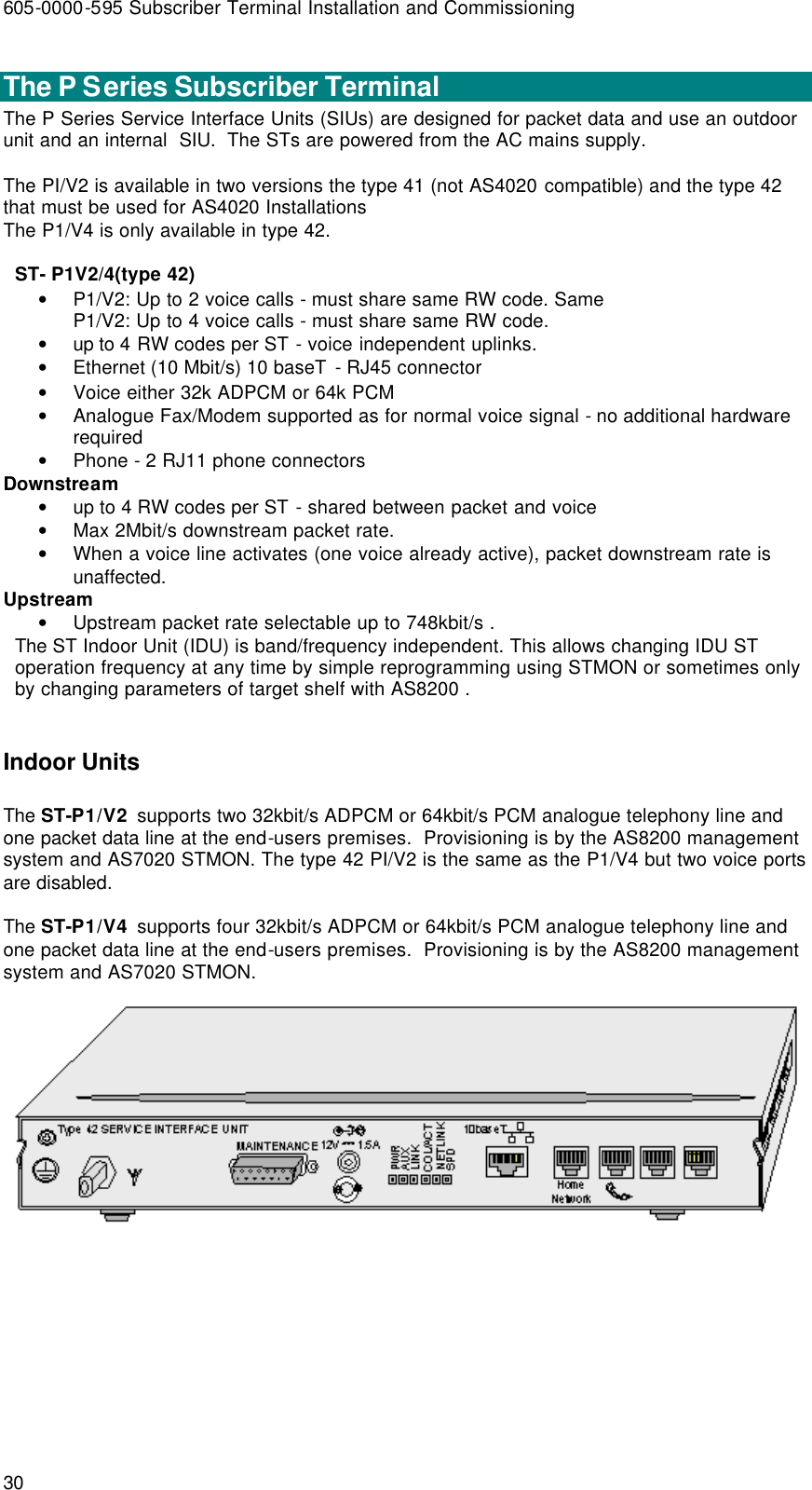
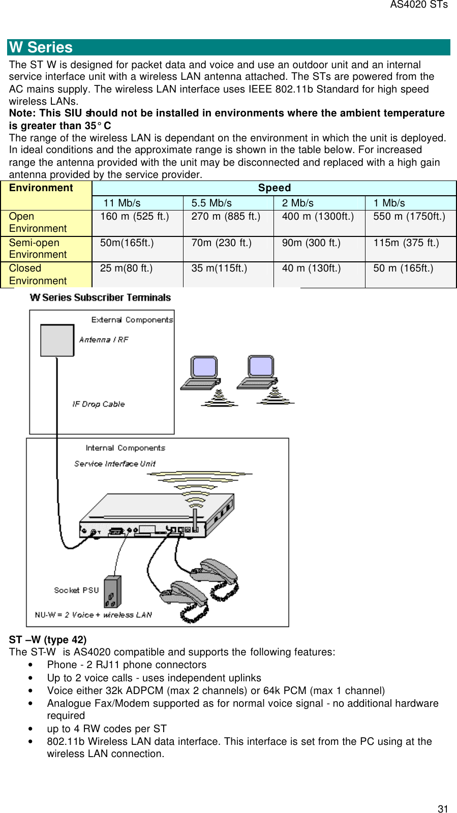
![AS4020 STs 33 V Series The V Series Service Interface Units are designed for Voice and use an outdoor unit and an internal Service Interface Unit. The STs are powered from the AC mains supply. ST –V2 (type 42) The ST-V4 is AS4020 compatible and supports the following features: • Phone - 2RJ11 phone connectors • Up to 2 voice calls - uses independent uplinks • Voice either 32k ADPCM (max 2 channels) or 64k PCM (max 1 channel) • Analogue Fax/Modem supported as for normal voice signal - no additional hardware required • up to 2 RW codes per ST • The ST Indoor Unit (IDU) is band/frequency independent. This allows changing IDU ST operation frequency at any time by simple reprogramming using STMON or sometimes only by changing parameters of target shelf with AS8100 [see Frequency Agility in AS8100 Sitespan help file]. The type 42 ST is compatible with Release 7.0 Sitespan code and with Release 6.20 rack code or later. • two voice ports and the 10baseT port is not enabled on this product. ST –V4 (type 42) The ST-V4 is AS4020 compatible and supports the following features: • Phone - 4 RJ11 phone connectors • Up to 4 voice calls - uses independent uplinks • Voice either 32k ADPCM (max 2 channels) or 64k PCM (max 1 channel) • Analogue Fax/Modem supported as for normal voice signal - no additional hardware required • up to 4 RW codes per ST](https://usermanual.wiki/Airspan-Communications/STODU-PCS/User-Guide-446538-Page-15.png)
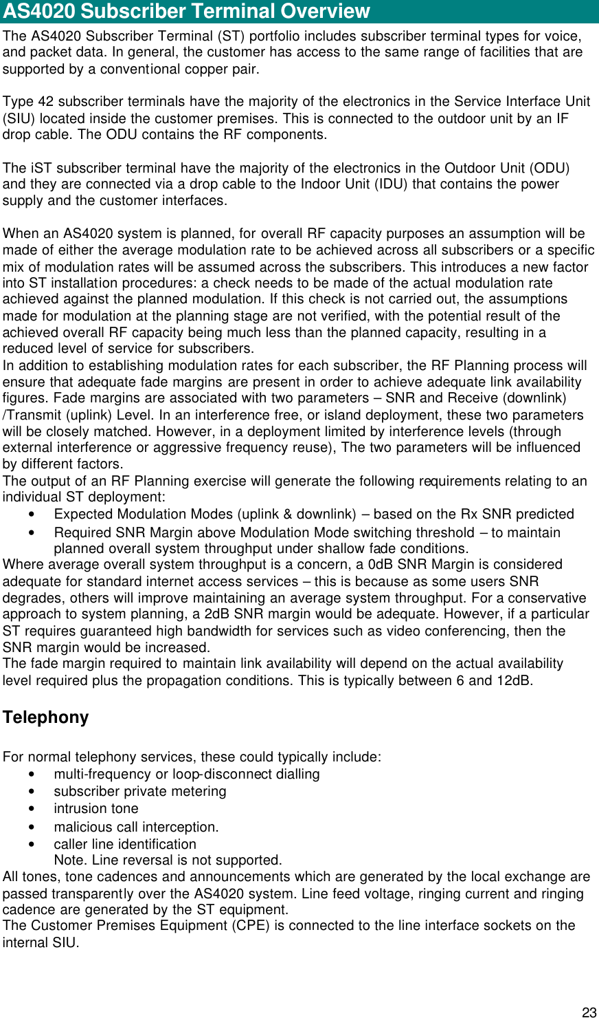
![605-0000-595 Subscriber Terminal Installation and Commissioning 34 • The ST Indoor Unit (IDU) is band/frequency independent. This allows changing IDU ST operation frequency at any time by simple reprogramming using STMON or sometimes only by changing parameters of target shelf with AS8100 [see Frequency Agility in AS8100 Sitespan help file]. • The 10baseT port is not enabled on this product](https://usermanual.wiki/Airspan-Communications/STODU-PCS/User-Guide-446538-Page-16.png)