Airspan Communications 365AS Airsynergy WiMAX Basestation User Manual Installation guide
Airspan Communications Limited Airsynergy WiMAX Basestation Installation guide
Contents
- 1. Installation guide
- 2. User Manual statements for new band
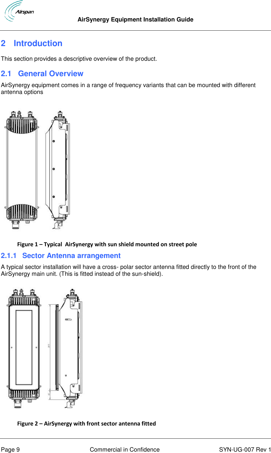
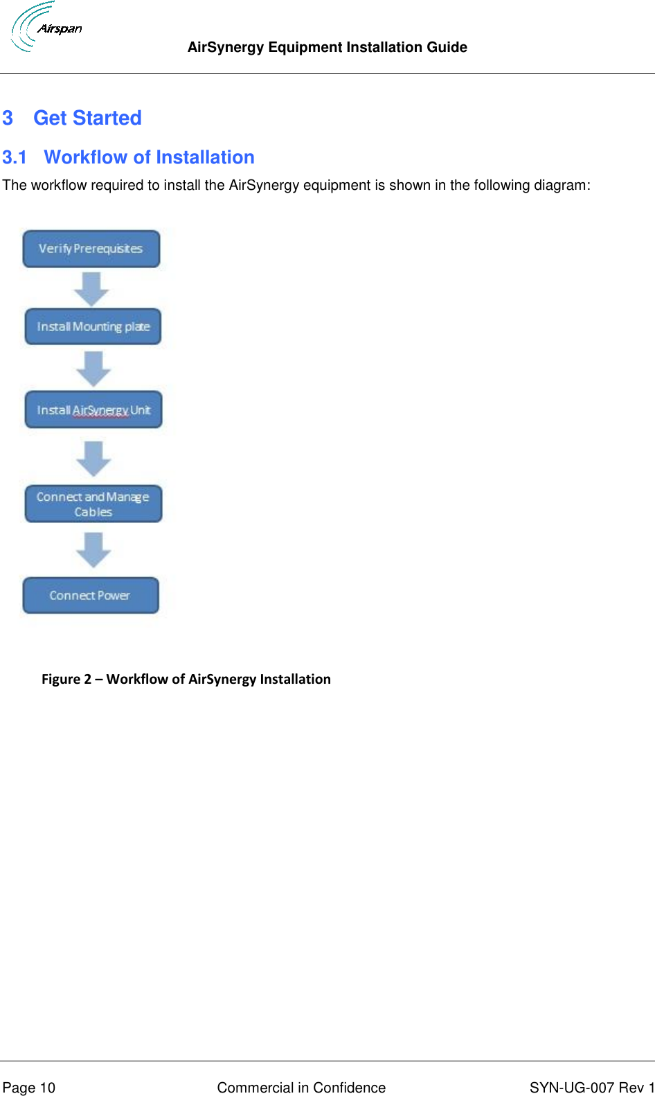
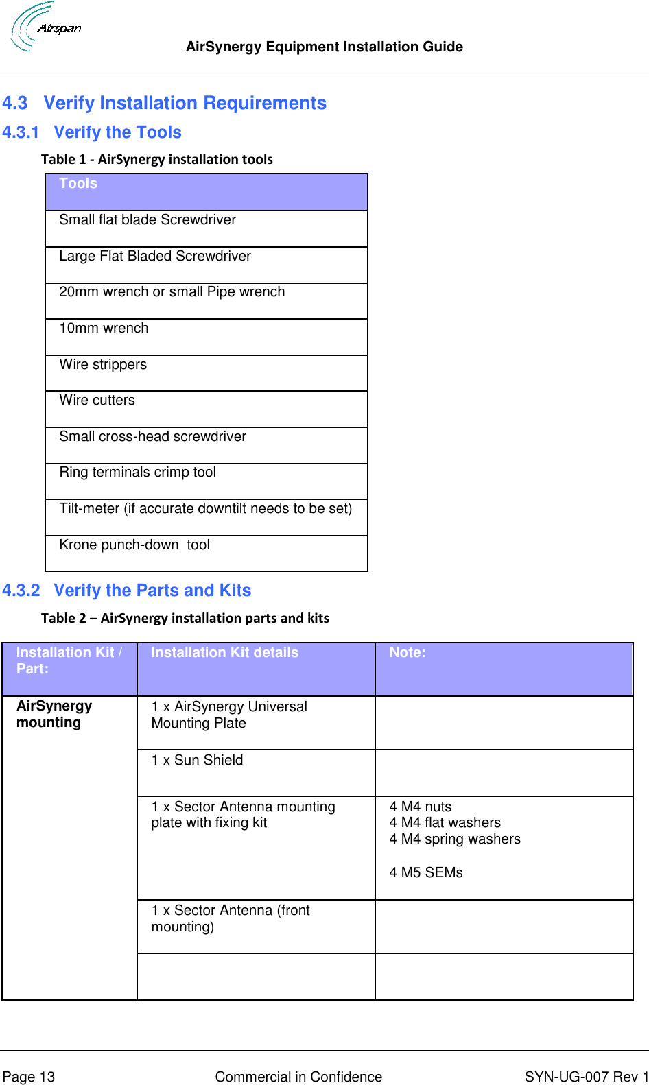
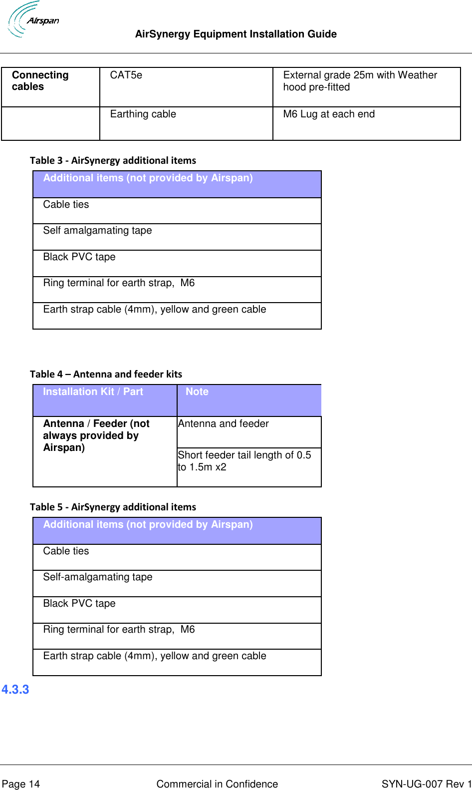
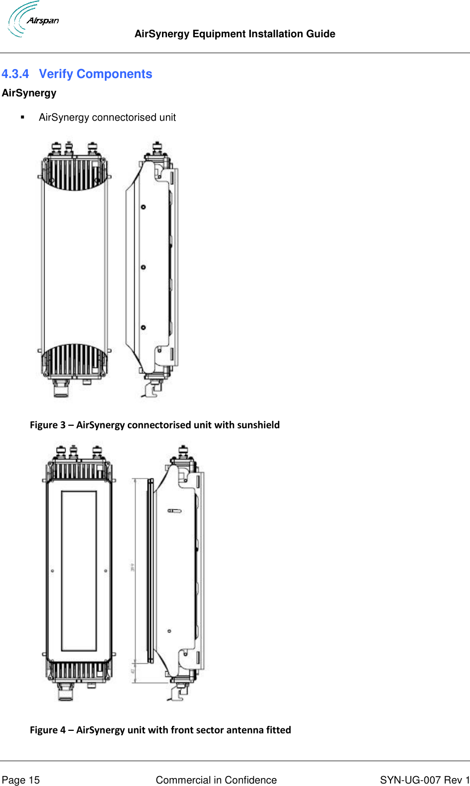
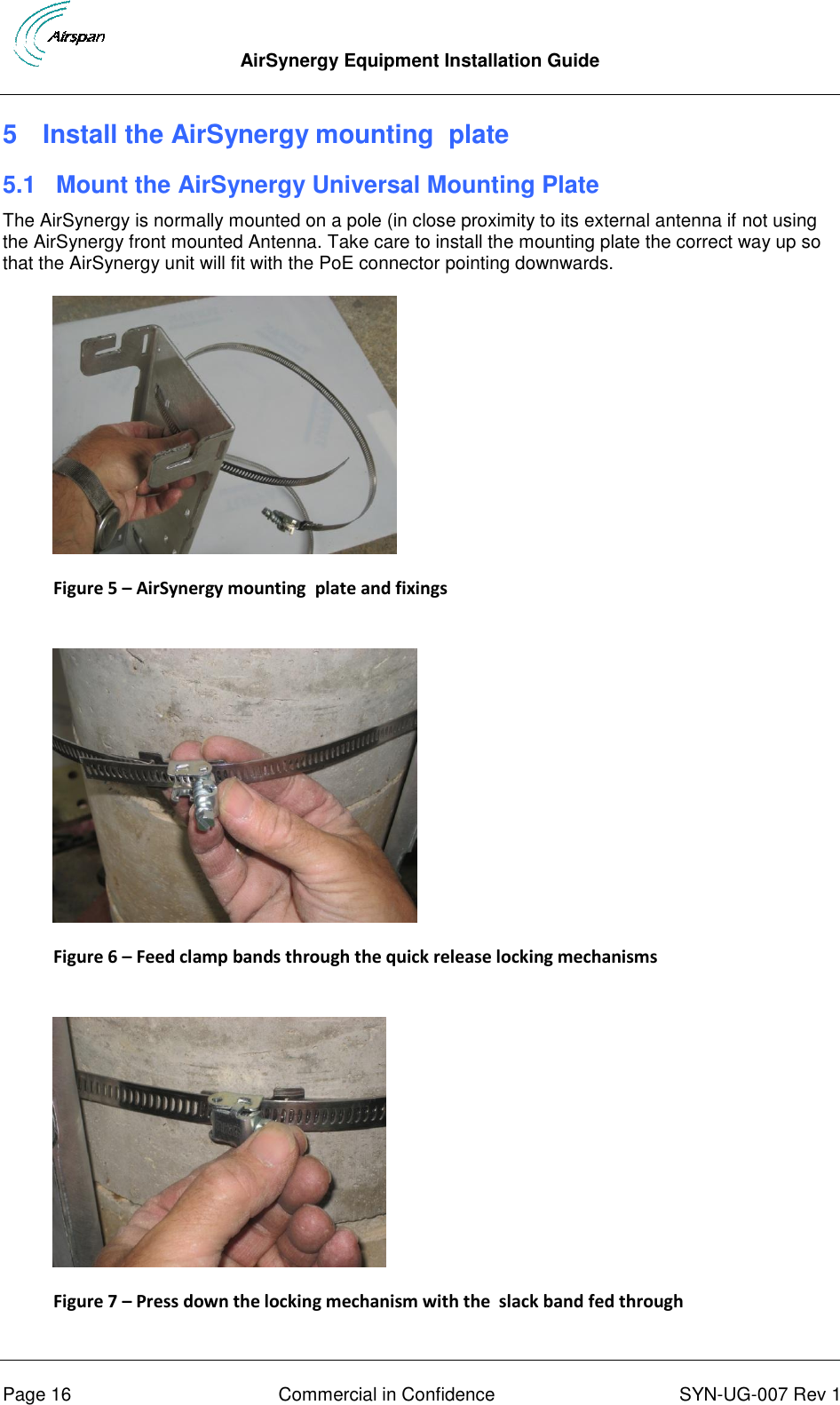
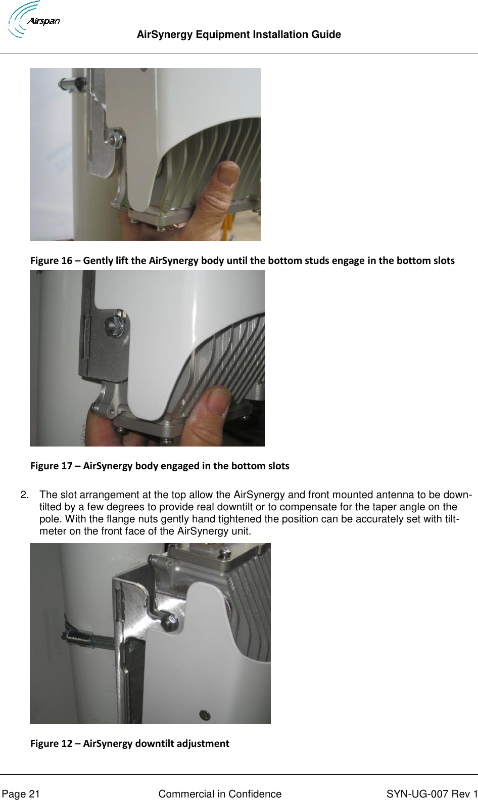
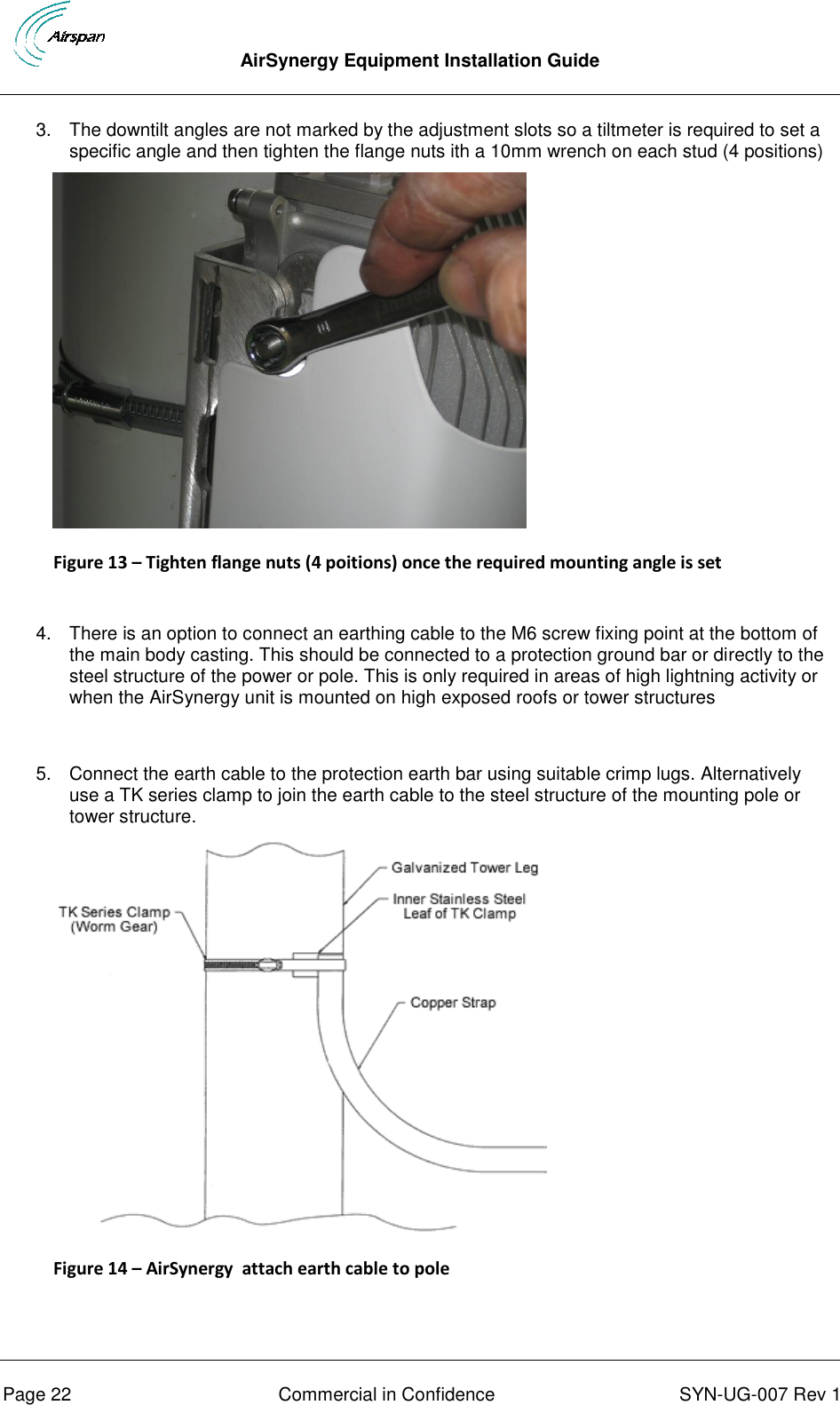
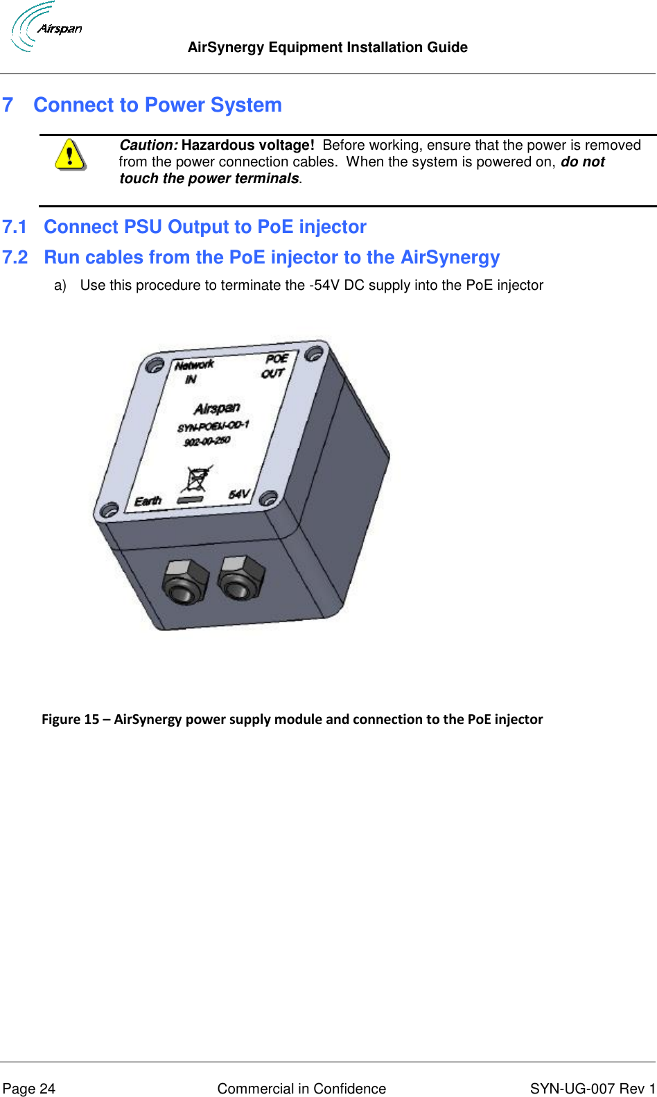
Installation guide