Advanced Radiotech FLEXSERIES Remote Control System User Manual ARC FLEX FCC
Advanced Radiotech Corporation Remote Control System ARC FLEX FCC
UserManual.wiki
>
Advanced Radiotech
>
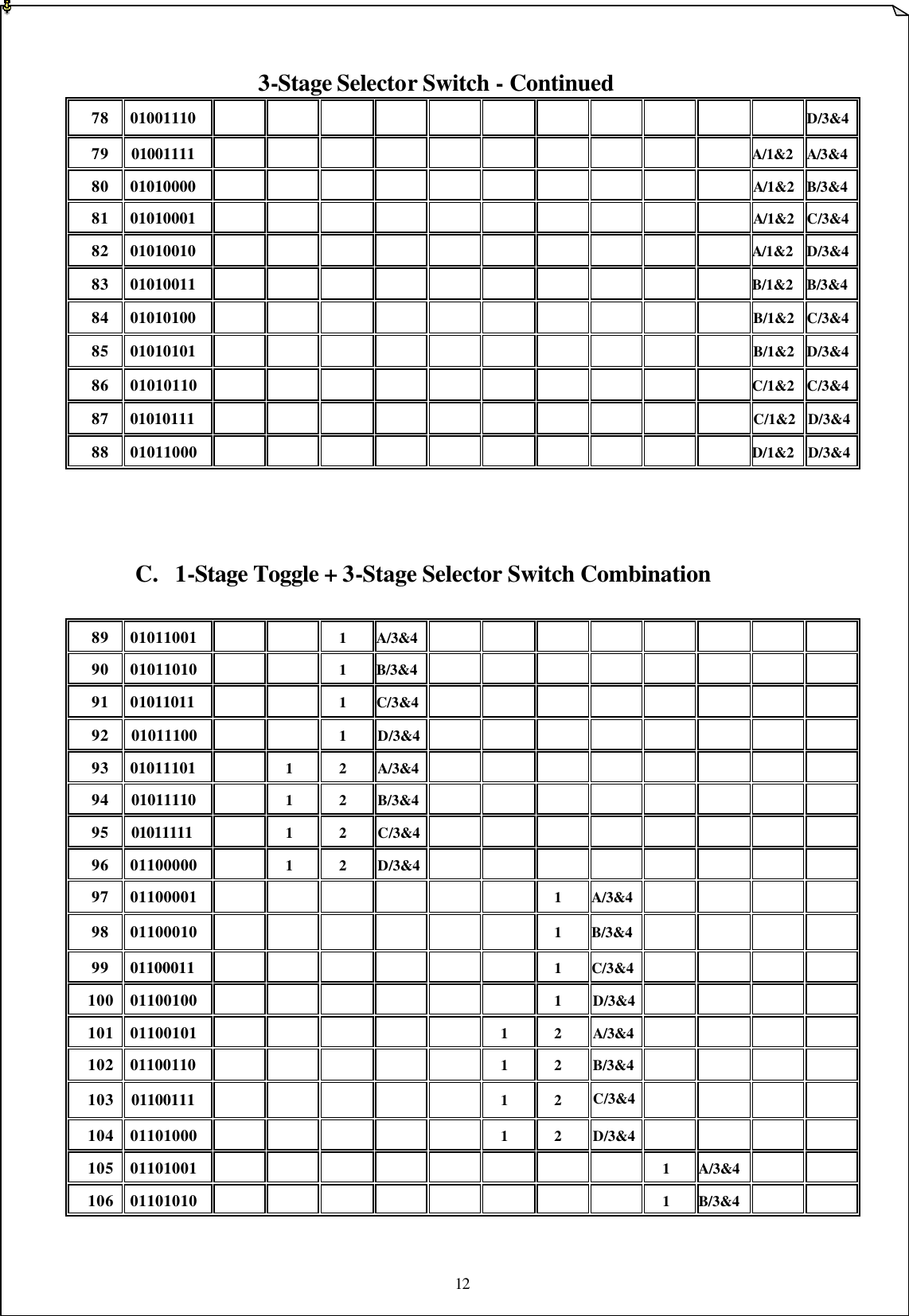
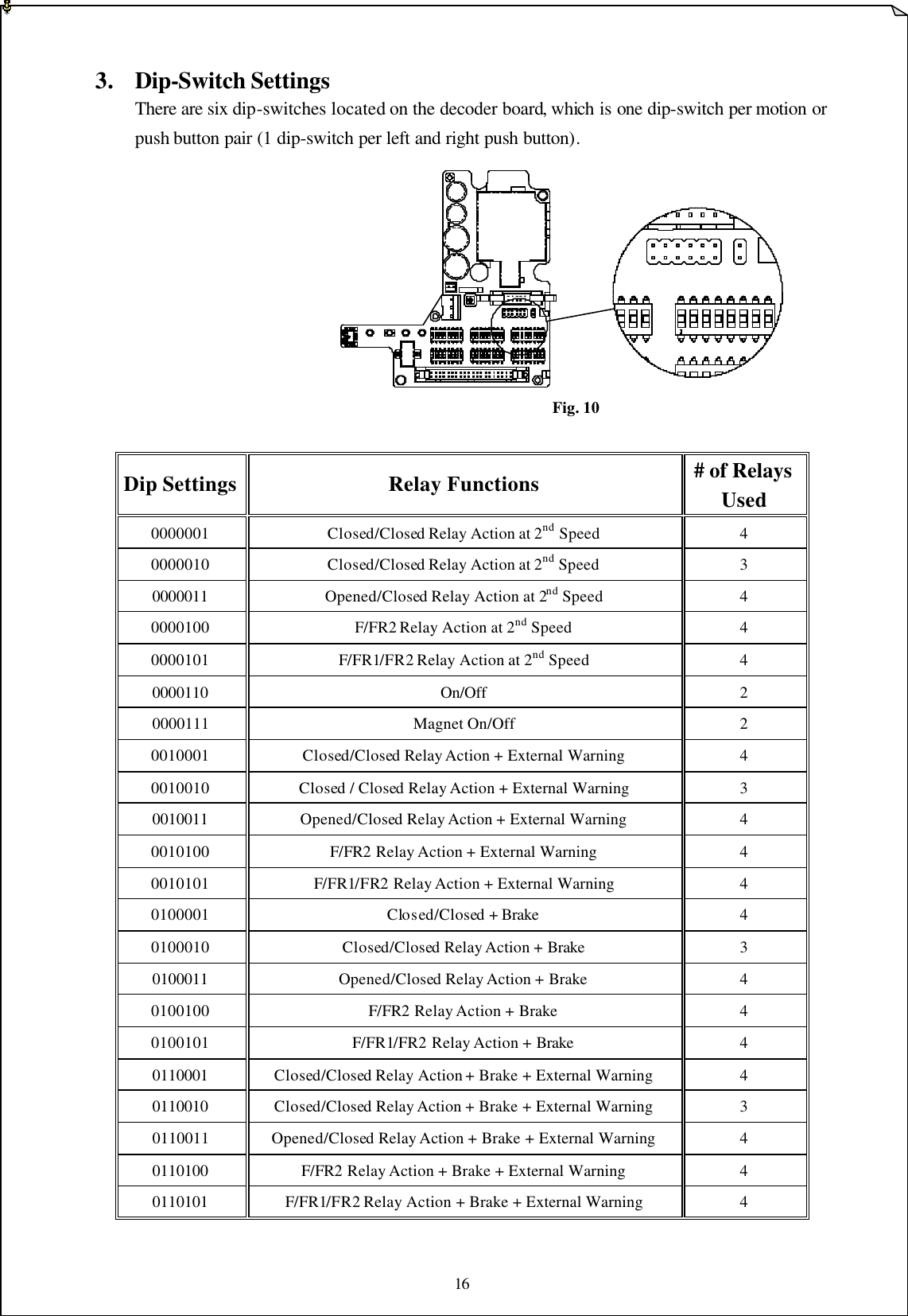
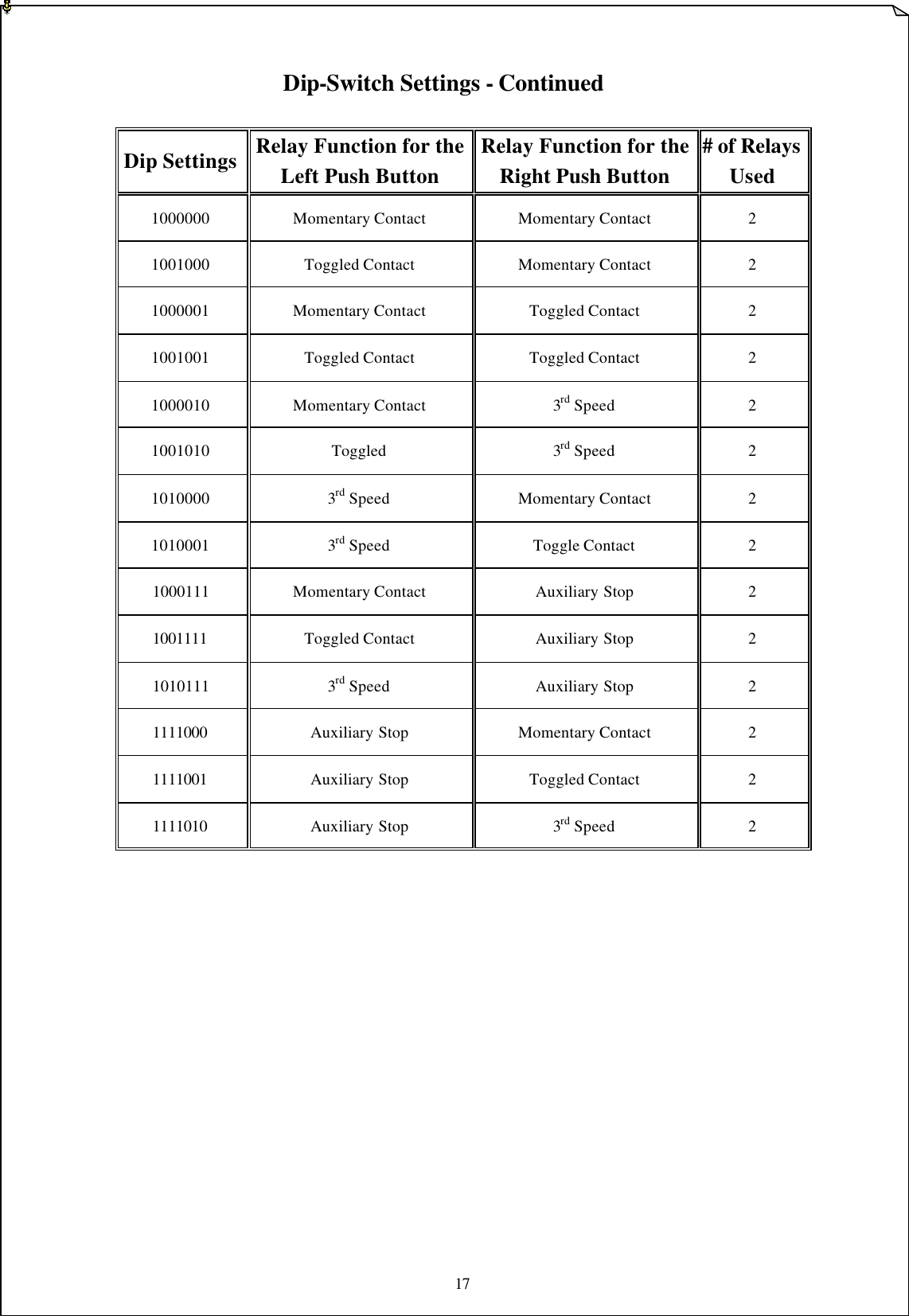
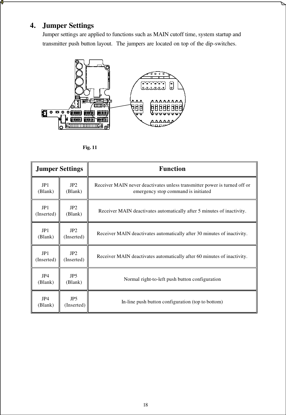
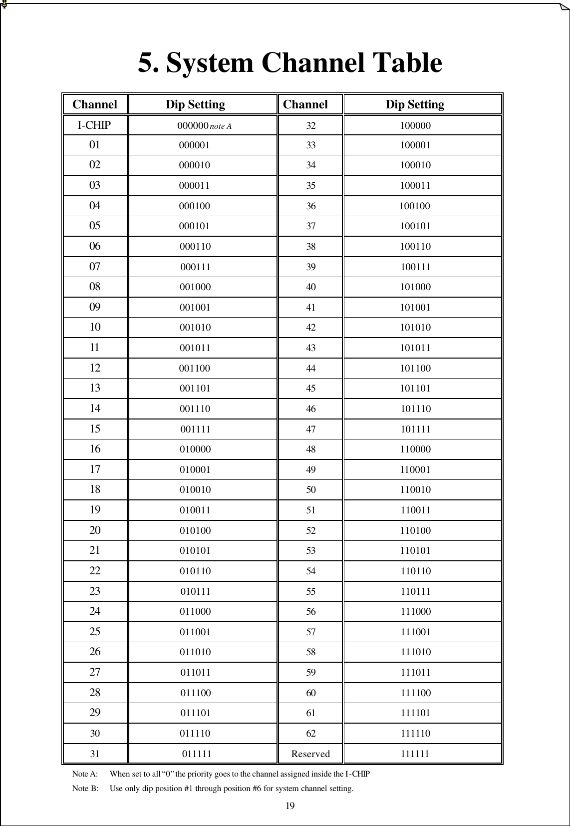
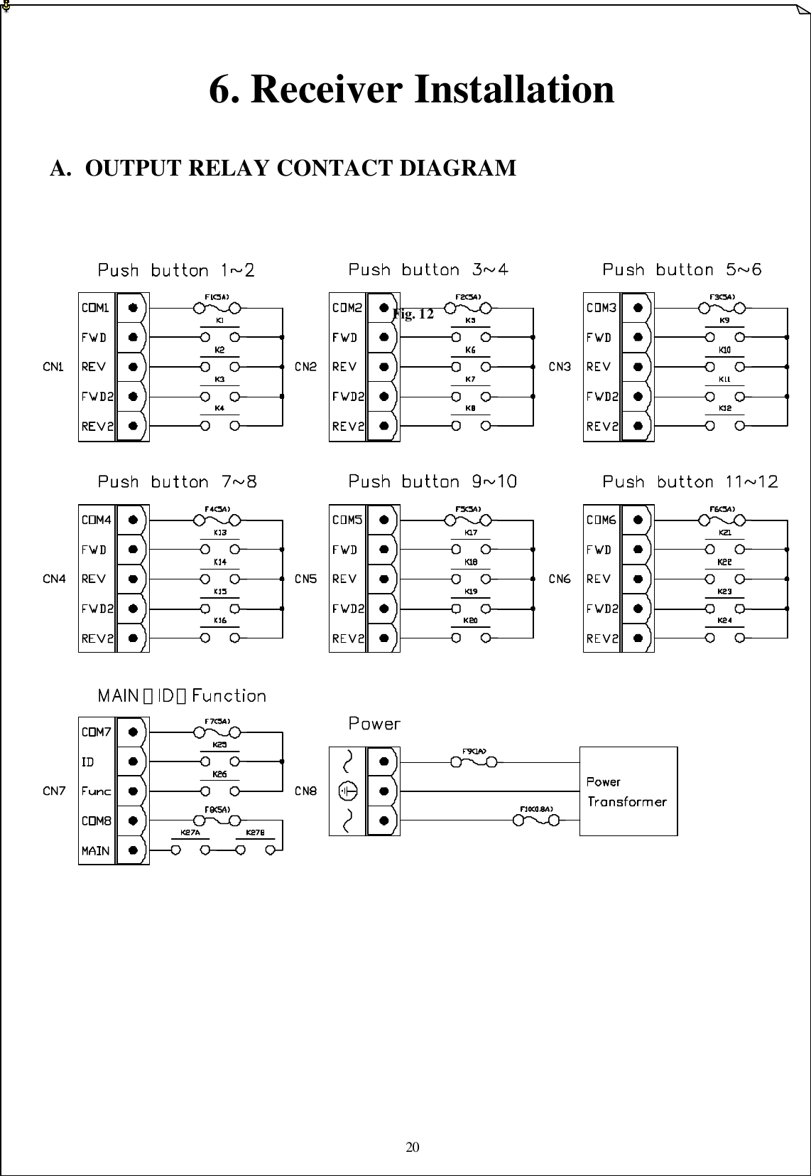
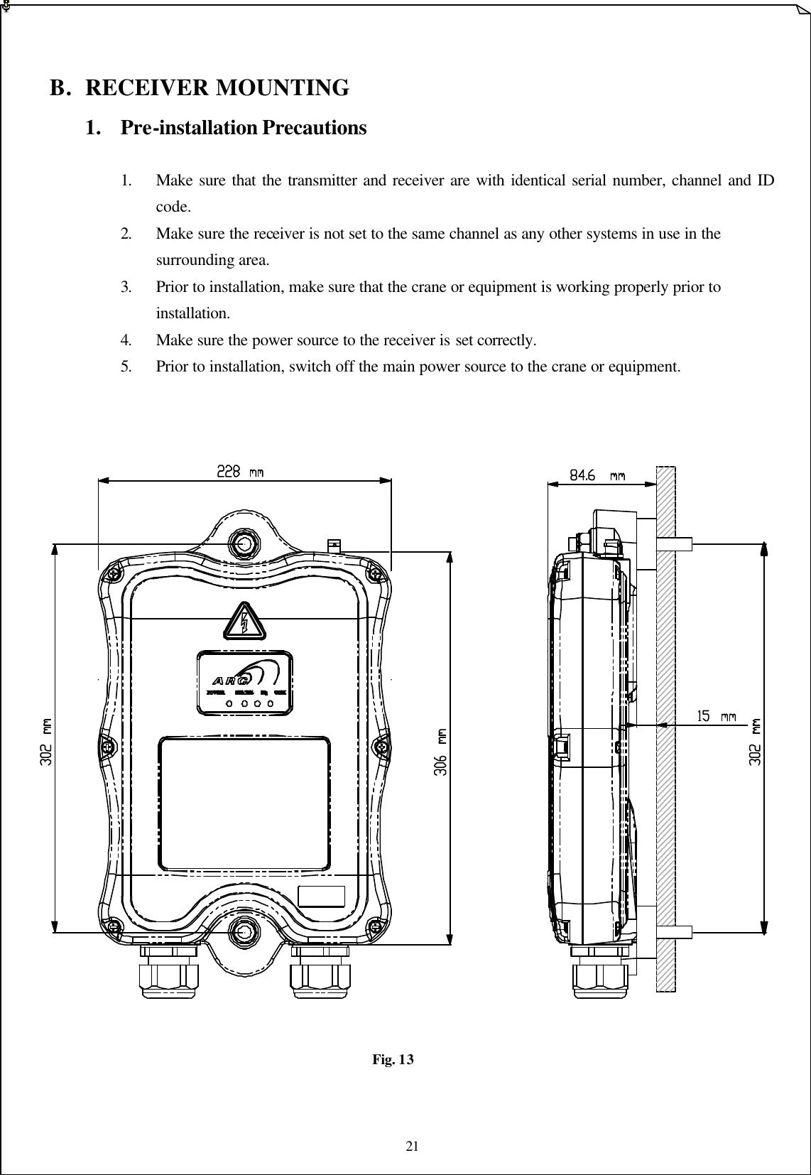
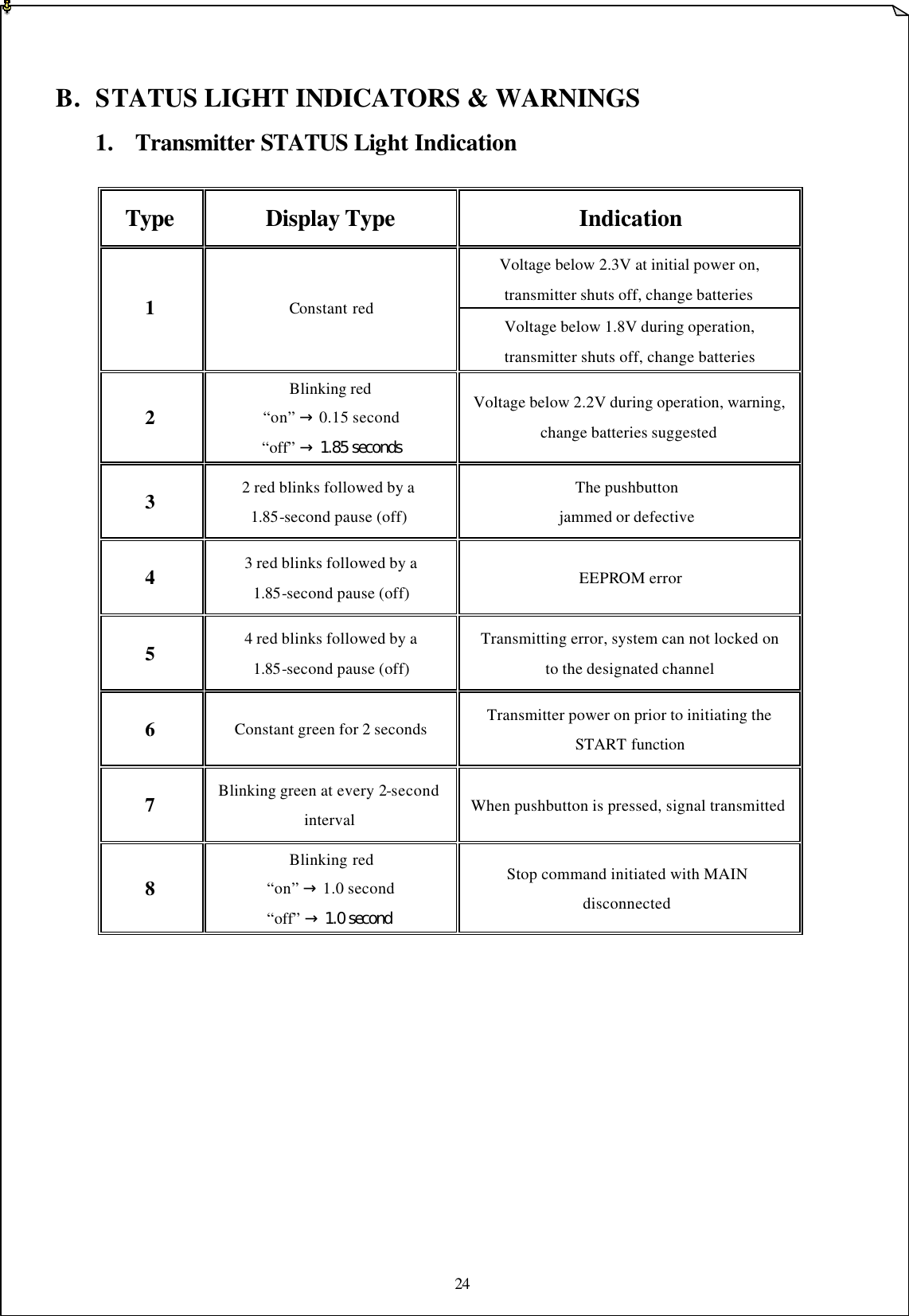
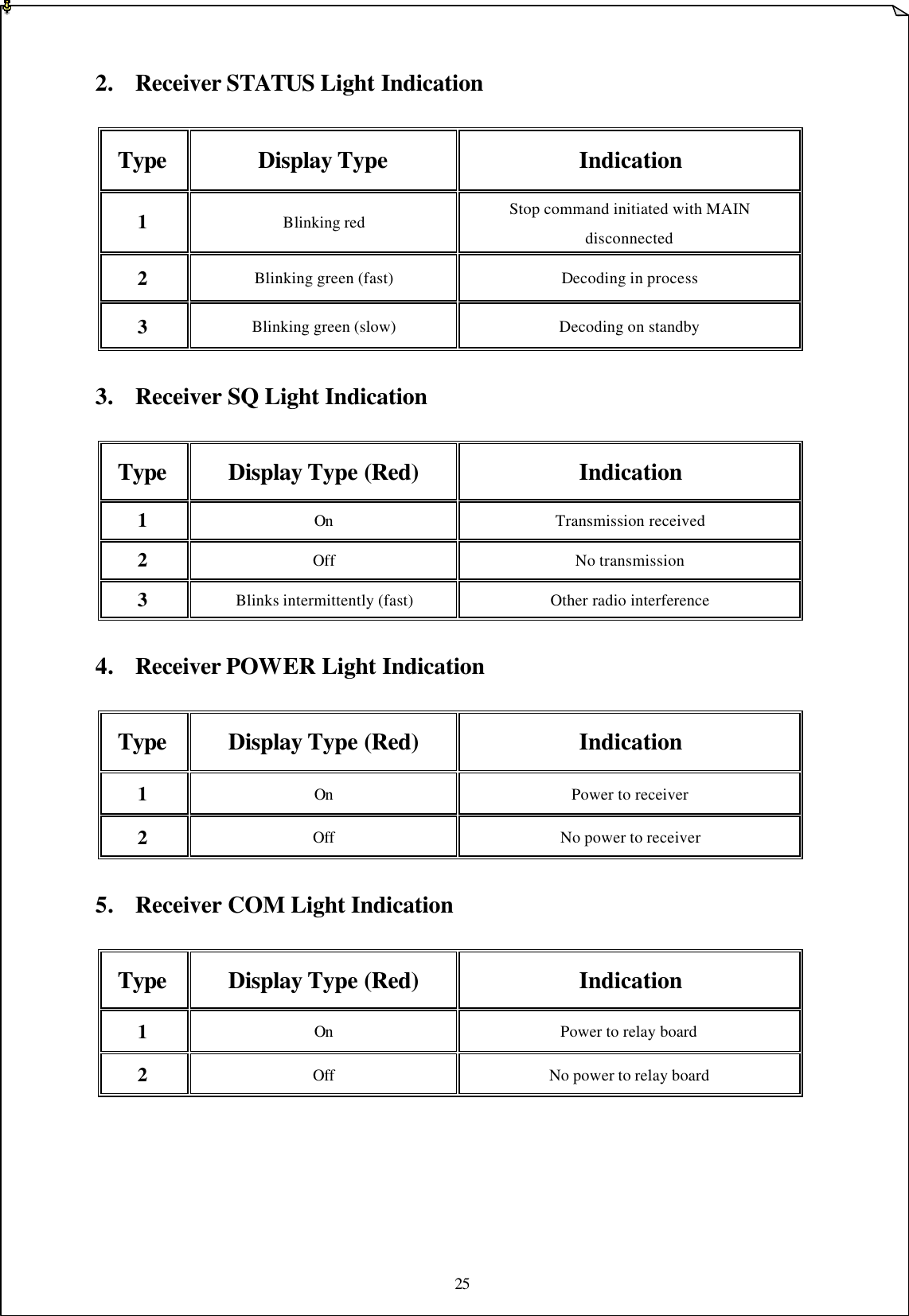
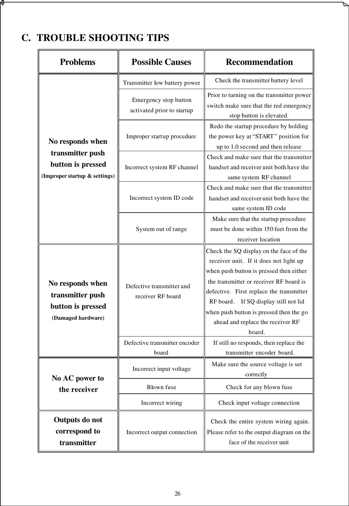
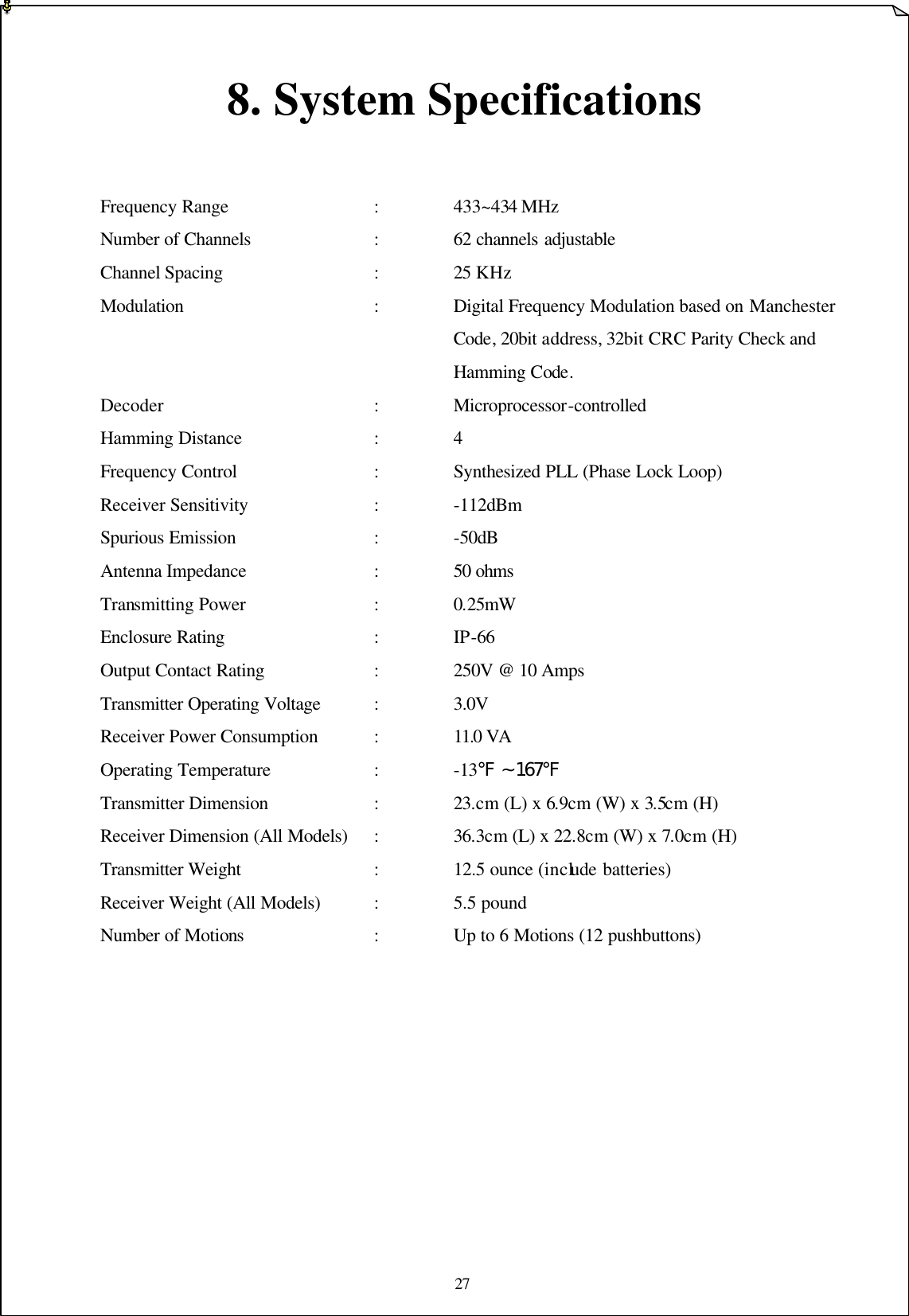
FLEXSERIES User Manual
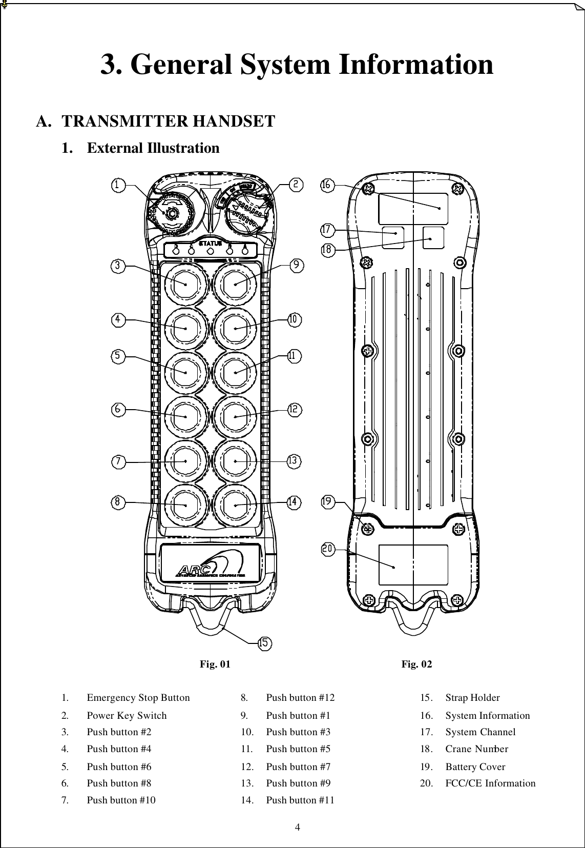
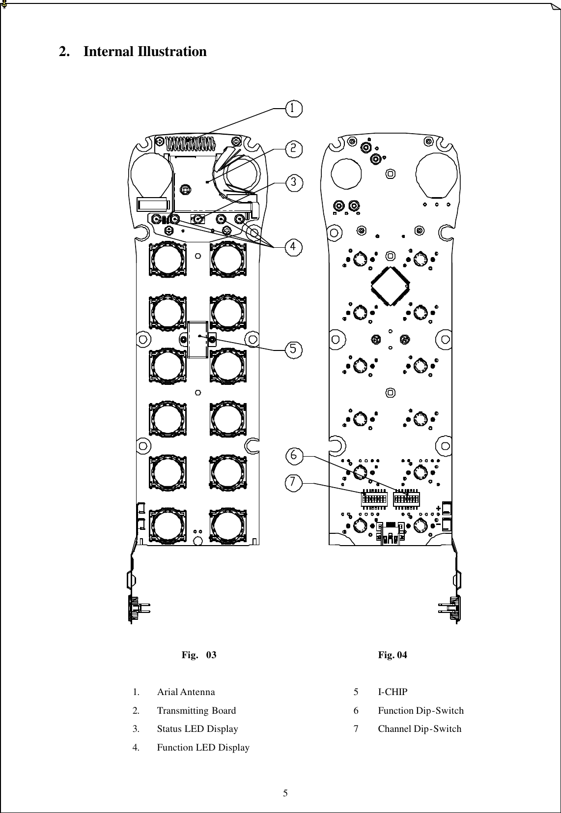
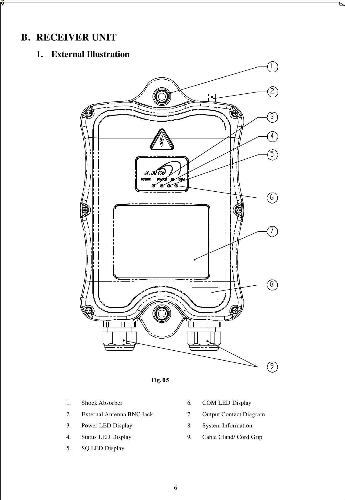
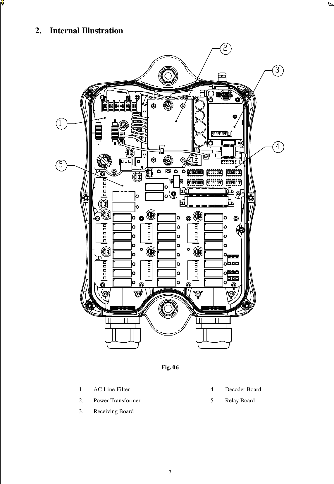
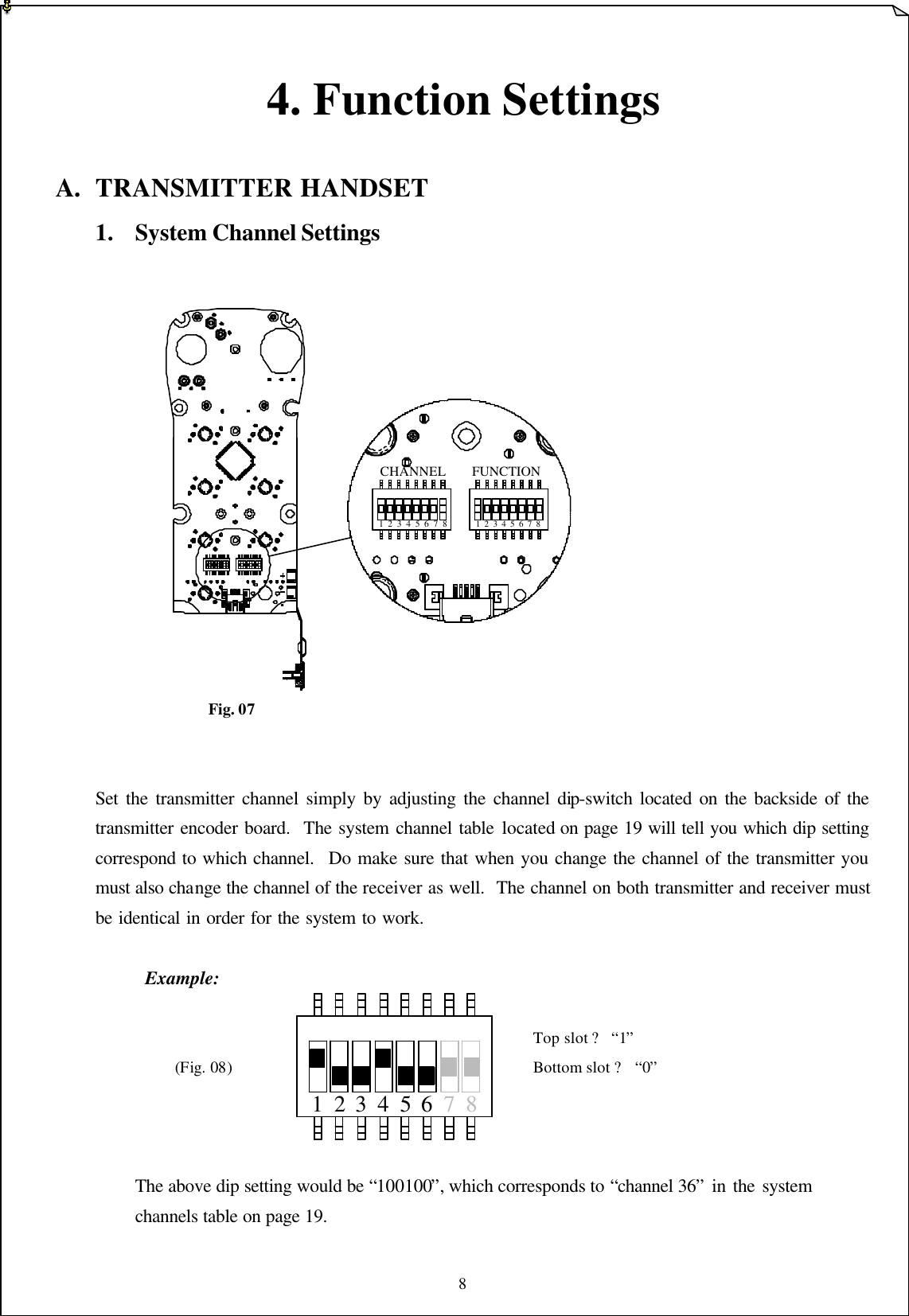
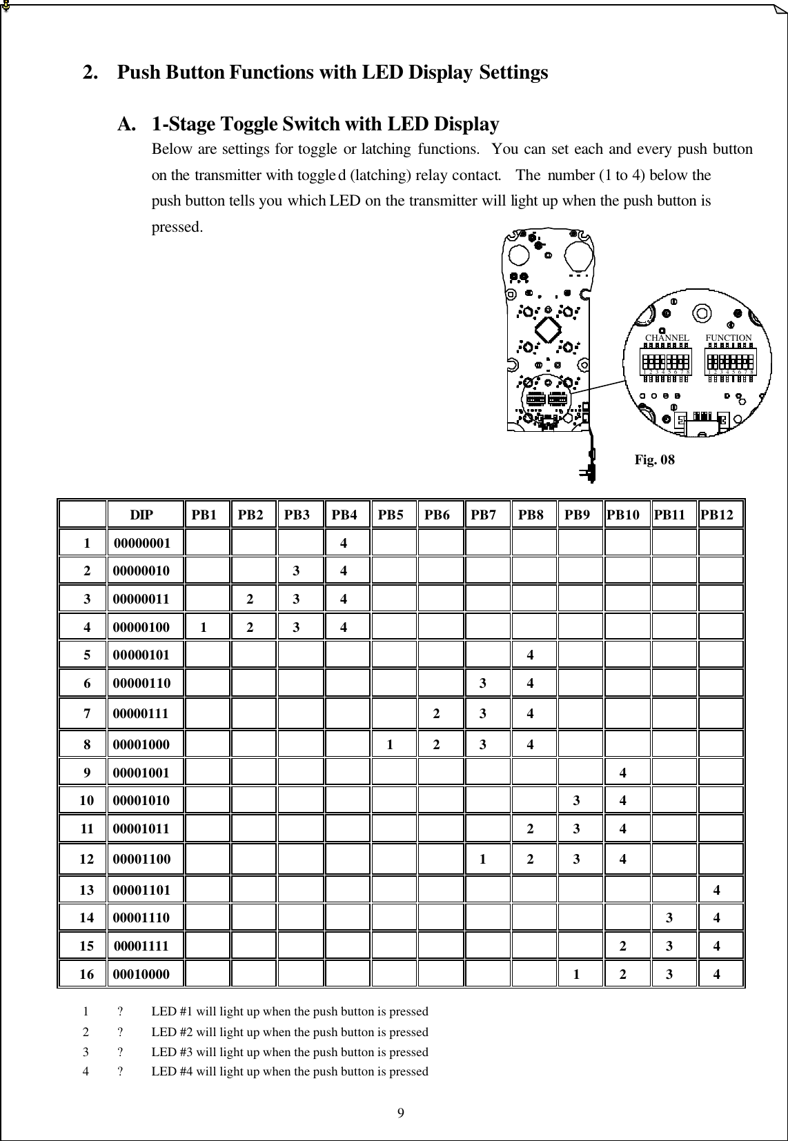
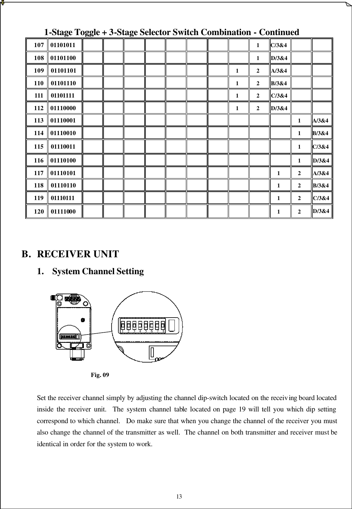
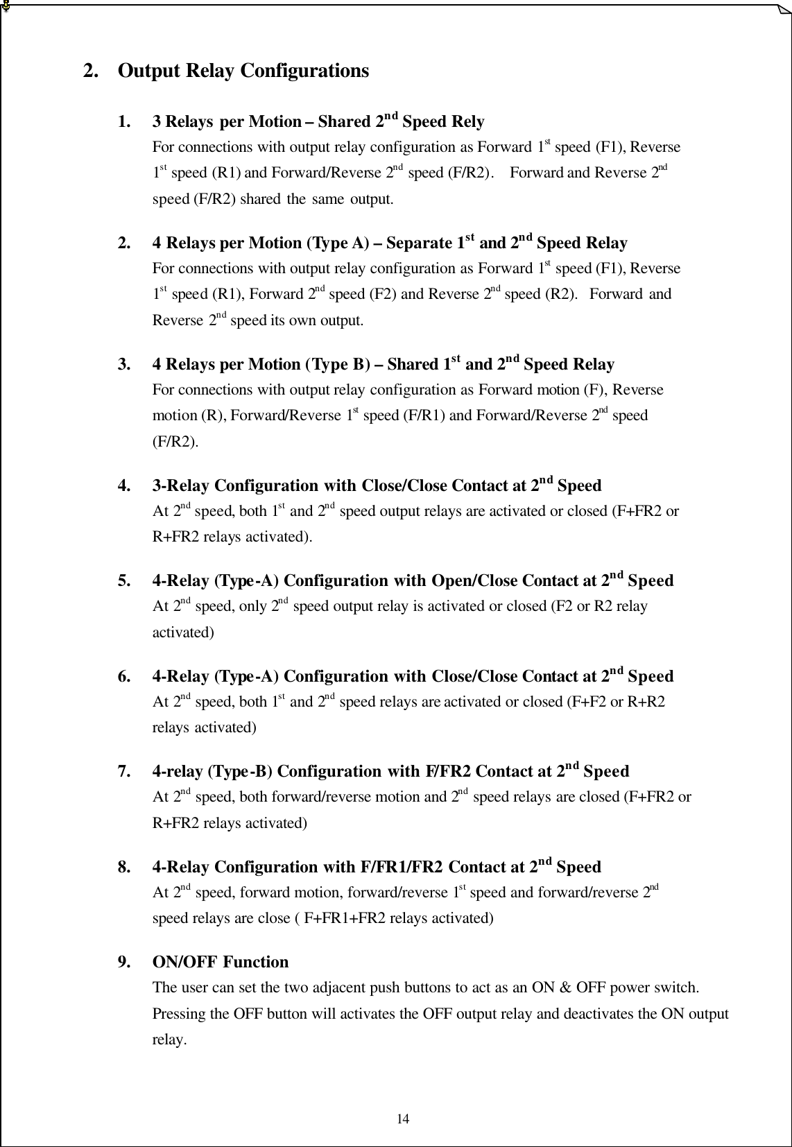
Transmitters users manual
Navigation menu
Upload a User Manual
Namespaces
Wiki Guide
HTML
PDF
Info
Views
User Manual
Discussion / Help
Navigation