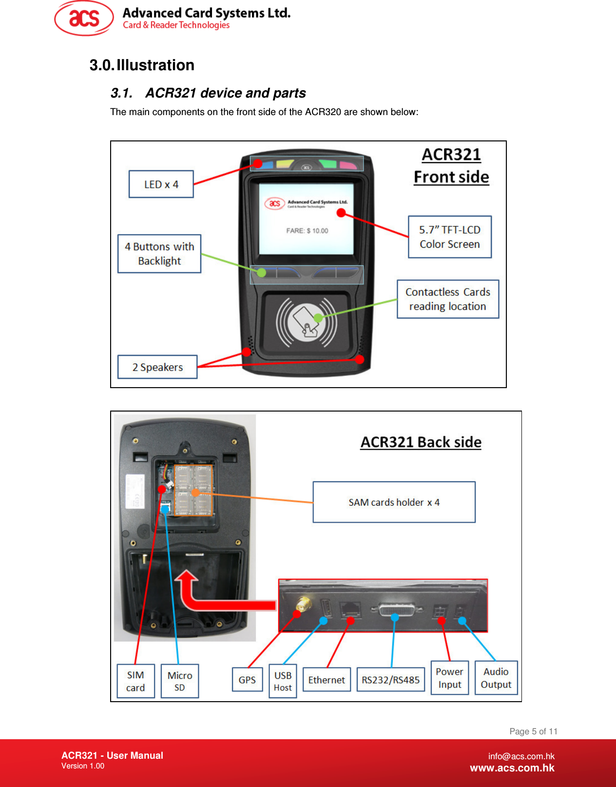
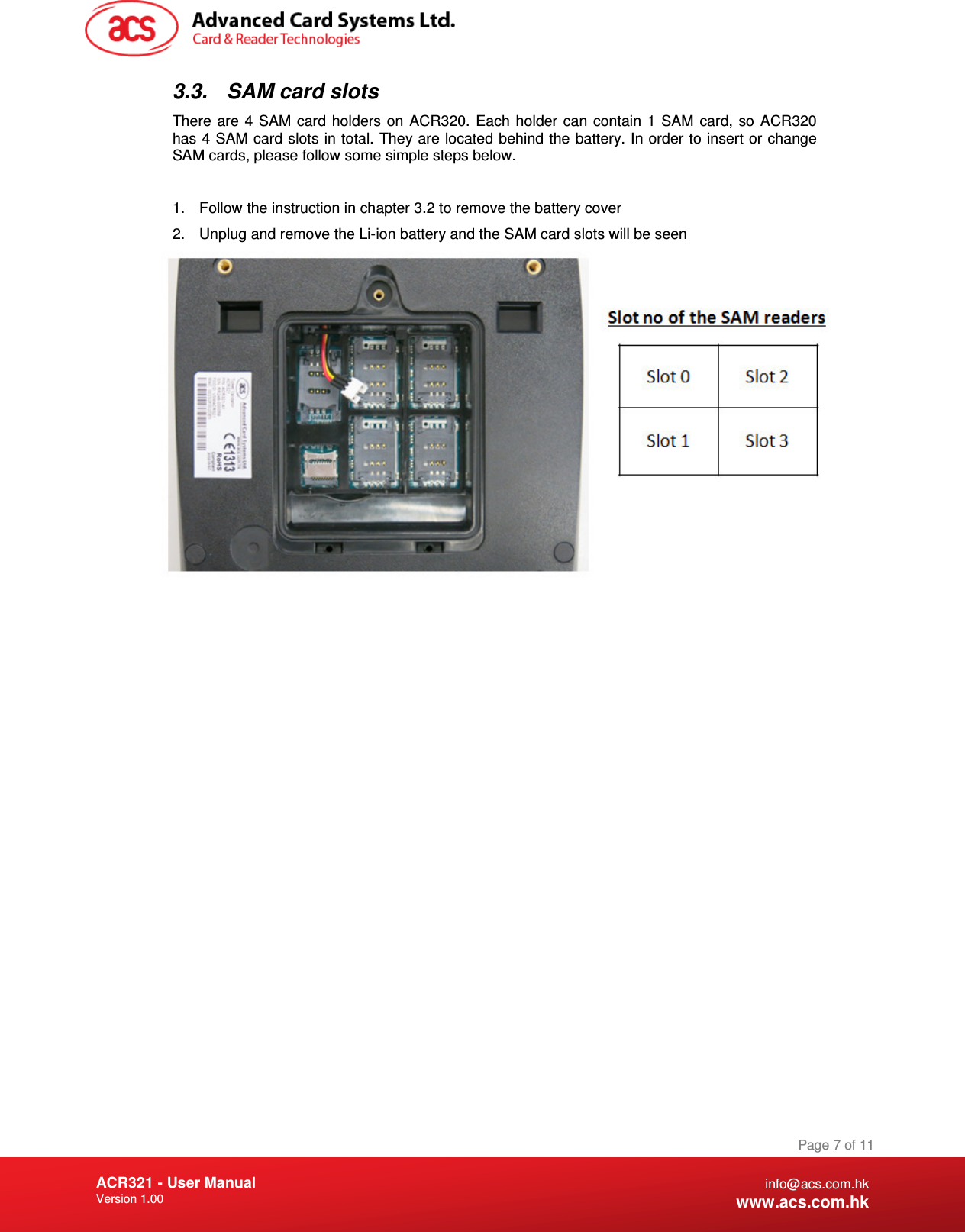
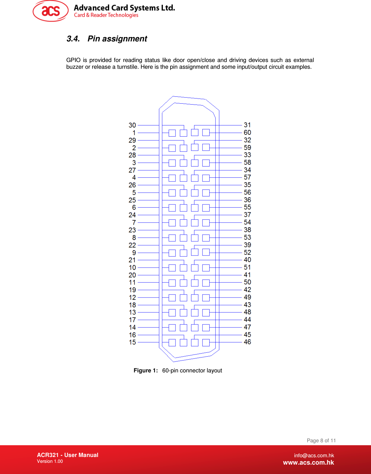
Advanced Card Systems ACR321 Ticket Validator User Manual 03 USR ACR321 1 00

Advanced Card Systems Limited Ticket Validator 03 USR ACR321 1 00

Users Manual

   Subject to change without prior notice  info@acs.com.hk www.acs.com.hk  Document Name: 03-USR-ACR321 
Document Title Here Document Title Here  Document Title Here ACR321 - User Manual Version 1.00   Page 2 of 11 info@acs.com.hk www.acs.com.hk Table of Contents 1.0. Introduction ................................................................................................................. 3 2.0. Specifications .............................................................................................................. 4 3.0. Illustration .................................................................................................................... 5 3.1. ACR321 device and parts ...................................................................................................... 5 3.2. Battery .................................................................................................................................... 6 3.3. SAM card slots ....................................................................................................................... 7 3.4. Pin assignment ...................................................................................................................... 8
Document Title Here Document Title Here  Document Title Here ACR321 - User Manual Version 1.00   Page 3 of 11 info@acs.com.hk www.acs.com.hk 1.0. Introduction  ACR321  –  Ticket  Validator  is  designed  specifically  for  the  use  in Automatic  Fare  Collection  (AFC)  systems  for  public  transport,  e.g. for buses, ferries, trams, railway and other transportation means. ACR321 supports all smart cards/tags compliant to ISO14443 Type A  & B,  Mifare,  and  Near  Field  Communication  (NFC)  standard.  By virtue of the embedded powerful 32bit ARM 11 processor,  ACR321 enables a high speed transaction processing and transaction records collection.  ACR321  supports  varies  advance  connection  modes  for data  transfer,  including  Wi-Fi,  WCDMA,  GSM/GPRS    and  USB thumb drive for data collection.  It also equips with GPS enabling you to  locate  the  vehicle,  fleet  management  and  set  fare  flexibly  with reference to distance.  There are four SAM card slots for holding Purchase SAM cards to ensure  the  security  and  integrity  of  the  transactions.  This  allows users to use their own unique secret encryption algorithm. With its compact, light and trendy design, ACR321 allows users to operate it by mounting on the pole or as a handheld ticket validator powered by rechargeable lithium-ion battery. ACR321 is furthermore integrated with a 640 x 480 high resolution VGA  5.7”  LCD,  speaker,  4  LED  indicators  with  different  colors,  4 backlit  buttons.  Adding  to  a  strict  shocking,  vibration,  water  and dust  Ingress  protection  and  reliability  testing,  ACR321  is  the  best choice of your AFC projects application. Touch Screen could be an option to further enhance the features of ACR321 that enables it suitable to be a Driver console and POS terminal.
Document Title Here Document Title Here  Document Title Here ACR321 - User Manual Version 1.00   Page 4 of 11 info@acs.com.hk www.acs.com.hk 2.0. Specifications •  32-Bit ARM11 Processor running embedded Linux  •  Flash 512 MB and RAM 256 MB •  5.7 inches TFT-LCD Color Screen •  4 LED for transaction Indicators (1 Blue, 1 Yellow, 1 Green and 1 Red) •  4 Buttons with Backlight •  Speaker with loud around 70dB in 1-meter distance •  Tamper Detection Switch to Protect Against Unauthorized Intrusion •  Supports Micro-SD memory card expansion slot •  Input : 10V to 36V unregulated DC power •  With Rechargeable Lithium-ion Battery •  Operating temperature -20 to 60 degree C •  Humidity 15% to 95% non-condensing  •  Communications o  Quad-band GSM/GPRS: 850/900/1800/1900 MHz o  WCDMA (3G) o  Wifi: IEEE 802.11 b/g o  Built-in 10/100-base-T Ethernet o  USB o  Serial – RS232,RS485 o  GPIO  •  Supported Card Types o   Contactless cards   ISO 14443 Compliant Type A & B standard   Mifare classics, Ultralight, Ultralight C, Mifare Plus, Mifare Desfire o  4 SAM cards and 1 SIM card   Support T=0,1 and ISO 7816 Parts 1-3  •  Certification / Compliance o  CE o  FCC o  RoHS o  EMV contactless o  PBOC 3.0 contactless
Document Title Here Document Title Here  Document Title Here ACR321 - User Manual Version 1.00   Page 5 of 11 info@acs.com.hk www.acs.com.hk 3.0. Illustration 3.1.  ACR321 device and parts The main components on the front side of the ACR320 are shown below:
Document Title Here Document Title Here  Document Title Here ACR321 - User Manual Version 1.00   Page 6 of 11 info@acs.com.hk www.acs.com.hk 3.2.  Battery  A  rechargeable  Li-ion  battery  supplies  energy  to  the  device  once  the  external  power  source cannot  supply  power  to  the  device.  So,  transactions  can  still  be  processed  even  the  power supply of the bus is out of order. The battery locates at back of the device. In order to change the battery, turn the screw in the circle in the figure below to left to remove the battery cover. Follow the direction of the red arrow to take away the cover.    Then, unplug the battery and a new battery can be replaced in the carrier.   The battery is recharged once the external power source resumes supplying power to the device.
Document Title Here Document Title Here  Document Title Here ACR321 - User Manual Version 1.00   Page 7 of 11 info@acs.com.hk www.acs.com.hk 3.3.  SAM card slots There are  4  SAM  card holders on  ACR320. Each  holder  can  contain  1  SAM  card,  so  ACR320 has 4 SAM card slots in total. They are located behind the battery. In order to insert or change SAM cards, please follow some simple steps below.  1.  Follow the instruction in chapter 3.2 to remove the battery cover 2.  Unplug and remove the Li-ion battery and the SAM card slots will be seen
Document Title Here Document Title Here  Document Title Here ACR321 - User Manual Version 1.00   Page 8 of 11 info@acs.com.hk www.acs.com.hk 3.4.  Pin assignment   GPIO  is  provided  for  reading  status  like  door  open/close  and  driving  devices  such  as  external buzzer or release a turnstile. Here is the pin assignment and some input/output circuit examples.    Figure 1:  60-pin connector layout
Document Title Here Document Title Here  Document Title Here ACR321 - User Manual Version 1.00   Page 9 of 11 info@acs.com.hk www.acs.com.hk  Signal  Signal Name  Signal Description  Signal Level 1  RS232/485  Port 1: 3.3V or open->RS232, 0V-> RS485  3.3V logic 2  TXD1  RS232 Port 1, Data Transmit  RS-232 signal standard 3  RXD1  RS232 Port 1, Data Receive  RS-232 signal standard 4  RS485-A  RS485 Non-inverting, Port 1  RS485 signal standard 5  RS485-B  RS485 Inverting, Port 1  RS485 signal standard 6  GND  Digital Ground  Digital Ground for Serial port interface 7  TXD2  RS232 Port 2, Data Transmit  RS-232 signal standard 8  RXD2  RS232 Port 2, Data Receive  RS-232 signal standard 9  GND  Digital Ground  Digital Ground for Serial port interface 10  N.C.  No connection    11  N.C.  No connection    12  N.C.  No connection    13  N.C.  No connection    14  N.C.  No connection    15  Reserved  (Don't connect)    16  N.C.  No connection    17  N.C.  No connection    18  N.C.  No connection    19  Reserved  (Don't connect)    20  Reserved  (Don't connect)    21  Reserved  (Don't connect)    22  Reserved  (Don't connect)    23  OUTPUT-8  OUTPUT port 8  3V/5V Logic Level 24  OUTPUT-7  OUTPUT port 7  3V/5V Logic Level 25  OUTPUT-6  OUTPUT port 6  3V/5V Logic Level 26  OUTPUT-5  OUTPUT port 5  3V/5V Logic Level 27  N.C.  No connection    28  N.C.  No connection    29  N.C.  No connection    30  N.C.  No connection
Document Title Here Document Title Here  Document Title Here ACR321 - User Manual Version 1.00   Page 10 of 11 info@acs.com.hk www.acs.com.hk 31  Reserved  (Don't connect)    32  Reserved  (Don't connect)    33  Reserved  (Don't connect)    34  Reserved  (Don't connect)    35  V_EXTIN2  Isolated power-in for Input port 5-8  3V/5V 36  V_EXTIN2  Isolated power-in for Input port 5-8  3V/5V  37  G_EXTIN2  Isolated GND for Input port 5-8  Ground signal for input port 38  G_EXTIN2  Isolated GND for Input port 5-8  Ground signal for input port 39  V_EXTOUT2  Isolated power-in for Output port 5-8  3V/5V 40  V_EXTOUT2  Isolated power-in for Output port 5-8  3V/5V 41  N.C.  No connection    42  N.C.  No connection    43  CAR-GND  CAR  Battery Ground  Car battery Ground  44  CAR-GND  CAR  Battery Ground  Car battery Ground  45  CAR-GND  CAR  Battery Ground  Car battery Ground  46  CAR-DC  Car Battery +  Car Battery Positive (12V~24V) 47  CAR-DC  Car Battery +  Car Battery Positive (12V~24V) 48  CAR-DC  Car Battery +  Car Battery Positive (12V~24V) 49  N.C.  No connection    50  G_EXTOUT2  Isolated GND for Output port 5-8  Ground signal for output port 51  G_EXTOUT2  Isolated GND for Output port 5-8  Ground signal for output port 52  TACHOMETER_IN  INPUT port 8, Tachometer  3V/5V Logic Level 53  EXT_IO_IN7A  INPUT port 7  3V/5V Logic Level 54  EXT_IO_IN6A  INPUT port 6  3V/5V Logic Level 55  EXT_IO_IN5A  INPUT port 5  3V/5V Logic Level 56  N.C.  No connection    57  N.C.  No connection    58  N.C.  No connection    59  N.C.  No connection    60  N.C.  No connection     Table 1:  60-way connector signal level and description
Document Title Here Document Title Here  Document Title Here ACR321 - User Manual Version 1.00   Page 11 of 11 info@acs.com.hk www.acs.com.hk   Figure 2:  Input circuit example      Figure 3:  Output controlling example - Lamp      Figure 4:  Output controlling example - Relay
FCC Caution:  Any Changes or modifications not expressly approved by the party responsible for compliance could void the user's    authority to operate the equipment.  This device complies with part 15 of the FCC Rules. Operation is subject to the following two conditions: (1) This device may not cause harmful interference, and (2) this device must accept any interference received, including    interference that may cause undesired operation.  Note: This equipment has been tested and found to comply with the limits for a Class B digital device, pursuant to    part 15 of the FCC Rules. These limits are designed to provide reasonable protection against harmful interference in    a residential installation. This equipment generates, uses and can radiate radio frequency energy and, if not installed    and used in accordance with the instructions, may cause harmful interference to radio communications. However,    there is no guarantee that interference will not occur in a particular installation. If this equipment does cause harmful    interference to radio or television reception, which can be determined by turning the equipment off and on, the user is   encouraged to try to correct the interference by one or more of the following measures:      —Reorient or relocate the receiving antenna.      —Increase the separation between the equipment and receiver.      —Connect the equipment into an outlet on a circuit different from that to which the receiver is connected.    —Consult the dealer or an experienced radio/TV technician for help.      IMPORTANT NOTE:      FCC Radiation Exposure Statement:      This equipment complies with FCC radiation exposure limits set forth for an uncontrolled environment .This equipment should be installed and operated with minimum distance 20cm between the radiator& your body.      This transmitter must not be co-located or operating in conjunction with any other antenna or transmitter.

Navigation menu