Adaptrum ACRS20F Fixed TV Band Device User Manual revised acrs20 user manual

Adaptrum, Inc Fixed TV Band Device revised acrs20 user manual

Contents

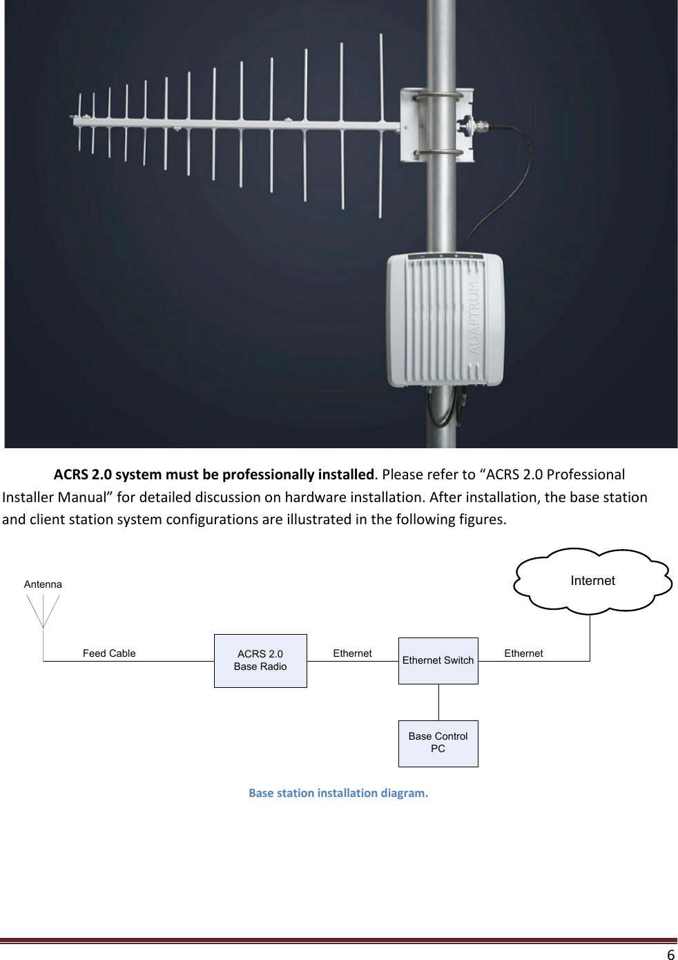
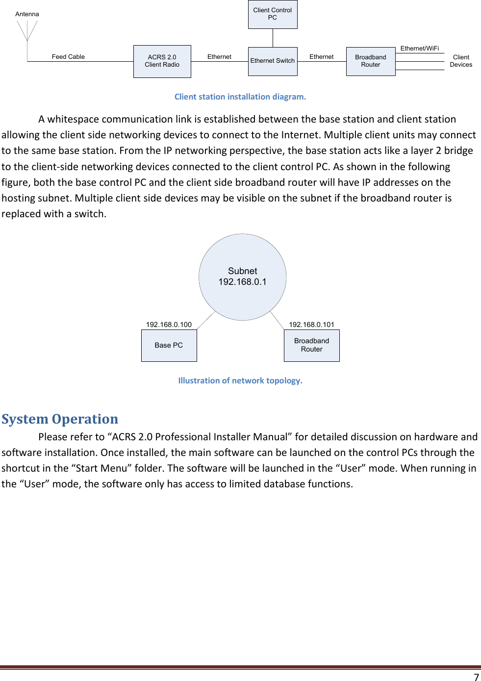
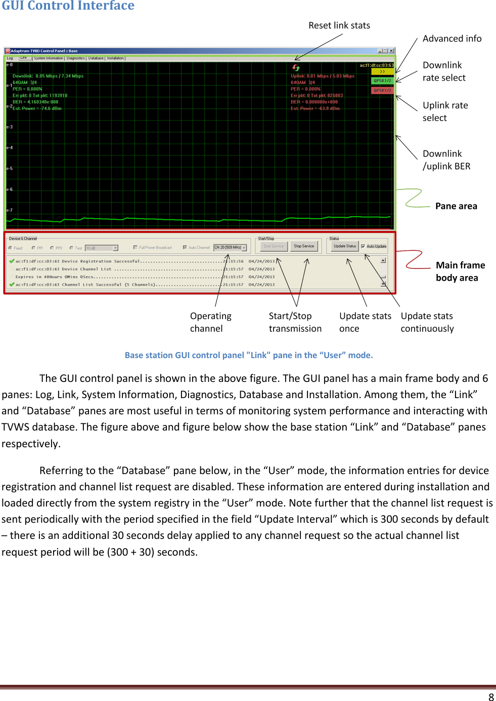
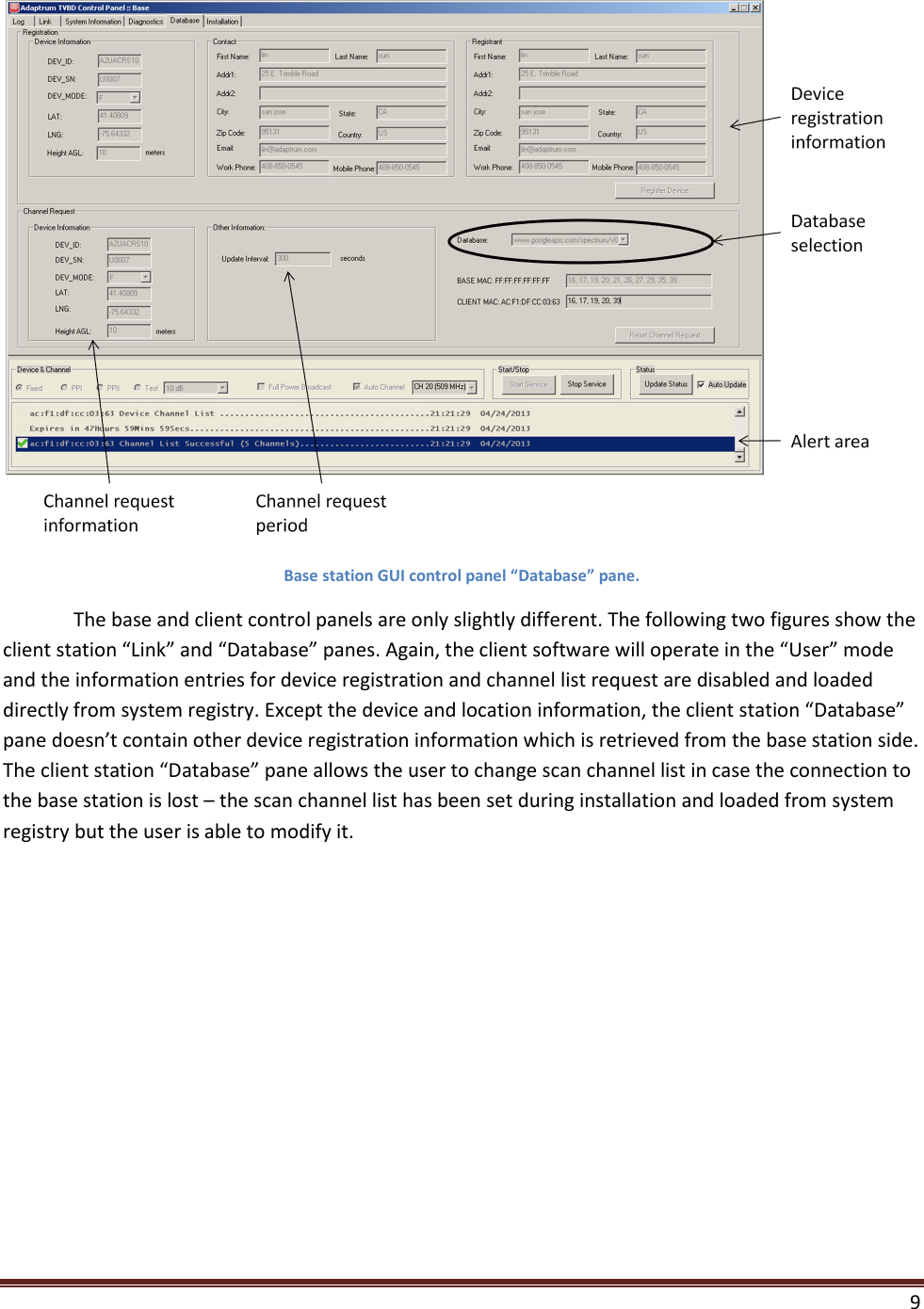
revised acrs20_user_manual

   1     ACRS 2.0 User Manual
   2  FCC Regulatory Information This device complies with part 15 of the FCC Rules. Operation is subject to the following two conditions: (1) This device may not cause harmful interference, and (2) this device must accept any interference received, including interference that may cause undesired operation. Any changes or modifications not expressly approved by the party responsible for compliance could void the user’s authority to operate the equipment. Part 15 TV Band Device Notice This equipment has been tested and found to comply with the rules for TV bands devices, pursuant to part 15 of the FCC rules. These rules are designed to provide reasonable protection against harmful interference. This equipment generates, uses and can radiate radio frequency energy and, if not installed and used in accordance with the instructions, may cause harmful interference to radio communications. If this equipment does cause harmful interference to radio or television reception, which can be determined by turning the equipment off and on, the user is encouraged to try to correct the interference by one or more of the following measures: (1) Reorient or relocate the receiving antenna. (2) Increase the separation between the equipment and receiver. (3) Connect the equipment into an outlet on a circuit different from that to which the receiver is connected. (4) Consult the manufacturer, dealer or an experienced radio/TV technician for help. Caution: Exposure to Radio Frequency Radiation. To comply with FCC RF exposure compliance requirements, for fixed configurations, a separation distance of at least 40 cm must be maintained between the antenna of this device and all persons.  This device must not be co-located or operating in conjunction with any other antenna or transmitter.
   3  Introduction ACRS 2.0 is the second generation Adaptrum cognitive radio system covering spectrum bands from 400 MHz to 1 GHz. Although capable to operate in other spectrum bands below 1 GHz, Adaptrum ACRS 2.0 is specifically designed to operate in the UHF TV Band (470 MHz – 698 MHz), as TV Band Devices compliant to the rules specified in CFR 47 Part 15 Subpart H. To be rules-compliant, ACRS 2.0 systems must operate as Fixed TV Band Devices and must be professionally installed. ACRS 2.0 system specifications are shown in the following table.  General Specifications Regulatory Compliance FCC Part 15 Subpart H Technology TDD OFDMA Network topology Point to Multi-Point Mobility Support Nomadic & Vehicular up to 40 m/s Frequency Range 400 MHz – 1000 MHz Channel Bandwidth Flexible up to 10 MHz Supporting 6, 7, 8 MHz TV channels Aggregated Layer 2 Data Rate  (Uplink + Downlink) / 6MHz 1 Mbps – 16 Mbps Uplink/Downlink Ratio Any e.g. 1:1, 1:3, 4:1 Transmit Power 100 mW conducted Channel Bandwidth Efficiency 94 percent Adjacent Channel Emission < -55 dBc Receiver Sensivity (6 MHz Channel) Level SNR Data Throughput -98 dBm 3.5 dB 2.7 Mbps (QPSK 1/2) -90 dBm 11.5 dB 7.1 Mbps (16 QAM 2/3) -81 dBm 20.5 dB 12 Mbps (64 QAM 3/4) Interface Specifications Optional external antenna connector SMA Female Data/Control    10/100 Ethernet Electrical and Mechanical Specifications Supply 48 V PoE Physical Dimensions 8.5 inches x 7.5 inches x 1.5 inches Weight 3.6 LB Table 1: Adaptrum ACRS 2.0 system specifications.
   4  ACRS 2.0 radio has a fully enclosed weather-proof aluminum construction as shown in the following pictures. There are status 4 LEDs on the front and an SMA antenna port and an Ethernet port on the back. The unit is powered through Ethernet and there is no separate power connector. The last picture below shows an example pole-mount installation. Both the base and the client stations use the same radio unit.
   5
   6   ACRS 2.0 system must be professionally installed. Please refer to “ACRS 2.0 Professional Installer Manual” for detailed discussion on hardware installation. After installation, the base station and client station system configurations are illustrated in the following figures. ACRS 2.0Base RadioFeed CableAntennaEthernet SwitchEthernetInternetEthernetBase Control PC Base station installation diagram.
   7  ACRS 2.0Client RadioFeed CableAntennaEthernet SwitchEthernet Broadband RouterEthernetEthernet/WiFiClient DevicesClient Control PC Client station installation diagram.   A whitespace communication link is established between the base station and client station allowing the client side networking devices to connect to the Internet. Multiple client units may connect to the same base station. From the IP networking perspective, the base station acts like a layer 2 bridge to the client-side networking devices connected to the client control PC. As shown in the following figure, both the base control PC and the client side broadband router will have IP addresses on the hosting subnet. Multiple client side devices may be visible on the subnet if the broadband router is replaced with a switch. Subnet 192.168.0.1Base PC Broadband Router192.168.0.100 192.168.0.101 Illustration of network topology. System Operation  Please refer to “ACRS 2.0 Professional Installer Manual” for detailed discussion on hardware and software installation. Once installed, the main software can be launched on the control PCs through the shortcut in the “Start Menu” folder. The software will be launched in the “User” mode. When running in the “User” mode, the software only has access to limited database functions.
   8  GUI Control Interface   Base station GUI control panel "Link" pane in the “User” mode.  The GUI control panel is shown in the above figure. The GUI panel has a main frame body and 6 panes: Log, Link, System Information, Diagnostics, Database and Installation. Among them, the “Link” and “Database” panes are most useful in terms of monitoring system performance and interacting with TVWS database. The figure above and figure below show the base station “Link” and “Database” panes respectively.  Referring to the “Database” pane below, in the “User” mode, the information entries for device registration and channel list request are disabled. These information are entered during installation and loaded directly from the system registry in the “User” mode. Note further that the channel list request is sent periodically with the period specified in the field “Update Interval” which is 300 seconds by default – there is an additional 30 seconds delay applied to any channel request so the actual channel list request period will be (300 + 30) seconds.
   9   Base station GUI control panel “Database” pane.  The base and client control panels are only slightly different. The following two figures show the client station “Link” and “Database” panes. Again, the client software will operate in the “User” mode and the information entries for device registration and channel list request are disabled and loaded directly from system registry. Except the device and location information, the client station “Database” pane doesn’t contain other device registration information which is retrieved from the base station side. The client station “Database” pane allows the user to change scan channel list in case the connection to the base station is lost – the scan channel list has been set during installation and loaded from system registry but the user is able to modify it.
   10   Client station GUI control "Link" pane.  Client station GUI control "Database" pane.
   11  . Base Station Operation  The base station operation is discussed in the following. 1) When the software launches on the base control PC, it will prompt connection IP address at 169.254.0.9 which is a fixed IP address used to communicate with Adaptrum ACRS 2.0 radio. Click “Connect” button to continue.  2) The software will automatically contact the database to retrieve the available channels which are shown after “BASE MAC…”. The prompt “Select From Available Channels” requests the user to select a valid channel from the channel list returned from the database. Note further that device registration is not performed in the “User” mode but during installation – see “ACRS 2.0 Professional Installer Manual”.  3) Select a channel from the pull down menu on the prompt and click “Select” to set the base operating channel as shown in the following.
   12   4) After the channel selection, the link pane is shown as following. Click “Start Service” to start transmission on the base station.  5) After the client station successfully connects to the base station, the “Link” pane will show uplink and downlink data rates, modulation schemes, BERs, PERs and signal power estimations as shown in the following figure. Note once connected to the base station, the client station will also send periodical channel list request to the database through the base station.
   13   Client Station Operation  The client station operation is discussed in the following. 1) When the software first launches on the client station control PC in the “User” mode, the client will automatically scan all channels specified in the scan channel list. Once the client identifies an active base station signal on a scan channel, it will try to connect to the base station on that channel and once the base station verifies that the client can operate on the channel after contacting an authorized TV White Space Database, it will grant the connection session from the client.
   14   2) Once the client successfully connects to the base station, it will enter the normal operation mode. During normal operation, the client will send channel list request periodically to the base station. When the current base station operating channel is no long in the client channel list, the base station will terminate the connection session with the client. Subsequently, the client will enter scanning mode again and rescan all the channels in the scan channel set.  s

Navigation menu