Actiontec Electronics WEB5500 802.11ac Wireless Network Extender User Manual web5500 um
Actiontec Electronics Inc 802.11ac Wireless Network Extender web5500 um
UserManual.wiki
>
Actiontec Electronics
>
WEB5500 User Manual
>
User Manual (1 of 2)
Contents
1.
User Manual (2 of 2)
2.
User Manual (1 of 2)
User Manual (1 of 2)
Navigation menu
Upload a User Manual
Namespaces
Wiki Guide
HTML
PDF
Info
Views
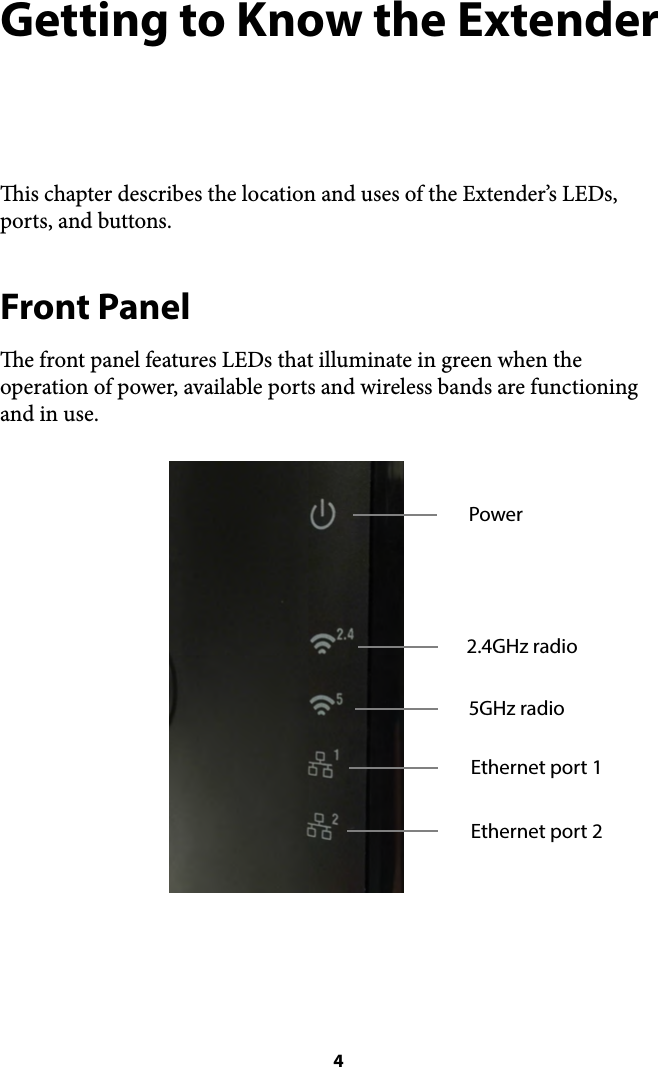
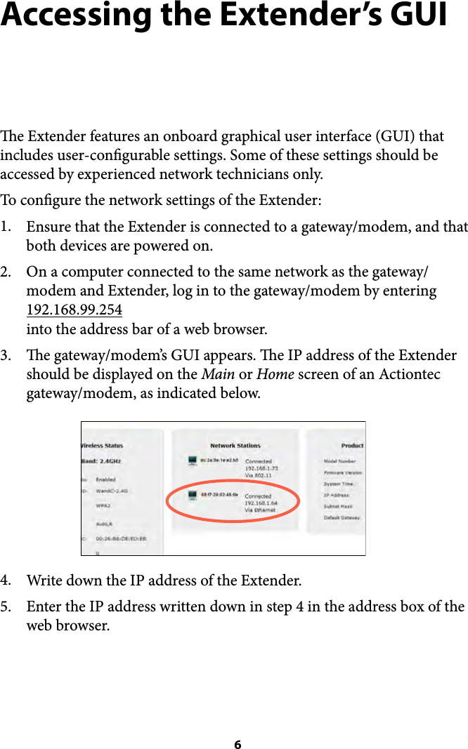
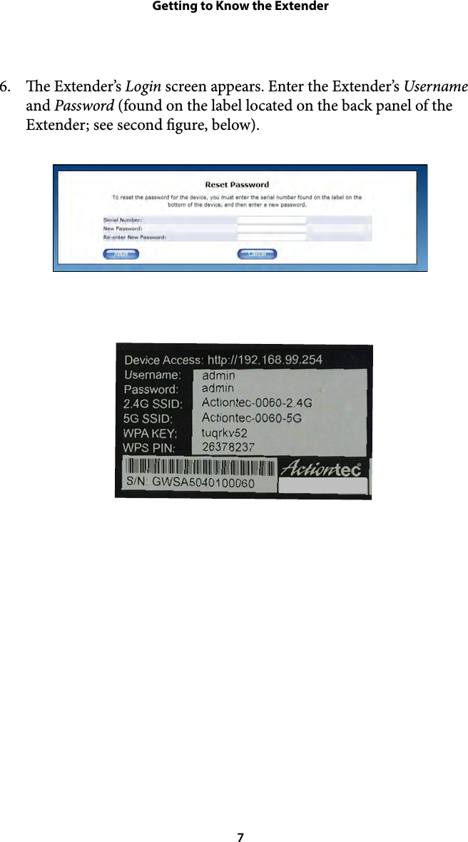
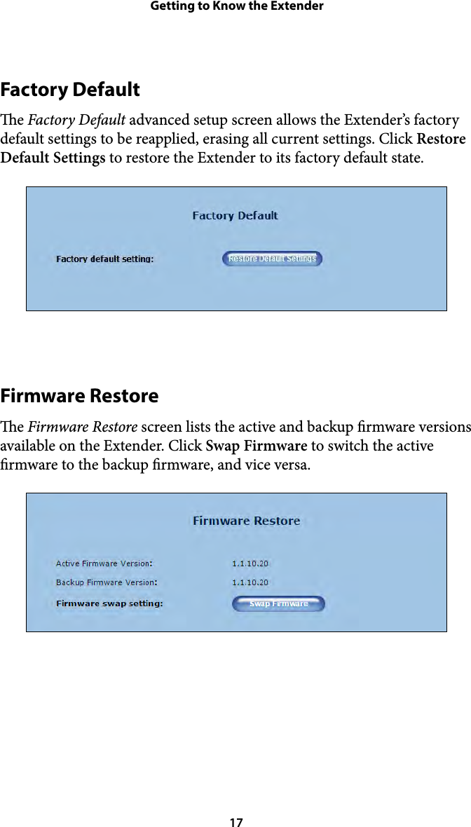
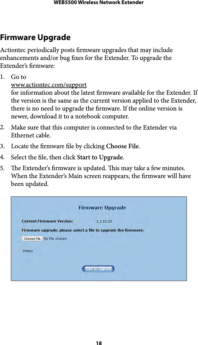
User Manual
Discussion / Help
Navigation