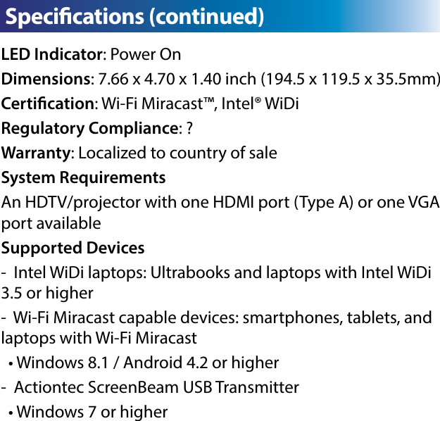
Actiontec Electronics SBWD700A ScreenBeam Enterprise Wireless Display Receiver User Manual

Actiontec Electronics Inc ScreenBeam Enterprise Wireless Display Receiver

User Manual

Mini Wireless Display ReceiverInstallation GuideThis Installation Guide will walk you through the easy steps      to set up your ScreenBeamEnterprise Wireless Display          Receiver. During this process, we’ll show you how to :A Install the ReceiverB1 Connect Using Windows 8.1 or HigherB2 Connect Using Intel WiDi AppB3 Connect Using WiFi Miracast-enabled DeviceC Switch Display ModesD Device ManagementModel# SBWD700APart No:
  Meeting ScreenBeam EnterpriseLED Indicator: indicates power supply statusUSB port: for conguring MGT connection dataVGA In: reservedOn/O: the power switchVGA Out: connects to HDTV/projector with a VGA port for video outputHDMI Out: connects to HDTV/projector with an HDMI port for video and audio outputEthernet: Connects to Ethernet for receiver management with ScreenBeam Central Management SystemReset Button: resets system to defaultsDC IN: for power supply
Welcome!Step2 Plug one end of the HDMI/VGA cable into the HDMI/VGA Out port on the Receiver, and the other end into an available HDMI/VGA port on the HDTV/Projector.Step3 Plug the connector of the power cord into the DC IN port of the Receiver, and the AC adapter into a power outlet. A  Install the ReceiverThank you for your purchase of a ScreenBeam Enterprise Wire-less Display Receiver (hereinafter referred to as the Receiver).  The Receiver connects to your Intel WiDi or Miracast-capable device wirelessly, and displays the device’s screen on your HDTV.Step1 Get the Receiver, power adapter, and HDMI cable or VGA cable from the Receiver’s box.Step4 Press the On/O button to switch the power on. Note: You can switch the receiver o by pressing the On/O button again.
Step5 Turn on your TV and switch the input source until you see the Ready To Connect screen.
B1  Connect Using Windows 8.1 or HigherStep1 From the Windows desktop, navigate to the Charms menu and select Devices. You can also use the shortcut keys,        + K. Step2 From the Charms menu, click the Project icon.The Receiver is now connected to your HDTV. Proceed to one of the next three sections of this Guide (depending on the device you are using to connect to the Receiver) to nish the connection procedure.For Windows 8.1 devices, please proceed to section B1;For Windows 7/8 devices, please proceed to section B2;For Android devices, please proceed to section B3.
Step4 Select the ScreenBeam Receiver from the list.Step5 Enter the PIN provided by your system administrator (or the one displayed on the television screen), then connect and display.Note: If you are running Windows 8.1 and the screens above do not appear, go to http://www.actiontec.com/widi81 for the latest software updates.Step3 From the Project screen, select Add a wireless display.Note: The PIN for connection is “12345670” by default if no PIN is displayed.
Step2 The device scans for  available receivers. Select your re-ceiver on the list and click Connect. (The Connect  Automatically check-box is optional.)Step3 Enter the PIN provided by your system administrator (or the one displayed on the TV screen) on the WiDi device, and then click Continue.Step1Find the Intel Wireless Display application on the device and launch it. To nd the application, go to Windows Search on your device and search for “Intel WiDi” in your apps.B2 Connect Using Intel WiDi AppNote: The default PIN is “12345670”. You can obtain the PIN from your system administrator if no PIN is dis-played on the HDTV.
Step4 The HDTV displays  messages to show the status of the connection process.Step5 A Connection Successful screen appears on your device’s screen, as well as on the HDTV.Display Tip: If the edges of the device screen cannot be seen on the HDTV, adjust cropping. To do this, enter the WiDi application and click Settings. Navigate to the “Picture and Sound” section, click Adjust cropping…, and adjust the HDTV picture by clicking plus (+) or minus (-).Note: Make sure the device supports Intel Wireless Display (WiDi) software version 3.5 or higher. To nd out what version of Intel WiDi your device has, enter the Intel WiDi application and click Help, and then navigate to the “About WiDi” section. To obtain the latest Intel WiDi software and drivers, go to:  http://www.intel.com/go/wirelessdisplayupdate
Step2 The Wireless Display Application scans for available  receivers. Select your receiver from the list.Step3 Enter the PIN provided by your system administrator (or the onedisplayed on the TV screen) if required, and then connect.Step1 On a Miracast-enabled Android device, locate and open the Wireless Display Application.B3 Connect Using Miracast-enabled DeviceYou can connect to the Receiver from a Miracast-enabled  Android device, such as a smartphone, tablet, or game console (nd the wireless display feature in Settings). Also, the device should be running the latest software for best performance. Note: The name of the Wireless Display Application depends on the device type and model. Refer to the device’s carrier or  manufacturer user manual for more details.Note: The default PIN is “12345670”. You can obtain the PIN from your system administrator if no PIN is displayed on the HDTV.
The Receiver supports three display modes when connected with a compatible wireless display application (Intel WiDi or Windows 8.1 Project, for example). In Windows, press the Windows logo + P keys simultaneously      (       + P) to launch the display options and select the desired display mode from the options.           Windows 8.1                                      Windows 7Switch Display Modes
The device management webpage provides the ability to       manage the receiver’s settings. Device ManagementLog into the IT Management ConsoleStep1 Find the receiver’s SSID in the lower left corner of the Ready To Con-nect screen.Step2 Right-click the WiFi network icon on the taskbar of your device and select Open Network and Sharing Center.Step3 The Network and Sharing Cen-ter window appears. Click Set up a new connection or network.Step4 The Set up a new connection or network window appears. Click the Manually connect to a wireless network option.
Device Management (continued)Step5 The Manually connect to a wire-less network window appears. Type in or select the following information.Network name: The SSID of the Screen-Beam receiver you wish to connect to.Security type: WPA2 PersonalEncryption type: AESSecurity key: 12345678 (default)Step6 Check Start this connection automatically if you want to automatically connect to this wireless network when it is in range. Step7 Check Connect even if the network is not broadcast-ing. Click Next.Step8 The receiver’s SSID will be added successfully. Click Close. Your device will connect to the SSID automatically.Step9 An URL (it is “http://192.168.51.1” in this example) is displayed on the connected display.
Device Management (continued) Device Management (continued)Step10 Access the URL address (“http://192.168.51.1” in this example) with a web browser on the laptop.Step11 The web server login interface appears. Type the username and pass-word in the Username and Password boxes and click the Login button. Note:      By default, the Username is “Administrator” and Password is “Actiontec”.     The username and password are case sensitive.Setting up PIN Pairing MethodStep1Go to the Features tab page, and set the Force PIN Pairing on First Connection feature to On or O.
Select “O” to disable the PIN enforcement function. PIN entry or PBC is required when connecting your device to the receiver for the rst time.Select “On” to enable the PIN enforcement function. In this case, you must enter a PIN code on the device connecting to the receiver for the rst time. When this function is en-abled, the system provides two PIN generation methods: Random and Static.Random: A PIN code is generated randomly by the sys-tem and displayed on the connected HDTV/projector.Static: Users can enter seven (7) digits in the Static box, then click the “Apply” button, and the system generates an eight (8) digit PIN and display it on the Static PIN eld. This PIN will not be displayed on the connected HDTV/projector.Step2 Click the “Apply” button to save your settings.Device Management (continued)Setting up PIN Pairing Method (continued)
Device Management (continued)Always On: Selecting this option, the HDMI output is always on.Screensaver: Selecting this option, the system will run the screensaver after the dened idle time expires. Users can dene the idle time (5-9999 seconds) in the Wait time box.HDMI O: Selecting this option, the HDMI output will be turned o after the dened idle time expires. Users can dene the idle time (5-9999 seconds) in the Wait time box.Device Management (continued)Managing HDMI Port OutputStep1Go to the Features tab page, and select the desired option in the HDMI Port Power management drop-down box. There are three options: Always On, Screensaver, and HDMI O.Step2 Click the “Apply” button to save your settings.
Device Management (continued)Modifying the Receiver’s SSIDStep1Go to the Wireless Network Settings tab page, and type a new name in the Network Name (SSID) box and a new password in Network Password box.Step2 Click the “Apply” button to save your settings.Setting up Broadcast LMI BeaconStep1Go to the Wireless Network Settings tab page, and set the Broadcast LMI Beacon feature to Enable or Disable. By default, the Broadcast LMI Beacon feature is disabled.Step2 Click the “Apply” button to save your settings.Note: The receiver’s SSID is not broadcasted when the Broad-cast LMI Beacon function is disabled.
Device Management (continued) Device Management (continued)Modifying the Receiver’s Ethernet SettingsStep1Go  to the Ethernet Interface Setting section on the Ethernet Network Settings tab page, and set the IP Policy to Auto or Static.Step2 Click the “Apply” button to save your settings.Auto: The receiver will be assigned an IP address by the DHCP server.Static: You can dene the IP address, subnet mask, and default gateway for the receiver. If you select Static, you must dene a DNS server.
Device Management (continued)Dening a DNS Server for the ReceiverStep1Go to the Ethernet Interface Setting section on the Ethernet Network Settings tab page, and set the DNS Policy to Auto or Static.Step2 Click the “Apply” button to save your settings.Auto: The receiver will be assigned a DNS server automat-ically.Static: You can dene a DNS server for the receiver.
Device Management (continued) Device Management (continued)Dening the SCMS Server (MGT Server) for the ReceiverStep1Go to the Remote Management Server (MGT) Set-ting section on the Ethernet Network Settings tab page, and dene the MGT Host and the MGT Port.Step2 Click the “Apply” button to save your settings.MGT Host: It is the IP address/host name/domain name of the server that hosts the SCMS server. A DNS server  and a DHCP server are receommended.MGT Port: It is the port number of the SCMS server.
Go to  http://international.actiontec.com/support  for    product support, updates, and more information including:• Firmware Updates   • Troubleshooting   • Registration   • FAQsC  Product Support & Additional InformationC Specications
Language: English, French, German, Italian, Japanese, Simpli-ed Chinese, Traditional Chinese, Russian, and SpanishA/V Interface: HDMI output (Type-A male connector), VGA input, and VGA outputVideo Output: up to full HD 1080p30 (H.264)Audio Output: up to 5.1 surround soundData port: USB 2.0 (Type A)Ethernet: RJ-45, 10/100 MbpsFirmware Upgrade: Wireless upgradeWireless: IEEE 802.11a/b/g/n, dual-band 2.4 GHz and 5 GHzOperation Frequency: 2.4G (2402 MHz – 2480 MHz);             5G (5180 MHz – 5240 MHz, 5725 MHz – 5850 MHz)Antenna Type: PCB antennaWireless Security: WPA2, WPS PIN Pairing, AES 128-bitContent Protection: HDCP 2.xPower Input: 5 V / 2 APower Consumption: < 5 WC Specications
LED Indicator: Power OnDimensions: 7.66 x 4.70 x 1.40 inch (194.5 x 119.5 x 35.5mm)Certication: Wi-Fi Miracast™, Intel® WiDiRegulatory Compliance: ?Warranty: Localized to country of saleSystem RequirementsAn HDTV/projector with one HDMI port (Type A) or one VGA port availableSupported Devices-  Intel WiDi laptops: Ultrabooks and laptops with Intel WiDi 3.5 or higher-  Wi-Fi Miracast capable devices: smartphones, tablets, and laptops with Wi-Fi Miracast  • Windows 8.1 / Android 4.2 or higher-  Actiontec ScreenBeam USB Transmitter  • Windows 7 or higherC  Specications (continued)
 FCC Information and Copyright  This equipment has been tested and found to comply with the limits for a Class B digital device, pursuant to part 15 of the FCC Rules. These limits are designed to provide reasonable protection against harmful interference in a residential installation. This equipment generates, uses and can radiate radio frequency energy and, if not installed and used in accordance with the instructions, may cause harmful interference to radio communications. However, there is no guarantee that interference will not occur in a particular installation. If this equipment does cause harmful interference to radio or television reception, which can be determined by turning the equipment off and on, the user is encouraged to try to correct the interference by one or more of the following measures: —Reorient or relocate the receiving antenna. —Increase the separation between the equipment and receiver. —Connect the equipment into an outlet on a circuit different from that to which the receiver is connected. —Consult the dealer or an experienced radio/TV technician for help.  This device complies with part 15 of the FCC Rules. Operation is subject to the following two conditions: (1)This device may not cause harmful interference, and   (2) this device must accept any interference received, including interference that may cause undesired operation.  changes or modifications not expressly approved by the party responsible for compliance could void the user's authority to operate the equipment.  This equipment complies with FCC radiation exposure limits set forth for an uncontrolled environment .This equipment should be installed and operated with minimum distance 20cm between the radiator& your body.    This transmitter must not be co-located or operating in conjunction with any other antenna or transmitter.  statement:Operations in the 5.15-5.25GHz band are restricted to indoor usage only.

Navigation menu