Actiontec Electronics PK5000 ADSL2+ with 4-Port Ethernet Wireless Gateway User Manual
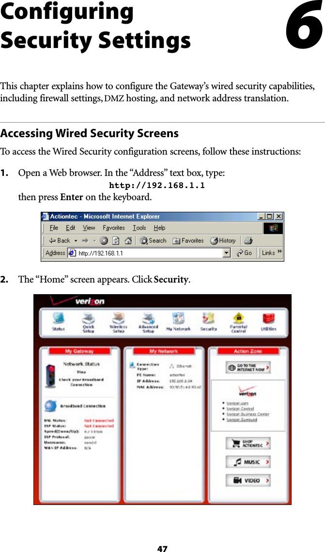
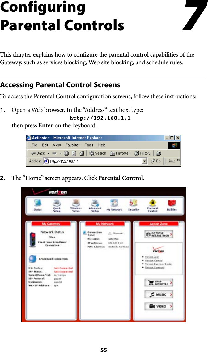
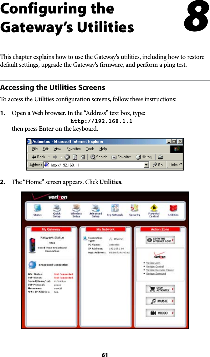
Actiontec Electronics Inc ADSL2+ with 4-Port Ethernet Wireless Gateway
UserManual.wiki
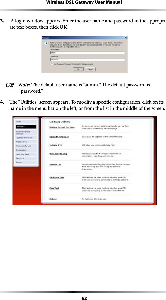
>
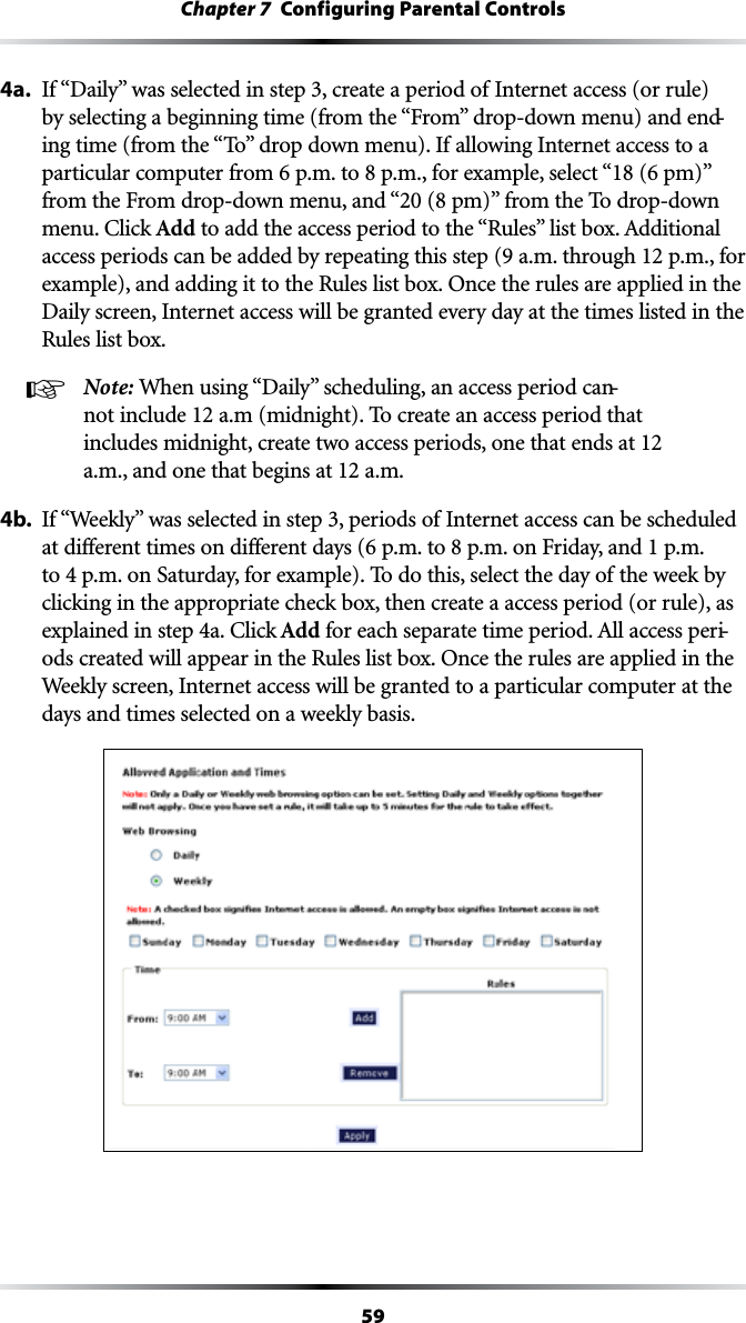
Actiontec Electronics
>
PK5000 User Manual
User Manual
Navigation menu
Upload a User Manual
Namespaces
Wiki Guide
HTML
PDF
Info
Views
User Manual
Discussion / Help
Navigation

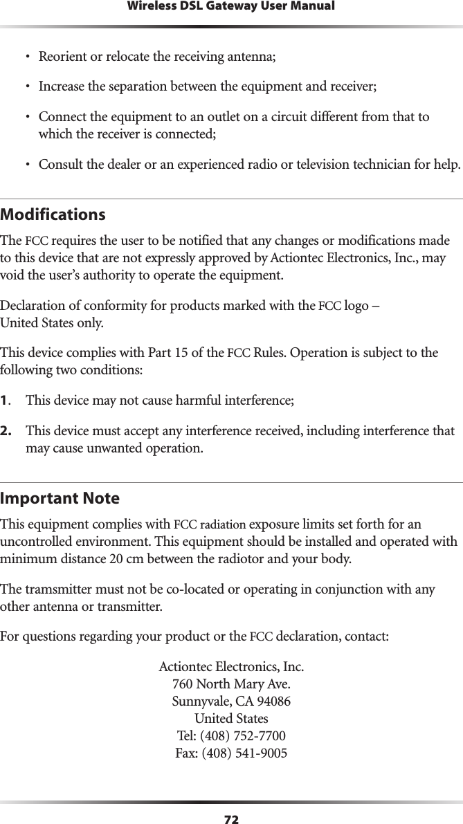
![4Wireless DSL Gateway User ManualUSB LightThe USB light illuminates when the Gateway is connected via its USB port.Wireless Light The Wireless light illuminates when the Gateway is connected wirelessly (if the Gateway’s Wireless feature is turned on).WPS Button The WPS button activates WPS7I&I0ROTECTED3ETUPONTHE'ATEWAY3EECHAPTERh#ONFIGURING7IRELESS3ETTINGSvFORMOREINFORMATIONABOUTWPS.Rear PanelThe rear panel of the Gateway contains seven ports (Ethernet [4], Phone, USB, and Power), as well as Reset and Power switches.Ethernet PortsThe Ethernet ports are used to connect computers to the Gateway via Ethernet cable. The Ethernet ports are 10/100 Mbps auto-sensing ports, and either a straight-through or crossover Ethernet cable can be used when connecting to the ports.DSL PortThe DSL port is used to connect the Gateway to a DSL (Digital Subcriber Line) connection.](https://usermanual.wiki/Actiontec-Electronics/PK5000/User-Guide-1046725-Page-5.png)

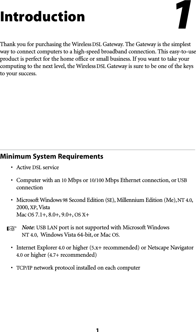
![26Wireless DSL Gateway User ManualWPS (WiFI Protected Setup)7I&I0ROTECTED3ETUP703PROVIDESANEASIERWAYTOSETUPAWIRELESSNETWORKInstead of entering passwords or multiple keys on each wireless client (laptop, printer, external hard drive, etc.), the Router can create a wireless network that only requires pressing buttons (one on the Router, and one on the client [either built-in, or on a compatible wireless card]) to allow wireless clients to join the Router’s wireless network.Activating WPSTo activate WPS on the Router:1. &ROMTHE2OUTERS(OMESCREENCLICKWireless Setup, then select WPS from THEMENUONTHELEFTSIDE4HEh7I&I0ROTECTED3ETUPvSCREENAPPEARS2. !CTIVATE703BYCLICKINGTHEh/NvRADIOBUTTONUNDERh4URN703/.v](https://usermanual.wiki/Actiontec-Electronics/PK5000/User-Guide-1046725-Page-27.png)