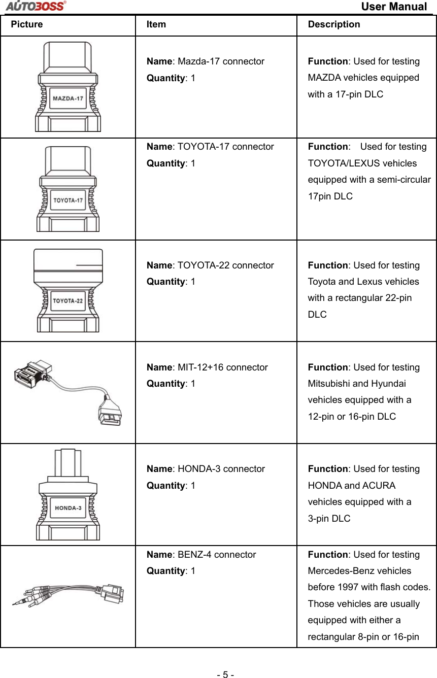
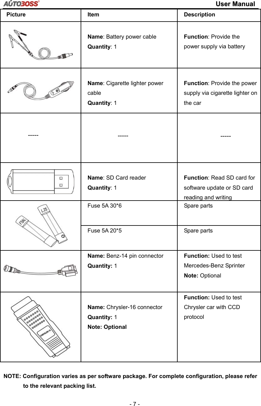
AUTOBOSS TECH V30 Vehicle Diagnostic Computer User Manual V30 Elite UserManual
AUTOBOSS TECH. INC. Vehicle Diagnostic Computer V30 Elite UserManual
UserManual.wiki
>
AUTOBOSS TECH
>
V30 User Manual
User manual
Navigation menu
Upload a User Manual
Namespaces
Wiki Guide
HTML
PDF
Info
Views
User Manual
Discussion / Help
Navigation

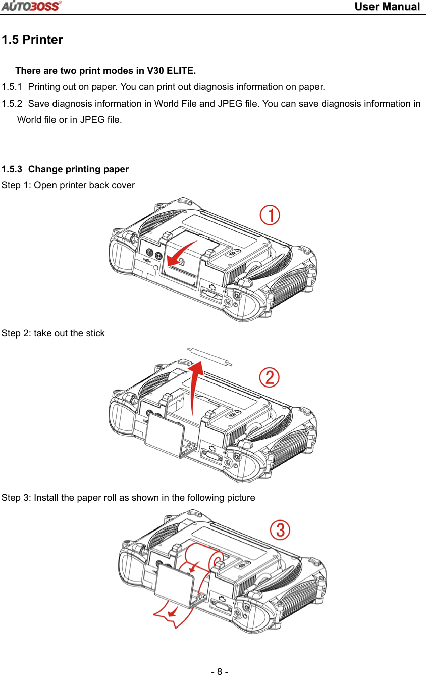
![UUsseerr MMaannuuaall - 10 - 2.2 Interface Instruction 2.2.1 Starting Interface The screen shown on the left picture will appear on the screen after the scanner is switched on. 2.2.2 Touch Screen Calibration Several seconds after power is switched on, the screen will go into calibration mode. Click anywhere on the screen to start calibration if necessary. Note: Just wait for several seconds until the diagnosis program runs if screen calibration is not required. Click the center of cross with touch pen according to the instruction on the screen. Repeat the operation as the cross moves until the setting is finished. After the scanner is started, you will come to the screen shown on the left picture which includes the functions of [Diagnose], [Setting], [User Data], [Version] , [User Manual] and [Special tests Instructions],.](https://usermanual.wiki/AUTOBOSS-TECH/V30/User-Guide-2094987-Page-13.png)
![UUsseerr MMaannuuaall - 11 - 2.2.3 Diagnose Program After entering [Diagnose], you will enter the diagnostic screen where you can select the region of vehicle manufacturer required: China, Europe, Asia, America, Others (OBDⅡ/EOBD) and Favorite. Europe: This section includes the diagnostic programs for European vehicles. Asia: This section includes the diagnostic programs for Asian and Korean vehicles. America: This section includes the diagnostic programs for US vehicles. China: This section includes the diagnostic programs for Chinese vehicles. Others: This diagnostic program can test all vehicles with OBDⅡ/EOBD and CAN-OBD. Favorite: This function enables you to save the vehicle frequently tested. For example, once you save Honda as your favorite, it will lead you directly to Honda interface when you click 【diagnose】 icon. You can save more than one vehicle as your favorites.](https://usermanual.wiki/AUTOBOSS-TECH/V30/User-Guide-2094987-Page-14.png)
![UUsseerr MMaannuuaall - 12 - 2.2.4 System Setting Click the button [Setting] to enter settings for language, time, Self-Check and Print Mode. 2.2.4.1 Language Setting V30 ELITE supports Multilanguage. Choose any language needed under [working language] and press [OK] to finish language setting. 2.2.4.2 Time Setting Click [Set time] to enter the menu for time selection. By clicking on signs of “▼”or“▲”, numbers will increase or decrease correspondingly. Click the button [Set time] to finish setting. The dialog box “Set system time successfully!” will popup. Click [OK] to save the setting or [Cancel] to exit. 2.2.4.3 Display Data Stream in Imperial Data stream will be displayed in Imperial after [Imperial ] is chosen.](https://usermanual.wiki/AUTOBOSS-TECH/V30/User-Guide-2094987-Page-15.png)
![UUsseerr MMaannuuaall - 13 - 2.2.4.4 Self-Check This is for hardware checking. Click the button [Self check] and any hardware faults will be displayed. Please contact technical support if a hardware problem is reported. If there are no hardware errors, the checking result will be “System Self test report: No error found.” 2.2.5 Version Information Click the button [Version] in main menu to get the information of Hardware version, Software Serial number, Release date, etc. Click [Back] to exit. 2.2.6 User Manual Click the Button [User Manual], and you can read the user manual. 2.2.7 Special tests Instructions Click the Button [Special tests Instructions], and special tests, such as Injector code reading, Program new keys, air bleeding and others, will be shown step by step.](https://usermanual.wiki/AUTOBOSS-TECH/V30/User-Guide-2094987-Page-16.png)
![UUsseerr MMaannuuaall - 15 - 2.4 Software Upgrading 2.4.1 Download and Install “V30 ELITE Update Client” Step1: Visit AUTOBOSS website at http://www.AUTOBOSS.net Step2: Enter English website Step3: Click button [Download] and select V30 ELITE as shown in left image. Step4: Click the option [V30 Elite Update Client] to download the update client to your PC. A file named V30 ELITEUpdateClien.exe will be saved in your PC.](https://usermanual.wiki/AUTOBOSS-TECH/V30/User-Guide-2094987-Page-18.png)
![UUsseerr MMaannuuaall - 16 - Step 5: Double click this file to install “V30 ELITE update client” step by step until you see the image shown on the left. Note: Just click the button [Next] in each step during the installation. We advise you to keep everything as default. Please remember to input your name and company name. After finishing the installation, you will see the icon shown below on your desktop Download of “V30 ELITE update client” is finished. 2.4.2 Check V30 ELITE S/N and Password Check the S/N: Please refer to 2.2.7 Version information in this manual; How to get password: Click the button [Activate] to get the original register password as shown in left image.](https://usermanual.wiki/AUTOBOSS-TECH/V30/User-Guide-2094987-Page-19.png)
![UUsseerr MMaannuuaall - 17 - Fig 2-1 Login screen Fig 2-2 Downloads progress 2.4.3 Upgrading Instructions 2.4.3.1 Run V30 ELITE update client program Step1: Take out the SD card from main unit, plug it into the USB SD card reader and connect to PC. Step 2: Double click to run the V30 ELITE update client program on your PC and go to update screen as shown in Fig 2-1. 2.4.3.2 Login the Server (1) Input the serial number and password then click the [OK] button to connect to server. It takes some seconds before the download is finished like Fig 2-2. (2) The default server is ‘www.AUTOBOSS.net’. Normally you do not have to change the server. Note: ① Be sure that both S/N and password are correct. Please pay attention, the letters are case sensitive! ② If login takes a long time because of low internet speed, you can exit and retry; ③ Internet firewall might affect the login. If login fails, please make sure you have an internet connection, and ensure any installed firewall is not blocking the connection to the server. For detailed operation instructions, please contact technical support.](https://usermanual.wiki/AUTOBOSS-TECH/V30/User-Guide-2094987-Page-20.png)
![UUsseerr MMaannuuaall - 18 - Fig 2-3 Program list screen Fig 2-4 Modify password Fig 2-5 Modify password screen (4) After download is finished, all updates available will be displayed as shown in Fig 2-3. (5) The update client will automatically identify new updates available for your V30 ELITE. 2.4.3.3 Modify Password After initial login, users can change original registered password. Operation instruction: (1) After inputting the serial number, click [Modify password] as shown in Fig 2-4 to go to the next step as Fig 2-5. (2) Input the current password and new password, then click [OK] for confirmation. Note: Please keep the password in a secure location. If you forget the password, please contact AUTOBOSS or technical support.](https://usermanual.wiki/AUTOBOSS-TECH/V30/User-Guide-2094987-Page-21.png)
![UUsseerr MMaannuuaall - 19 - Fig2-6 Input customer info screen Fig.2-7 Download screen Fig.2-8 Download screen 2 2.4.3.4 Input Customer Information You must fill in your personal information when you first login to V30 ELITE update client; otherwise you will not be able to download updates. Operation instruction: Click the button [Customer info] after login succeeds. You can see the screen as shown in Fig. 2-6. Input your information to the relevant spaces and click [OK] to save the information. 2.4.3.5 Software Download After user information is saved, you can download the programs needed. Operation instruction: (1) Choose the language version on the top and tick the small box before the relevant program as Fig. 2-7; (2) Click [Download] in right column to enter download status. Note: A maximum of 10 items can be chosen to download simultaneously. (3) The software will be downloaded to your PC hard drive automatically.](https://usermanual.wiki/AUTOBOSS-TECH/V30/User-Guide-2094987-Page-22.png)
![UUsseerr MMaannuuaall - 20 - Fig.2-9 Software installation screen Fig.2-10 software installation screen 2.4.3.6 Update (1) Take out the SD card from V30 ELITE main unit; (2) Put the SD card into SD Card reader; (3) Connect the Card-Reader to PC USB port; (4) Select the SD card driver on the top-right side of software installation screen as shown in Fig.2-9; (5) Click the button [Update], the selected programs already downloaded to your PC hard drive will be installed on SD card automatically. Note: Make sure the update destination is the SD card driver. To confirm this, please enter “My computer” on the PC to verify the content in SD card. 2.4.3.7 Software Management You can delete old versions of software on the SD card by software management. Operation instruction: Click the button [Management] to enter the screen shown in Fig. 2-10. Select the software that is not needed and click [Delete]. The selected software will be uninstalled automatically. 2.4.3.8 Exit After finishing all of the steps, click [Exit] to exit the update client.](https://usermanual.wiki/AUTOBOSS-TECH/V30/User-Guide-2094987-Page-23.png)
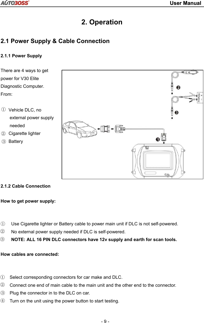
![UUsseerr MMaannuuaall - 23 - 3.Test Procedure 3.1 Engine ECU Testing Methods 3.1.1 Testing Description (1) Power up and turn on the scanner; (2) Click [Diagnose] [Europe] to enter screen as shown on the left image; (3)Select diagnostic program Click [VW], for example, to enter software version selection screen shown in the left image. Note: Program descriptions will be displayed under the version information. (4)Select a version such as V3.1 and click [OK] as shown in left image. Click [Cancel] to go back to the previous menu; (5)Select vehicle type: take Volkswagen/Audi for example, we have two vehicle types for selection: [With Can bus] and [Without Can bus]. Here we choose without Can bus car as an example to introduce the test. NOTE: VEHICLES WITH CAN BUS WILL HAVE DLC PINS 6 AND 14 POPULATED](https://usermanual.wiki/AUTOBOSS-TECH/V30/User-Guide-2094987-Page-26.png)
![UUsseerr MMaannuuaall - 24 - (6) Select system: [Common system Auto-Scan]: Test the common-use ECU automatically; [All system Auto-Scan]: Test all ECU automatically; [Common]: by choosing this item, all common-use ECU will be displayed on the screen, users can then select ECU required accordingly; Other systems: Enter the systems as per relevant ECU type. (7) Click [Common] to enter the screen shown on the left. Select [01-Engine] to enter the screen with the following functions. [01-Interrogate control unit versions] [02-Interrogate fault memory] [03-Final control diagnosis] [04-Introduction of basis setting] [05-Erase fault memory] [06-End output] [07-Coding] [08-Read measuring value block] [09-Read individual measuring value] [10-Adaptation] [11-Login procedure] [15-Write VIN] Note: Functions 04,07,10,15 require knowledge of the systems operation, please use with care.](https://usermanual.wiki/AUTOBOSS-TECH/V30/User-Guide-2094987-Page-27.png)
![UUsseerr MMaannuuaall - 25 - ① [01-Interrogate control unit versions] Click [01-Interrogate control unit versions] to see the information of control unit as shown on the left. Note: Read out old ECU codes with this function when performing ECU coding. ② [02-Interrogate fault memory] To display the DTC saved in the current control unit, click [02-Interrogate fault memory]. Please refer to the left image. ③ [03-Final control diagnosis] Click the button [03-Final control diagnosis] to test relevant actuator automatically as shown on the left image. Click [Active Test] to begin actuator test. ④ [04-Introduction of basis setting] Click the button [04-Introduction of basis setting] for basic setting. Input desired number using the number keys and click the button [OK] to start the basic setting. [Del]: Delete the input numbers; [Left]: Move cursor to left; [Right]: Move cursor to right; [Home]: Move cursor to Home; [End]: Move cursor to End; [Enter]: confirm enters.](https://usermanual.wiki/AUTOBOSS-TECH/V30/User-Guide-2094987-Page-28.png)
![UUsseerr MMaannuuaall - 26 - The window of “Basic setting!” in left image will popup after Basic Setting is done. [Input]: continue to Input number; [Back]: Back to the Function Menu. Note: Under basic setting mode, you can perform solenoid and engine control unit adaptation without starting the engine, or finish λ control process self-adaptation when engine starts. Also you can check faults or ignition timing by connecting or disconnecting λ control. ⑤ [05-Erase fault memory] Click the button [05-Erase fault memory] to erase DTC as shown on the left image. [OK]: Return to the previous menu ⑥ [06-End output] To exit from the diagnostic program, please click [06-End output]. [Yes]: Exit the diagnosis program [No]: Return to the previous menu ⑦ [07-Code control unit] Click [07-Code control unit] to go to screen as shown in the left image. Then input the code and click [OK], the scanner will begin the coding. Click [OK] after coding succeeds. Note: Please only code the ECU after the ECU has been changed or a function has been added (e.g. Cruise control). You can get the code of the old ECU by choosing [01-Interrogate control unit versions], then recode the new ECU accordingly.](https://usermanual.wiki/AUTOBOSS-TECH/V30/User-Guide-2094987-Page-29.png)
![UUsseerr MMaannuuaall - 27 - ⑧ [08-Read measuring value block] Click [08-Read measuring value block] to enter screen shown in left image. Please input the relevant channel number, and click [OK] to read data stream information. Note: For channel definition, please refer to relevant technical manual. The left image is the data stream of Group 01. [Page Up]: See previous group data stream; [Page Down]: See next group data stream; [Waveform]: Review data stream in graph; [Replay]: Review data stream; [Back]: Return to the Function Menu. [Print]: save the current screen to SD card. ⑨ [09-Read individual measuring value] Click [09-Read individual measuring value] to enter the screen shown in the left image. Input the channel number and click [OK] to view the relative data. Click [Read Value], and current value will be displayed. [Input]: Back to the input screen; [Increase]: View the data of next channel number. [Decrease]: View the data of the previous channel number; [Read value]: Read current value; [Back]: Back to function list menu; [Print]: Save the current screen to SD card.](https://usermanual.wiki/AUTOBOSS-TECH/V30/User-Guide-2094987-Page-30.png)
![UUsseerr MMaannuuaall - 28 - ⑩ [10-Adaptation] Click [10-Adaptation] to enter the screen for inputting channel number as shown in left image. Note: Self-adaptation includes: self-study during idle, service reset, IMMO adaptation and so on. You should login first for some of the functions. For login methods, please refer to [11-Login procedure] on page 26. After inputting the relevant channel number, click [OK] to enter the screen as shown in left image. [Input]: Back to the “input number” screen; [Read]: Read the adaptation value of current channel; [Back]: Back to function list screen; [Print]: Save the current screen to SD card. Click the button [Read] to read the adaptation value of current channel. [Input]: Input new adaptation value; [Back]: Back to function list menu. [Print]: Save the current screen to SD card. Click [Input] in enter the “input adaptation value” screen shown on the left. Input the new value and then click the button [Ok] to go to the next step.](https://usermanual.wiki/AUTOBOSS-TECH/V30/User-Guide-2094987-Page-31.png)
![UUsseerr MMaannuuaall - 29 - After inputting the new value, new adaptation value will be displayed on the screen. If no error is found, please click the button [Change] to go to the next step. Last step: Click the button [Save] to save the new adaptation value and go back to the self-adaptation screen. [11-Login procedure] To perform adaptation in some group, login will be needed first. Just click the button [11-Login procedure], input the code number and then click [OK]. Note: Login is required when performing functions such as ECU coding, change channel adaptation and IMMO, etc. [15-Write VIN] Volkswagen/Audi uses the 3rd generation anti-theft technology, if you change engine control unit and instrument cluster at the same time you must rewrite the VIN code. Please click [15-Write VIN] to input the new VIN. [Del]: Delete the input numbers; [Left]: Move cursor to left; [Right]: Move cursor to right; [Home]: Move cursor to Home; [End: Move cursor to End; [Enter]: confirm the information. [Shift]:same with [Caps Lock] + [shift] function on key board](https://usermanual.wiki/AUTOBOSS-TECH/V30/User-Guide-2094987-Page-32.png)