ASSALOY SCYICLS2 Microprocessor Controlled Networked Locks User Manual XX XXXX Exhibit Cover
ASSA ABLOY Inc. Microprocessor Controlled Networked Locks XX XXXX Exhibit Cover
ASSALOY >
Contents
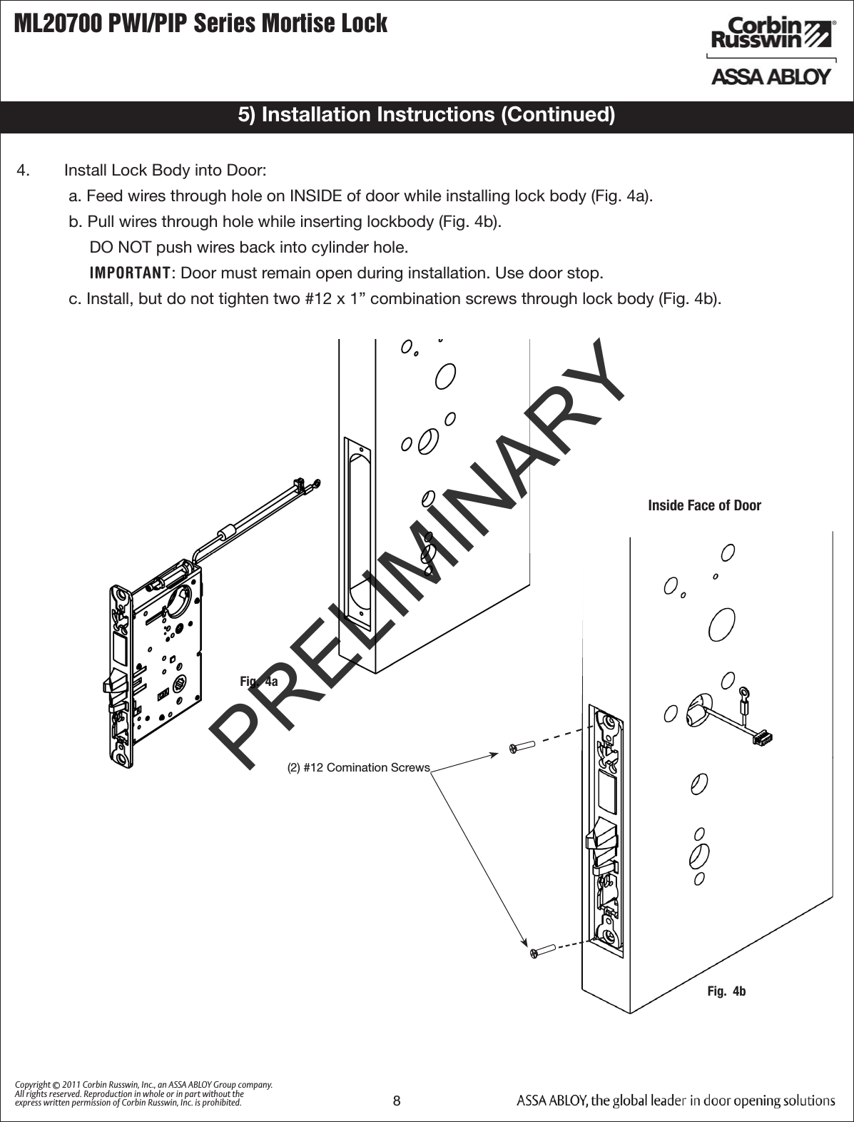
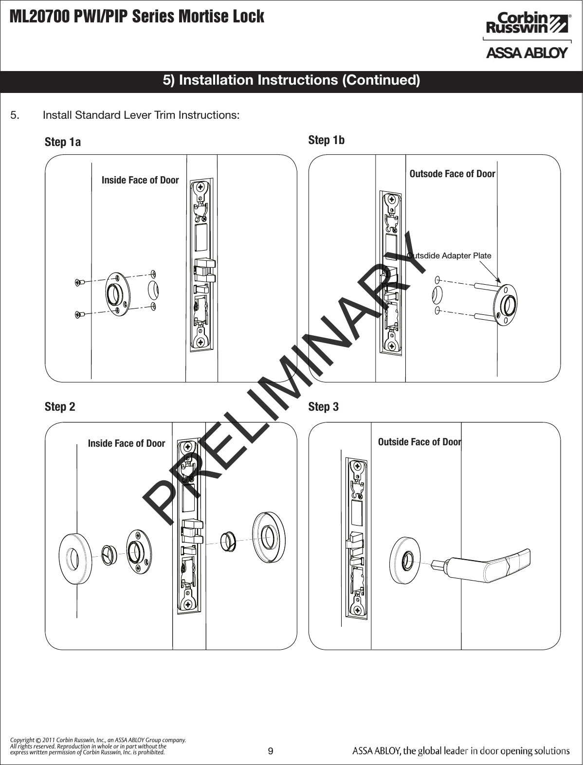
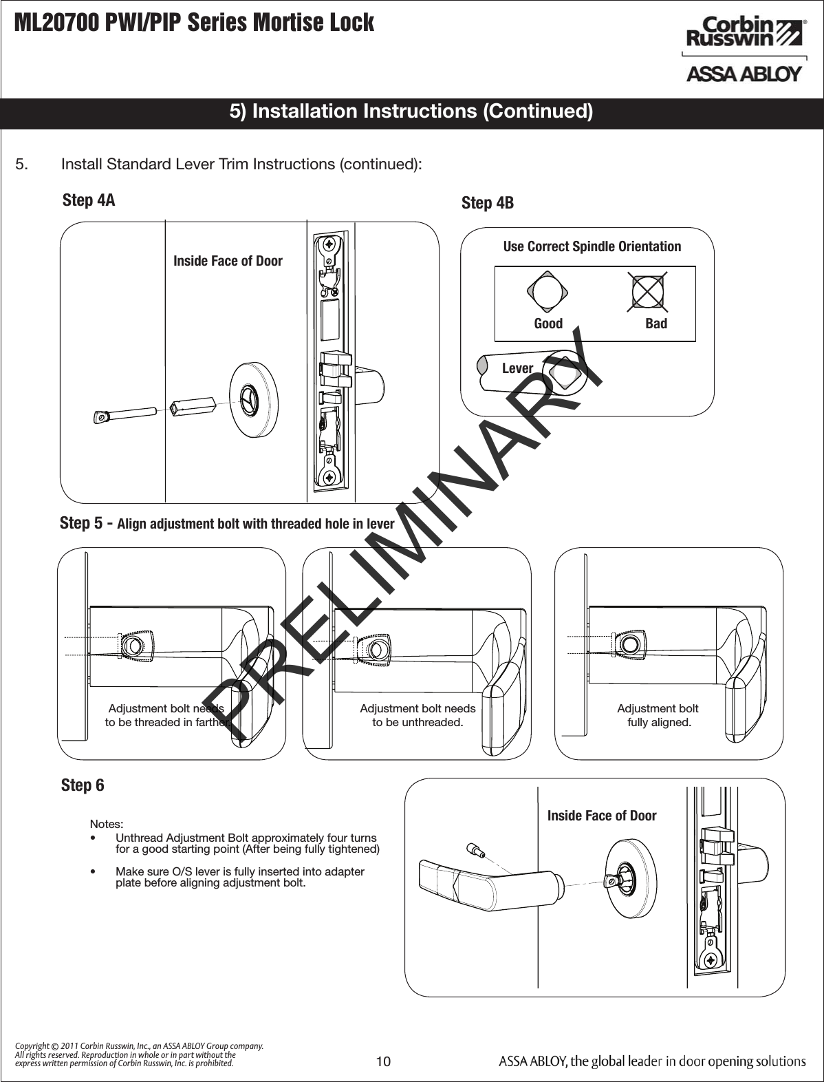
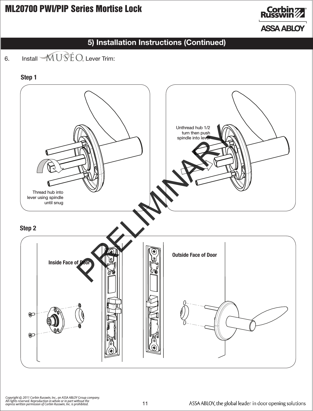
- 1. P1 Manual
- 2. P2 Manual
- 3. TCP Manual
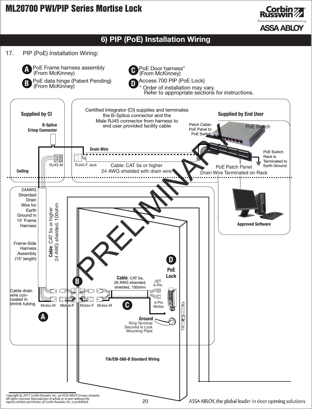
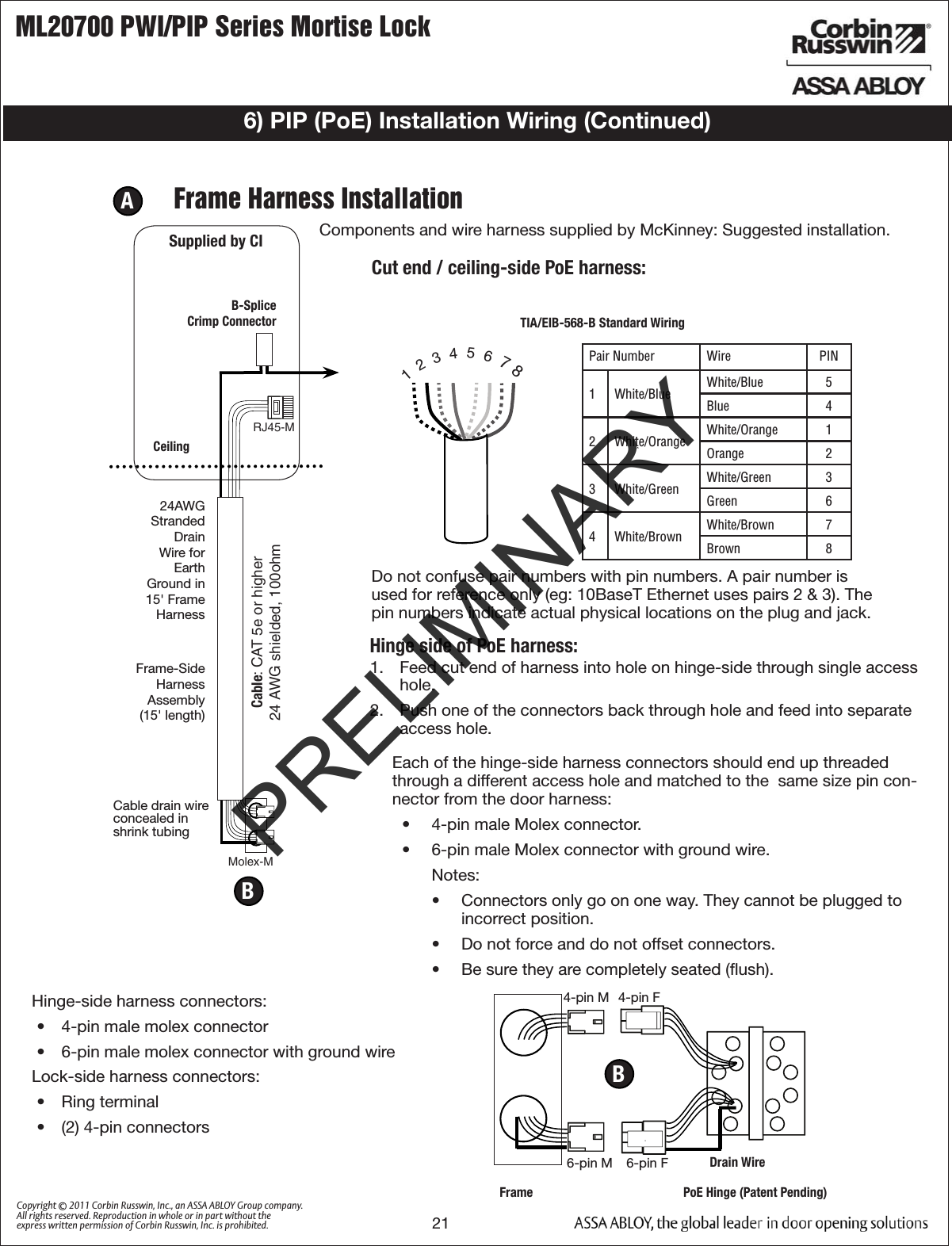
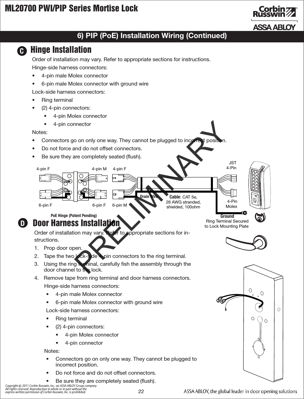
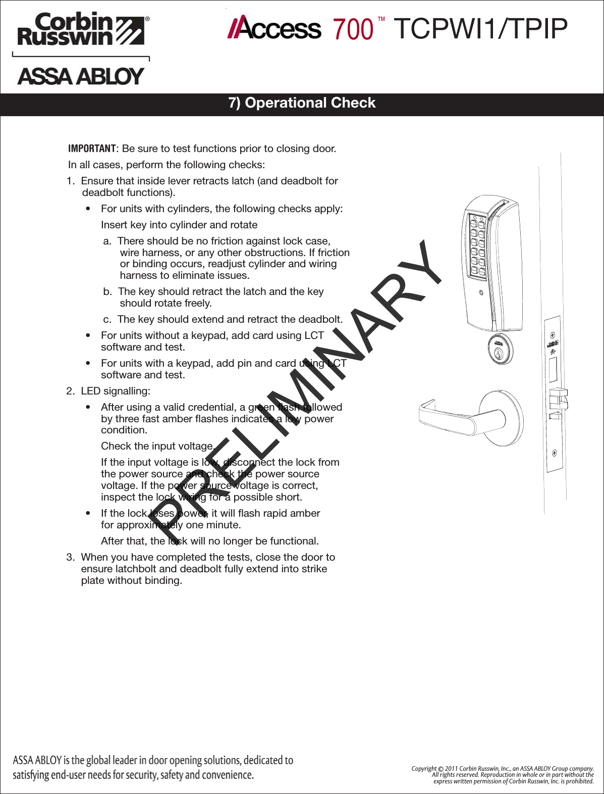
TCP Manual