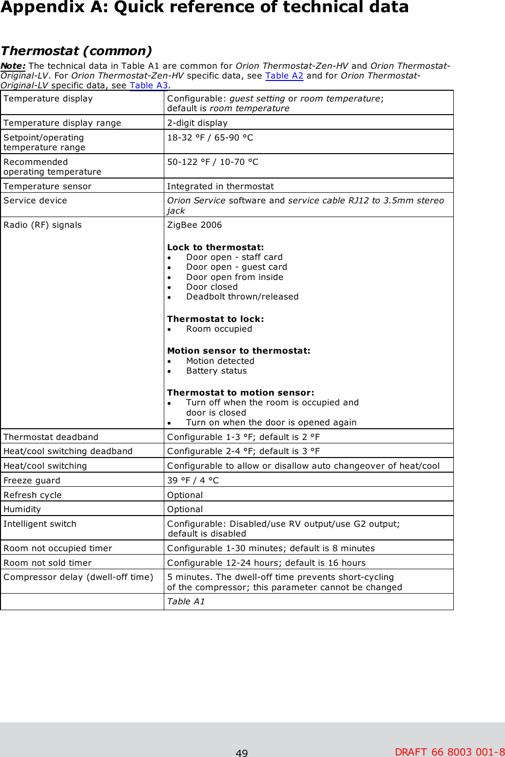
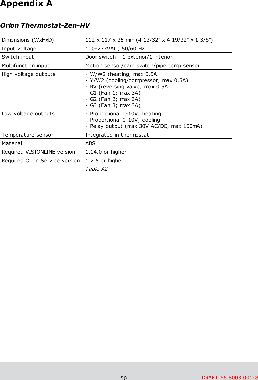
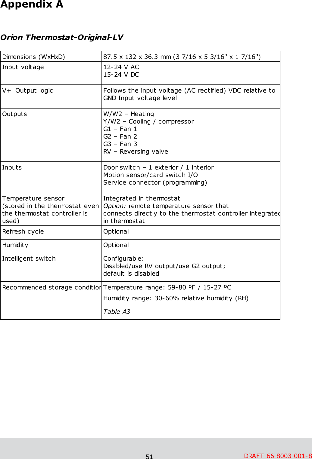
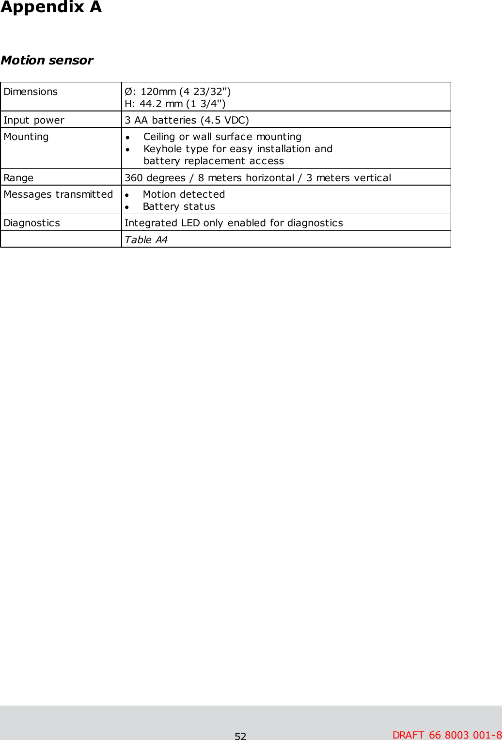
ASSALOY Global Solutions Norway AS TZENHV Thermostat User Manual Enter the help project title here

ASSA ABLOY Hospitality AS Thermostat Enter the help project title here

User Manual

1Daily Use Manual      Orion EMS  DRAFT
2CopyrightsThe information in this document is subject to change at the sole discretion of ASSAABLOY AB without notice.Any use, operation or repair in contravention of this document is at your own risk. ASSAABLOY AB does not assume any responsibility for incidental or consequential damagesarising from the use of this manual.All information and drawings in this document are the property of ASSA ABLOY AB.Unauthorized use and reproduction is prohibited.VingCard is a registered trademark of ASSA ABLOY AB.
3Table of contents....................................................................................................................... 6FCC and IC statements  ..............................................................................................................................................  6FCC statements ..............................................................................................................................................  6Industry Canada statements ....................................................................................................................... 71. Introduction  ..............................................................................................................................................  81.1 Orion EMS devices ..............................................................................................................................................  91.2 Terminology ..............................................................................................................................................  111.3 General about Orion Service ..............................................................................................................................................  111.4 General about alarms ..............................................................................................................................................  121.5 Events and commands ............................................................................................................................................................................................  131.5.1 Thermostat event report ..............................................................................................................................................  141.6 Basic EMS logic ............................................................................................................................................................................................  141.6.1 Room occupied ............................................................................................................................................................................................  141.6.2 Room unoccupied ............................................................................................................................................................................................  151.6.2.1 Door open in 'roomunoccupied' mode............................................................................................................................................................................................  151.6.3 Room unsold ............................................................................................................................................................................................  151.6.3.1 Door open in 'roomunsold' mode............................................................................................................................................................................................  161.6.4 Staff entry ............................................................................................................................................................................................  161.6.4.1 Door monitored by RFdoor switch............................................................................................................................................................................................  161.6.4.2 Door monitored byelectronic lock............................................................................................................................................................................................  161.6.5 Operating states ............................................................................................................................................................................................  161.6.5.1 One interior door............................................................................................................................................................................................  171.6.5.2 One exterior door............................................................................................................................................................................................  171.6.5.3 One exterior and oneinterior door............................................................................................................................................................................................  181.6.6 Thermostat control chart ..............................................................................................................................................  191.7 Orion EMS parameters ............................................................................................................................................................................................  191.7.1 Basic parameters ............................................................................................................................................................................................  211.7.2 Advanced parameters ..............................................................................................................................................  231.8 Operator templates ............................................................................................................................................................................................  241.8.1 Operator template X-reference ..............................................................................................................................................  251.9 Setback override ....................................................................................................................... 262. Thermostat buttons and display  ..............................................................................................................................................  262.1 Orion Thermostat-Zen-HV ............................................................................................................................................................................................  262.1.1 Thermostat buttons ............................................................................................................................................................................................  272.1.2 Thermostat display ..............................................................................................................................................  282.2 Orion Thermostat-Original-LV  ............................................................................................................................................................................................  282.2.1 Thermostat buttons ............................................................................................................................................................................................  292.2.2 Thermostat display
4....................................................................................................................... 313. Energy management summary and alarm list  ..............................................................................................................................................  313.1 Energy management summary ..............................................................................................................................................  333.2 Alarm list ....................................................................................................................... 344. Real time room status  ....................................................................................................................... 355. Thermostats list  ....................................................................................................................... 386. Occupancy report  ....................................................................................................................... 397. Energy statistics report  ....................................................................................................................... 408. Tools/Options  ..............................................................................................................................................  408.1 General ..............................................................................................................................................  418.2 Maintenance ..............................................................................................................................................  418.3 Housekeeping ....................................................................................................................... 429. Orion EMS in SysMon  ..............................................................................................................................................  439.1 Thermostats ..............................................................................................................................................  449.2 Online commands ..............................................................................................................................................  449.3 Broadcasts ..............................................................................................................................................  459.4 Room events ....................................................................................................................... 4610. Maintenance  ..............................................................................................................................................  4610.1 Thermostat (Orion Thermostat-Zen-HV) ............................................................................................................................................................................................  4610.1.1 To disassemble a thermostat ............................................................................................................................................................................................  4710.1.2 To replace a fuse ..............................................................................................................................................  4810.2 Thermostat (Orion Thermostat-Original-LV) ............................................................................................................................................................................................  4810.2.1 To dismount a thermostat ............................................................................................................................................................................................  4810.2.2 To exchange the batteries ....................................................................................................................... 49Appendix A: Quick reference of technical data  ..............................................................................................................................................  49Thermostat (common) ..............................................................................................................................................  50Orion Thermostat-Zen-HV ..............................................................................................................................................  51Orion Thermostat-Original-LV ..............................................................................................................................................  52Motion sensor ....................................................................................................................... 53Appendix B: Troubleshooting  ..............................................................................................................................................  53A/C unit not blowing hot/cold air ..............................................................................................................................................  53Fan speed not working ..............................................................................................................................................  54Thermostat has no power ..............................................................................................................................................  54Room is not going into Occupied state ..............................................................................................................................................  55A/C unit cooling when calling for heat (and vice versa)
5..............................................................................................................................................  55Fan continues to run even when the thermostat is turned off ....................................................................................................................... 56Appendix C: Read more  ....................................................................................................................... 57Revision history
6DRAFT 66 8003 001-8FCC and IC statementsFCC statementsChanges or modifications to the equipment not expressly approved by the partyresponsible for compliance could void the user's authority to operate the equipment. Note: This equipment has been tested and found to comply with the limits for a Class Bdigital device, pursuant to Part 15 of the FCC Rules. These limits are designed to providereasonable protection against harmful interference in a residential installation. Thisequipment generates, uses and can radiate radio frequency energy and, if not installedand used in accordance with the instructions, may cause harmful interference to radiocommunications. However, there is no guarantee that interference will not occur in aparticular installation.If this equipment does cause harmful interference to radio or television reception, whichcan be determined by turning the equipment off and on, the user is encouraged to try tocorrect the interference by one or more of the following measures:Reorient or relocate the receiving antenna.Increase the separation between the equipment and receiver.Connect the equipment into an outlet on a circuit different from that to whichthe receiver is connected.Consult the dealer or an experienced radio/TV technician for help.Industry Canada statements These devices comply with Industry Canada licence-exempt RSS standard(s). Operationis subject to the following two conditions:     (1) these devices may not cause interference, and     (2) these devices must accept any interference, including interference that may          cause undesired operation of the devices.Les présents appareils sont conformes aux CNR d’Industrie Canada applicables auxappareils radio exempts de licence. L’exploitation est autorisée aux deux conditionssuivantes:    (1) les appareils ne doivent pas produire de brouillage, et    (2) l’utilisateur des appareils doit accepter tout brouillage radioélectrique subi,          même si le brouillage est susceptible d’en compromettre le fonctionnement.The term "IC" before the equipment certification number only signifies that theIndustryCanada technical specifications were met.Le terme "IC" devant le numéro de certification signifie seulement que les specificationstechniques Industrie Canada ont été respectées.CAN ICES-3(B) - This Class B digital apparatus complies with Canadian ICES-003.NMB-3 (B) - CET appareil numérique de la classe B est conforme à la norme NMB-003du Canada.
7DRAFT 66 8003 001-81. IntroductionEnergy is a large cost for hotels, and EMS (Energy Management System) is a way of achieving energy savings in guest rooms. With the Orion EMS software option toVISIONLINE it is possible toview the Orion EMS status of different roomsmodify the configurable parameters for a room (or group of rooms/the entire property) provide alarm conditionsprovide energy savings reportsprovide preventative maintenance reportsNote: For mounting of Orion EMS devices, installation of the software option etc, see Installation manual Orion EMS.  A main task for Orion EMS is to determine whether or not a guest room is physicallyoccupied. When a room is not occupied, Orion EMS controls the HVAC (HeatingVentilation and Air Conditioning) systems based on the configurable settings of the system. Note: In the rest of this document, the following applies unless something else is stated:    - the term 'thermostat' includes thermostat as well as thermostat controller    - the information is common for both Orion Thermostat-Zen-HV and       Orion Thermostat-Original-LVNote: For information about what firmware to use in different Orion EMS configurations,see the document Upgrading an RFID lock for an Orion EMS offline scenario.  Note: The best conditions for Orion EMS are obtained if also the locks are online andcommissioned to the same ZigBee network as the thermostat and the motion sensor. Certain Orion EMS operations cause alarms; see chapter Energy management summaryand Alarm list for details. Occupancy status is included in all alarms. This allows the staffto fix the problem that caused the alarm without bothering the guest.
8DRAFT 66 8003 001-81.1 Orion EMS devicesThe devices used together with Orion EMS are:   digital thermostat (two variants: Orion Thermostat-Zen-HV and OrionThermostat-Original-LV)Note: Depending on installation conditions, also a thermostat controller is used or not (only applicable for Orion Thermostat-Original-LV). If it is used, the thermostat controller is the master of the system while a battery operatedthermostat transmits the guest settings to the thermostat controller forprocessing and decision making.motion sensordoor monitoring device; lock, RF door switchNote: It is also possible to use a wired door switch without radio, but this manual mainly describes the RF door switch. For more information about wireddoor switches, see Installation manual Orion EMS.gateway (the same as is used for online doors; requires the Online option)Note: The gateway is not used in offline scenarios.                               Figure 1: Orion EMS example configuration; the thermostat shown in the picture is ofOrion Thermostat-Original-LV type.The thermostat has a built-in ZigBee router via which it communicates to the software andthe devices within the room. The thermostat stores all parameters needed for Orion EMS; if the thermostat controller is used as well, the parameters (with a few exceptions; see Installation manual Orion EMS for details) are instead stored in the thermostat controller.The parameters are either transferred online from the software or from the Orion Servicesoftware; see Quick reference guide Orion Service for more information about the latter. Note: For each room number, it is possible to have eitherone wired thermostatup to five motion sensorsup to five door switchesOR one thermostat controller up to five battery thermostats up to five motion sensorsup to five door switches
9DRAFT 66 8003 001-81.2 TerminologyDeadbandThe range the temperature is allowed to drift before the heat or air conditioner is turned onDefault setpointDefault setpoint is the temperature which the thermostat is setto until a guest changes the temperature. The thermostat willalso return to the default setpoint after guest check-out.  Dynamic setbackThe dynamic setback temperatures are configured as a set number of degrees above or below the guest setting. For example, if the guest setting is 68 ºF (20 ºC) and theunoccupied setback is configured to 7 ºF (4 ºC) above the guest setting, the system will allow the temperature to drift to 75 ºF (24 ºC) when the room is unoccupied.EMSEnergy Management SystemExterior door timeoutThe time that will pass before the HVAC is turned off after an exterior door is left openFCU Fan Coil UnitFreeze guardIf the temperature in any room with a thermostat goes below 39 ºF (4 ºC), there will be an alarm and the HVAC will start heating.HVACHeating Ventilation and Air ConditioningIntelligent switchThe intelligent switch is an output for lighting control which works according to the occupancy status. The availablealternatives forintelligent switch aredisabled; defaultuse RV outputuse G2 outputIf intelligent switch is applicable, normally 'Use RV output' should be marked unless the air handler is a heat pump. In the latter case, mark 'Use G2 output' instead. Motion sensorA device that detects a person's movement in an areaOccupiedSomeone is physically in the room; see section Room occupied for more informationOccupied limitsLimits the Set temperature range, i.e. the temperature which the guest can set the thermostat toPTAC (Package Terminal Air Conditioner)A PTAC is a fully self contained system that is typically located on the exterior wall of a hotel room. These units come in standard control or heat pump models.  Pre-condition timeNumber of hours the thermostat shall run at the default setpointafter check-in. If no entry has been done when this time expires, the unoccupied setback will be assumed. The pre- condition time can be 1-12 hours or 'disabled' (default is 2 hours).
10 DRAFT 66 8003 001-8Pulse lengthThe welcome scene can be set up to have a pulse length:0 = welcome scene always off Chosen length in the interval 1-255 secondsRefresh cycleThe Orion EMS system can, in setback control, run the A/C unitevery 25 minutes for a period of 2 minutes to re-circulate the air in the room; the optional function is only for cooling mode. SetbackThe temperature the room is allowed to drift to when the room is unoccupied. Also see dynamic setback and static setback.Setback overrideThe Orion EMS features can be overridden until the room is unsold again, or until a certain time. If desired, the time can be set far ahead so that the setback override is in practice until further notice.  SetpointThe temperature which the guest has set on the thermostat.Static setbackThe static setback temperatures are configured in the system and do not change based on the guest settings. For example, if the unoccupied upper setback temperature is 79 ºF (26 ºC),the system will allow the temperature to drift to 79 ºF (26 ºC)when the room is unoccupied regardless of the thermostat setting (this example assumes that it is summertime) when the room becomes unoccupied. As soon as the guest returns to the room, the temperature is returned to the guest setting. UnoccupiedNo one is physically in the room although the room may be currently rented; see section Room unoccupied for more information.UnsoldThe room is not currently rented and no one is in the room. In this case, a deeper setback is implemented for greater energy savings. See section Room unsold for more information. Welcome sceneIf desired, it is possible to have a welcome scene which it isactivated when the occupancy state for a room changes fromunsold to unoccupied. The available alternatives for welcome scene are (default is 'disabled'):disabled use RV outputuse G2 outputuse solid state relay**) Only applicable for Orion Thermostat-Zen-HV                                                                    Table 1
11 DRAFT 66 8003 001-81.3 General about Orion ServiceA service device and the software Orion Service are used for initializing thermostats (setting room number and loading configurable parameters)commissioning the thermostat and the motion sensor in the network so themessages are routed correctlyretrieving and displaying the event log from the thermostatupgrading module firmware in thermostat and motion sensorperforming diagnostic operations, e.g.-simulating inputs - e.g. door switch, motion/temperature-reading out status of thermostat (the status of the motion sensor is also shown)-showing the output to the HVAC-making a functionality test including fast clock mode; the thermostat will raise the time one minute per second to test e.g. the room not occupied timerSee Quick reference guide Orion Service for more information about how the aboveoperations are performed. 1.4 General about alarmsAll Orion EMS alarms are shown in the dialog Energy management summary; seechapter 3 for more information. In addition, they are shown in the alarm list. Unless Orion EMS is installed as a separate client, the alarm list will also show other types ofalarms not related to Orion EMS, e.g. housekeeping failed.If the Communication option is set in the software, notifications about Orion EMS alarmscan be sent via e-mail or SMS and reports can be sent by e-mail. The reports that canbe sent concern e.g.energy savings preventative maintenance schedulesoccupancy (the report shows the number of occupied rooms each night; a room isregarded as occupied for the night if it is physically occupied and there is at leastfour hours of occupancy between 8 PM and 6 AM) occupancy trend (the report is combined with the energy savings report andshows occupancy during each time of the day; it is also possible to make as anaverage for a longer period)battery warningsevents for a selected roomoffline roomsThese reports are sent via e-mail at the selected period to users that have been set up in the user notification list of the software to receive the reports; see Installationinstruction Communication option for further information.
12 DRAFT 66 8003 001-81.5 Events and commandsTo the guest, the thermostat appears and operates as a standard digital thermostat;however, this device also receives entry and exit information from the door lock orswitch as well as motion detected information from the motion sensor. This information is used to determine the occupancy status of the room and implement energy savingsstrategy based on this information. In order for the locks to send door events to the thermostats, EMI events must beenabled. This is achieved by presenting an Enable EMI events card at each lock. The card is one of the ZigBee configuration cards that can be issued in VISIONLINE; see Installation manual Orion EMS for details. The following events are sent to thethermostat from the motion sensor:motion detectedbattery status If the lock is online, the following events are sent to the thermostat from the lock: door open – staff carddoor open – guest card; includes check-out date/time, suite rooms and first time usedoor open from insidedoor closeddeadbolt thrown/releasedThe thermostat stores the 75 latest events in a log. Note: In addition to the relevantevents from the lock to the thermostat, additional events are sent from the lock to the hotel system. There are also commands sent from the thermostat to the lock (if online) and the motion sensor:to the lock: the optional auto-DND, which functions as privacy;  no staff cards will be able to open the door (only guest cards and emergency cards will open)to the motion sensor: to turn off the motion sensor when the room is occupied and the door is closed, and to turn on the motion sensor again when the door is opened Note: The commands from the thermostat to lock and motion sensor are not logged as events.
13 DRAFT 66 8003 001-81.5.1 Thermostat event reportThe thermostat event report shows all events that have been sent online from thethermostats or been transferred to the server via Orion Service; see Quick referenceguide Orion Service for details. The housekeeping function keeps the list size limited by removing events that are older than a user defined number of days (default 7 days). To look at a thermostat event report:1. Double click on Thermostat events under the Reports tab in the navigation window. 2. Enter the applicable search filter(s) under the tabs Events, Door or Miscellaneous(see more information below) before pressing the Enter key or clicking OK. Note: At least one of the following requirements must be met:    - a room is selected    - one or two event sub groups are selected3. It is also possible to reload a previous search filter: click the Load… button inthe Events - Search filter dialog, browse to the desired file, mark it and clickOpen. If you want to save a search filter for future searches: click the Save…button, browse to where you want to save the file, give it a name and click Save. If the filter should be shown under Custom in the Reports tab, it must be saved in any of the following locations:           - the folder ’Custom Reports’ in the software installation folder                  - the public documents folder            - the documents folder  The search filters that can be applied on thermostat events are:Events – with this filter you can pick out a specific event, or certain types of events. The main types are Status Changed andAlert. Within each main type, there are event sub groups which can be divided further into specific events. Ifneeded, use the Check all/Uncheck all buttons atthe bottom of the dialog. Figure 2Door – with this filter you can pick out events for a certain room. Click the plus sign to expand a door area and mark the applicable door. Figure 3Miscellaneous – with this filter you can pick out events from certain event dates.Figure 4
14 DRAFT 66 8003 001-81.6 Basic EMS logicThe thermostat along with the motion sensor, lock and/or RF door switches, monitors the occupancy state of the room and operates based on this information. When the room is occupied, the guest is given control and can set the desired temperature. The thermostat will then heat or cool the room as necessary to meet the guest setting.When the room is not occupied, the thermostat will operate based on the configurableparameters of the system. The three occupancy states are occupied, unoccupied and unsold. The following events are considered as in-room events: motiondeadbolt engagedthermostat key pressed1.6.1 Room occupiedWhen the room is occupied, control of the HVAC system is given to the guest. The guest sets the desired temperature and the HVAC system will control the roombased on this setting. The Orion thermostat will enter the occupied state only when the door is closed and in-room events are detected (motion, deadbolt engaged, thermostat key pressed). At this point, the guest has full control of the room temperature.Note: 'Occupied limits' may be used to restrict the guest setting limits. 1.6.2 Room unoccupiedWhen the room is not occupied, the energy management logic takes control of the room based on the configurable parameters of the system. The system will set back the temperature to the unoccupied setting. The system has both an upper setback anda lower setback. The unoccupied setbacks may be static or dynamic; for unsold rooms,only a static setback is used. See section Terminology for more information about staticand dynamic setback.The thermostat will enter the unoccupied state upon the door opening or closing. If no in-room event such as motion is detected, the thermostat will remain in the unoccupiedmode. The thermostat will continue to operate at the guest setting for the duration of theconfigurable 'Room not occupied' timer, at which point it maintains the room temperaturebased on the unoccupied setback temperatures.
15 DRAFT 66 8003 001-81.6.2.1 Door open in 'room unoccupied' modeIf the door is left open, the occupancy state will remain as unoccupied regardless ofwhether or not motion or another in-room event is detected. There is however also a run state in the thermostat which is based on the set-point/guest setting. The run state works differently depending on whether the open door is interior or exterior, seedetails below.   If the open door is configured as an interior door (i.e., opens to another air conditionedspace), the thermostat will operate based on the guest setting as long as motion oranother in-room event is detected. Each time an in-room event is detected, the ‘Room not occupied’ timer will restart. If the ‘Room not occupied’ timer elapses withoutmotion or another in-room event being detected, the thermostat will maintain the roomtemperature based on the unoccupied setback temperatures.If the open door is an exterior door (i.e., opens to a non-climate controlled space), thethermostat will turn off after the ‘Room not occupied’ timer expires regardless of whether or not motion is detected.  Note: If the exterior door timeout is set to ‘Short’, the thermostat will turn off the airhandler after 20 seconds. See chapter 4 Thermostat profiles list, section Under theTimeout tab, for details about setting the exterior door timeout. 1.6.3 Room unsoldWhen the room is not rented, the setback is – to achieve more energy savings – deeperthan when the room is rented but unoccupied. The system will enter the unsold settingwhen the room has been unoccupied for the duration of the configurable ’Room not sold’timer. In the unsold mode, the temperature is based on the unsold setbacktemperatures.  Note: If using an online system, the room will immediately enter the unsold mode uponreceiving a check-out command from the property management system (PMS) or at guest card expiration.  Note:The unsold mode gives the greatest potential for energy savings. For this reason,the online system allows for maximum energy savings as the room does not need to waituntil the ‘Room not sold’ timer elapses to enter the deep setback mode.1.6.3.1 Door open in 'room unsold' mode Similar to the door open condition in the unoccupied state, the thermostat will controlthe temperature based on the guest setting when an interior door is open and motion (or any other in-room event) is detected for a period of time equal to the ‘Room notoccupied’ timer. If the timer elapses with no further detection of in-room events, the thermostat will revert to maintaining the room temperature at the unsold setback. If an exterior door is left open, the thermostat will turn the air handler off.
16 DRAFT 66 8003 001-81.6.4 Staff entryIn order to maximize energy savings, certain considerations must be taken into accountwhen staff members enter the room.  1.6.4.1 Door monitored by RF door switchIf the position of the door is monitored by an RF door switch, the staff member mustleave the door open to avoid interrupting the ‘Room not sold’ timer. If the staff memberallows the door to close, the room will enter the occupied state upon motion detection.As long as the door is left open, the ‘Room not sold’ timer will not be reset.1.6.4.2 Door monitored by electronic lockIf the door position is monitored by the electronic lock and a staff key unlocks the door,the room will not enter the occupied state even if motion is detected while the door isclosed. However, if a thermostat key is pressed or the deadbolt is engaged while thedoor is closed, the room will enter the occupied state.   Note: If a staff member lets a guest into a room with the door position monitored by anelectronic lock, the room will remain unoccupied until the deadbolt is engaged or a buttonon the thermostat is pressed.1.6.5 Operating statesThe following series of tables shows the operation of the system in various scenarios.  Note: The scenarios consider that the unoccupied (or exterior door open) timers haveexpired if applicable.1.6.5.1 One interior doorDoorIn-room Event(Motion/Thermostat KeyPressed/Deadbolt Engaged)HVACStateClosedYesPer guest settingOccupiedOpenYesPer guest setting if opened byguest.  Setback if opened bystaff. If no lock interface, perguest setting.Unoccupied or UnsoldClosedNoSetbackUnoccupied or UnsoldOpenNoSetbackUnoccupied or UnsoldTable 2
17 DRAFT 66 8003 001-8                                                                                                                                                                                                                                                            1.6.5.2 One exterior doorDoorIn-room Event(Motion/Thermostat KeyPressed/Deadbolt Engaged)HVACStateClosedYesPer guest settingOccupiedOpenYesOFF (20 seconds or standard unoccupied time)Unoccupied or UnsoldClosedNoSetbackUnoccupied or UnsoldOpenNoOFF (20 seconds or standard unoccupied time)Unoccupied or UnsoldTable 3                                                                                                                                                                                                                                                                  1.6.5.3 One exterior and one interior doorInterior DoorExterior DoorMotionHVACStateClosedClosedYesPer guest settingOccupiedOpenClosed YesPer guest settingUnoccupied or UnsoldClosedOpenYesOFF Unoccupied or unsoldOpenOpenYesOFFUnoccupied or UnsoldClosedClosedNoSetbackUnoccupied or UnsoldOpenClosedNoSetbackUnoccupied or UnsoldClosedOpenNoOFFUnoccupied or UnsoldOpenOpenNoOFFUnoccupied or UnsoldTable 4
18 DRAFT 66 8003 001-81.6.6 Thermostat control chartFigure 5The thermostat control can be illustrated in a control chart, see example above. If the temperature drifts above the setpoint or setback (depending on occupancymode), the HVAC starts in cooling mode. The thermostat deadband is in this case 2 ºF, so when the temperature is within2 ºF from the setpoint the HVAC is off (from 0 to 2 in the picture). If the temperature continues to rise, the thermostat output for ‘Fan 1/Low’ is triggered, then the output for ‘Fan 2/Medium’ and finally the output for ‘Fan 3/High’.  If the temperature starts dropping, the HVAC then switches to heating mode.There is however a heat/cool switch deadband which in this example is 3 ºF, so the temperature is allowed to drift  3 ºF  from the setpoint before the HVACswitches from cooling mode to heating mode. From 0 to -3 in the picture theHVAC is off; the output for ‘Fan 1/Low’ is therefore not triggered, since this would have been at -2. If the temperature continues to drop, first the output for ‘Fan 2/Medium’ istriggered and then the output for ‘Fan 3/High’.The Orion EMS devices strive towards different temperatures depending on if the roomis occupied, unoccupied or unsold. For ‘occupied mode’ the goal is the setpoint, i.e. the temperature which the guesthas set on the thermostat. For ‘unoccupied mode’ the temperature drifts to the unoccupied setback, which can be static or dynamic. For ‘unsold mode’ the temperature drifts to the unsold setback.
19 DRAFT 66 8003 001-81.7 Orion EMS parametersThere is a number of Orion EMS parameters whose values can be modified in thesoftware. Different operator templates can be given different authorities to modify the parameters. Some parameters are considered as basic and some as advanced. Note: In the parameter column below, it is also stated in what software dialog theparameter is found.Note: The parameter dwell-off time is a setting that will guard against short-cycling and its value is always 5 minutes. The parameter is not visible in the software andcannot be changed, not even by the distributor. 1.7.1 Basic parametersParameterDescriptionAvailable choicesDefault settingFan control(Thermostat profile details dialog, Fanalternative)The thermostat has a buttonwhich allows the user to select from up to three fan speeds, or to choose‘Automatic’ (AUTO) if thethermostat should determine the appropriate fan setting. Note: The ability to control fan speeds depends on thecapability of the air handler, as some systems do not havethree fan speeds.Auto/manualMax fan cool (low, mid, high)Max fan heat (low, mid, high)ManualHighHighFan on when satisfied(Thermostat profile details dialog, Fanalternative)When enabled, the low fanspeed will continue to run even when the setpoint hasbeen reached. This only applies to an occupied room. Enable/disableDisableHVAC control(Thermostat profile details dialog, HVAC/Heating and Coolingrespectively)See available choices to theright. 'Heat pump reversed valve(Type B)' means that thereversing valve output is onwhen heating.'Heat pump reversed valve(Type O)' means that thereversing valve output is offwhen heating.For 'HVAC heating' and'HVAC cooling':n/a4-pipe fan coil2-pipe fan coil2-pipe fan coil withautomatic switchingProportional*Floating valve* For 'HVAC heating' only:Heat pump reversedvalve (Type B)For 'HVAC cooling' only:Heat pump reversedvalve (Type O)*) Only applicable for Orion Thermostat-Zen-HVn/a
20 DRAFT 66 8003 001-8Unoccupied setbacks (Thermostat profile details dialog, Limitsalternative)The applicable number ofdegrees as upper limit andlower limit for setback if a room is unoccupied.Static/dynamic Static upper (72-90 ºF)Static lower(55-70 ºF)If ‘Dynamic’ is chosen:Dynamic upper(2-8 ºF offset)Dynamic lower(2-8 ºF offset)Static78 ºF68 ºF4 ºF4 ºFUnsold setback (Thermostat profiledetails dialog, Limitsalternative)The applicable number ofdegrees as upper limit andlower limit for setback if a room is unsold.Summer(74-90 ºF)Winter(55-70 ºF)84 ºF64 ºFOccupied limits(Thermostat profiledetails dialog, Limitsalternative)With this parameter, it ispossible to limit the allowedtemperature range when the room is occupied. If this is the case, mark the checkbox 'Use occupied limits'and enter the values for upperlimit and lower limit. On/offUpper limit(75-90 ºF)Lower limit(62-72 ºF)Off84 ºF68 ºFExterior door timeout(Thermostat profiledetails dialog, Timeout alternative)If the exterior door is open and the default 'Normal' is used, the HVAC will -regardless of room occupancystatus - turn off after thenumber of minutes entered at 'Room not occupied'. Default is 8 minutes; see Room notoccupied timer in the advanced parameters tablebelow. If the exterior door isopen and 'Short' is used, theHVAC will turn off after 20seconds.Normal/shortNormalFreeze guard(Thermostat profiledetails dialog, Miscalternative)There will be an alarm and the HVAC will start heating if the temperature in any room with thermostat goesbelow 39 ºF (4 ºC). Enable/disableEnableRefresh cycle(Thermostat profiledetails dialog, Miscalternative)The Orion EMS system can in setback control run the A/Cunit every 25 minutes for aperiod of 2 minutes to re-circulate the air in the room;this optional function is only for cooling mode. Enable/disableDisableTemperature display(Thermostat profiledetails dialog, Miscalternative)The thermostat will show either the room temperature or the temperature that hasbeen set by the guest.Room temperature/set temperatureRoom temperatureTable 5
21 DRAFT 66 8003 001-81.7.2 Advanced parametersParameterDescriptionAvailable choicesDefault settingRoom not occupied timer(Thermostat profile detailsdialog, Timeout alternative)This is the amount of time the thermostat maintains the guest setting after the room has entered the unoccupied state.    1-30 minutes8 minutesRoom not sold timer(Thermostat profile detailsdialog, Timeout alternative)When the room has been unoccupied for thisnumber of hours, it will enter unsold mode.    12-24 hours16 hoursThermostat deadband(Thermostat profile detailsdialog, Deadband alternative)The range the temperature is allowed to drift from thesetpoint before the heat or air conditioner is turned on1-3 ºF2 ºFHeat/cool switch deadband(Thermostat profile detailsdialog, Deadband alternative)This parameter is onlyapplicable if auto switchingmode has been chosen under the HVAC tab in the Thermostat profiledetails dialog.The heat/cool switchdeadband is the range thetemperature is allowed to drift before switching fromheat to cool or cool to heat.2-4 ºF3 ºFMax HVAC runtime(Tools/Options dialog, expand Energy managementand choose General)An alarm is triggered if a HVAC runs this longwithout turning off. 30-300 minutes120 minutesMax setback override (Tools/Options dialog, expand Energy managementand choose General)The Orion EMS features may be overridden whenneeded, e.g. for VIP guestswhere no setbacks shouldapply; click here for details. If a number of hours isentered at 'Max setbackoverride', an alarm will be triggered if the setbackoverride exceeds thisnumber of hours. If thedefault 0 hours is used, no alarm will be triggered.0-99 hours 0 hoursMaintenance intervals (Tools/Options dialog, expand Energy managementand choose Maintenance)Number of hours before the threedifferent maintenancealarms should betriggered; the valid range is 0-65 535 hours. - Maintenance counter 1 is for fan time/total
22 DRAFT 66 8003 001-8HVAC time- Maintenance counter 2   is for 'cooling'-  Maintenance counter 3    is for 'cooling or heating' Names for the threemaintenance alarms.   Humidity control(Thermostat profile detailsdialog, Misc alternative)When the humidity controloption is checked, thethermostat will implementcontrol measures if thehumidity in the room gets too high. Note: The control measureswill only be implementedwhen the room is unoccupied or unsold.   Enable/disableDisableIntelligent switch(Thermostat profile detailsdialog, Misc alternative)The intelligent switch is anoutput for lighting controlwhich works according to the occupancy status. Disabled/Use RV output/Use G2 outputDisabledWelcome sceneIf desired, it is possible tohave a welcome scene whichit is activated when theoccupancy state for a roomchanges from unsold tounoccupied. Disabled/Use RV output/Use G2 output/Usesolid state relay**) Only applicablefor OrionThermostat-Zen-HVDisabled    Table 6
23 DRAFT 66 8003 001-81.8 Operator templatesThe operator templates decide the level of authority for different Orion EMS operations. To change the authority for handling thermostat parameters:1. Double click on Operatortemplates under the Lists tab in the navigation window.2. In the Operator templatesdialog, mark the applicableoperator template and click Properties; or click Add if anew operator template should be added. 3. In the Operator templatedetails dialog, choose the tabEnergy management in theleft part of the dialog. Make the desired changes regarding - overriding setback mode - setting the room temperature- changing advanced parameters- changing basic parameters     Note: By default, all four itemsabove are marked for systemmanager but unmarked for other operator templates. 4. If a new operator template wasadded, go through the othertabs in the left part of the Operator template detailsdialog and fill in the applicableinformation; see Setup manualVISIONLINE for detailedinformation.  5. Click Update (or Save if a newoperator template was added)and Close.Figure 6
24 DRAFT 66 8003 001-81.8.1 Operator template X-reference At Tools/Operator template X-reference, it is possible to change the operatortemplate authorities for thermostat events, thermostats, thermostat profiles and EMS summary. By default, all default operators (listed below) can view the concerneddialogs: managersystem manageruseruser advancedSystem manager can by default also add, update and remove thermostats andthermostat profiles. To change the authority for system manager, a distributor must be logged on. New operator templates (e.g. Test Template in the example screenshotsbelow) will by default neither be able to view the concerned dialogs, nor add, update or remove items in the dialogs where this is applicable. To modify the authorities: 1. Go to Tools/Operator template X-reference.Figure 72. Under the Database alternative in the drop-down-menu, click the plus sign in front of the concerneditem. For the items Thermostat events and EMSsummary, the only available alternative is View. Forthe items Thermostats and Thermostat profiles, thealternatives View, Add, Update andRemove areavailable; see examples in the screenshots to theright. Mark the applicable alternative to the left and unmark/mark the concerned operator template(s) inthe right part of the dialog.Figure 83. Under the Energy management alternative in thedrop-down-menu, mark the applicable choice in theleft part of the dialog. See sections 1.7.1 and 1.7.2for information about what is considered as basicand advanced parameters respectively. Thecheckboxes to the right will reflect anything thathas been saved in the Operator template detailsdialog; see section Operator templates for details. In the right part of the dialog, mark/unmark theapplicable operator template(s).4. If applicable, repeat step 3 with other alternatives in the left part of the dialog.  5. When all applicable changes according to steps 2-4above have been performed, click OK. Figure 9
25 DRAFT 66 8003 001-81.9 Setback overrideThe Orion EMS features may be overridden when needed, e.g. for VIP guests where nosetbacks should apply. Setback override may be enabled until the room is unsold or untila certain time; if desired, until further notice. Note: Override mode can also be set from Orion Service; see Quick reference guideOrion Service for details. If the override mode has been set from Orion Service, it mustalso be cleared from Orion Service. If the override mode has been set from the Changethermostat settings dialog as below in this section, it can however be cleared eitherfrom Orion Service or from the Change thermostat settings dialog.  To set up setback override for a thermostat:1. Double click on Thermostats under the Lists tab in the navigation window. 2. Mark the applicable thermostat and click Status.Figure 103. In the Thermostat status dialog, click the Set button.Figure 114. In the Change thermostat settings dialog, change the Override mode to the applicable one of ‘Manual (until unsold)’ or ‘Manual (until time)’. If the latter is chosen, enterthe applicable Time. Note: If ‘Manual (until time)’ is chosen, the time is limited by the parameter ‘Max setback override’;see section 10.1 General for details. If ‘Max setbackoverride’ is 0 (default), there is however nolimitation in time and the Orion EMS features can beoverridden until further notice.5. Click the Set button next to the Override mode drop-down menu. The information will be transferred online to the thermostat. 6. Click Close. Figure 12To set the room temperature:1. Enter the desired temperature at Set temperature (see Change thermostatsettings screenshot on the previous page) and click the Set button next to thatfield. The information will be transferred online to the thermostat.
26 DRAFT 66 8003 001-82. Thermostat buttons and display2.1 Orion Thermostat-Zen-HV2.1.1 Thermostat buttonsFigure 13                                                 ButtonDescription1On/OffToggles the thermostat power on and off. Note: Even when the unit is turned off, the energy management logic will take over when the room is unoccupied, to manage the temperature accordingly. 2°C/°FControls the temperature display. Pressing this button will toggle the temperature display between Celsius and Fahrenheit. 3Fan controlAllows the user to select from up to three fan speeds or choose 'Automatic' to let the thermostat determine the applicable fan setting. Note: The ability to control fan speeds depends on the capability of the air handler as somesystems do not have three fan speeds. 4IncreasetemperatureUsed for increasing the temperature which is set on the thermostat. Thethermostat will automatically choose between heat and cool, so there is no need for the guest to select the function. Note: Some systems are unable toswitch between the heating and cooling functions. This does not change the way the guest uses the system, but the thermostat is programmed accordingly and will not call for a function that is not available. 5DecreasetemperatureUsed for decreasing the temperature which is set on the thermostat. Thethermostat will automatically choose between heat and cool, so there is no need for the guest to select the function. Note: Some systems are unable toswitch between the heating and cooling functions. This does not change the way the guest uses the system, but the thermostat is programmed accordinglyand will not call for a function that is not available. Table 7
27 DRAFT 66 8003 001-82.1.2 Thermostat displayFigure 14Note: After some seconds of inactivity of the thermostat buttons,the display will shut down. The first key press of any button willactivate the display again, and then the buttons work as normaluntil the next inactivity timeout occurs.Note: Some of the indicators are not yet implemented in the thermostat firmware and therefore not described in the below table. Display indicatorDescription1TemperatureThe temperature display area shows the actual room temperature or the setpoint temperature as well as the indication of Fahrenheit or Celsius. What to display is configured when setting up the thermostat profile for theconcerned thermostat; choose 'Set temperature' or 'Room temperature' underthe Misc alternative in the Thermostat profile details dialog of VISIONLINE,see Figure 15. If 'Room temperature' is chosen, the thermostat will still display the set temperature for a few seconds when the guest uses the Increase/Decrease temperature buttons. The thermostat will then revert toshow the room temperature again. When the displayed temperature is the guestsetting and not the actual room temperature, the SET indicator is also displayed. 2Heat/CoolThe thermostat displays universal icons for heating and cooling. The snow star is the symbol to indicate the unit is in cooling mode and the sun is the symbol to indicate heating mode.3Fan The Fan indicator shows the fan speed of the unit. As the fan speed increases,additional segments or the indicator are displayed. When in AUTO fan mode, the word AUTO will appear at the Miscellaneous indicator, see below.4MiscellaneousThe Miscellaneous indicator is a multi-purpose indicator; it e.g. displays the word AUTO when the automatic fan mode is enabled.5Wrench The Wrench indicator is displayed when maintenance is required on any of the Orion EMS devices in the room or on the HVAC unit. This icon is only displayed to hotel staff. To get the details of the maintenance needed,connect the service cable to the thermostat and choose the Status alternative in Orion Service. 6Battery The Battery indicator is displayed to hotel staff when the batteries are low (on battery powered units) and in need of replacement. Note: This is a low indicator only, not a segmented icon that displays the battery level. As soon as this indicator is displayed, the batteries need to be replaced.Note: If the lock is not used to monitor the door status, the service indicators will only be displayed when the service cable is connected to the thermostat and Orion Service is used. Table 8Figure 15
28 DRAFT 66 8003 001-82.2 Orion Thermostat-Original-LV 2.2.1 Thermostat buttonsFigure 16The hotel guest controls the thermostat using the five buttons shown on the right sideof the unit in Figure 16.  C/F:  Controls the temperature display. Pressing this button will toggle thetemperature display between Celsius and Fahrenheit.Up and down arrows: The up and down arrows are used to set the desiredtemperature. The thermostat will automatically choose between heat and cool so there is no need for the guest to select the function. Note: Some systems are unable to switch between the heating and cooling functions. This does notchange the way the guest uses the system, but the thermostat is programmedaccordingly and will not call for a function that is not available.  Fan control button: The Fan control button allows the user to select from up to three fan speeds or choose 'Automatic' to let the thermostat determine theappropriate fan setting.  Note: The ability to control fan speeds depends on the capability of the airhandler as some systems do not have three fan speeds.  On/Off Button: The On/Off button toggles the thermostat power on or off. Note: Even when the unit is turned off, the energy management logic will takeover when the room is unoccupied to manage the temperature accordingly.
29 DRAFT 66 8003 001-82.2.2 Thermostat displayFigure 17The thermostat displays settings and operation details to the guest, such as room temperature and heat/cool indications. Display details:Temperature Display: The temperature display area shows the actual roomtemperature or the set temperature as well as the indication of Fahrenheit orCelsius. When the displayed temperature is the guest setting, not the actual room temperature, the SET indicator is also displayed.  Note: Whenever a guest is changing the setting, the SET temperature will display.  Heat/Cool Indicator: The thermostat displays universal icons for heating andcooling. The snow star is the symbol to indicate the unit is in cooling mode andthe flame is the symbol to indicate heating mode.  Fan Display: The fan display shows the fan speed of the unit. As the fan speedincreases, additional segments or the indicator are displayed. When in AUTO fanmode, the word AUTO will appear in the middle of the display (at the Miscellaneous Indicator, see below).Miscellaneous Indicator: The indicator in the middle of the display is a multi-purpose indicator. It e.g. displays the word AUTO when the automatic fan mode is enabled and OFF when the unit is turned off.
30 DRAFT 66 8003 001-8Service indicators: - Wrench Icon: The wrench icon is displayed when maintenance is required   on any of the EMS devices in the room or the HVAC unit. This icon is only   displayed to hotel staff. To get the details of the maintenance needed,   connect the service terminal to the thermostat.  - Error (E) Indicator: The error indicator is primarily used for the battery   operated thermostat and will be displayed when communication between   the thermostat and the thermostat controller is lost. When displayed,   the thermostat will turn OFF. This indicator is displayed to guests as well   as staff, as maintenance is required in order for the system to operate.           -  Battery Icon: The battery icon is displayed to hotel staff when the             batteries are low (on battery powered units) and in need of replacement.             Note: This is a low indicator only, not a segmented icon that displays the             battery level. As soon as this indicator is displayed, the batteries need to             be replaced.
31 DRAFT 66 8003 001-83. Energy management summary and alarm listAn EMS overview is shown in the dialog Energy management summary. The dialogshows Occupancy Status and HVAC Run Status in circle diagrams, and Runtime %,Maintenance and Current Alarms in xy diagrams. The current alarms are also shown inthe Alarms dialog, see section 3.2.  Note: It is also possible to get reports for occupancy (see chapter 6 for details) and for energy statistics (see chapter 7 for details). 3.1 Energy management summary1. Double click on EMS summary in the Lists navigation window. A dialog as in theexample below is shown.Figure 18By clicking the arrow to the left of the heading ’Runtime % - Savings and occupancy’, it is possible to choose that the diagram should instead show ‘Lighting and Room control(kWh)’. Figure 19
32 DRAFT 66 8003 001-8Note: By clicking on any of the pie charts Occupancy Status or HVAC Run Status, the corresponding Real time room status dialog will be shown. By clicking on any of the bars in the Maintenance or Current Alarms bar chart, more information about thealarms will be shown. The Occupancy Status diagram shows how large share of the total number of guest rooms that are occupiedunoccupiedunsoldSee section 1.1 Basic EMS logic for more information about the different states above. The HVAC Run Status diagram shows how large share of the HVAC systems that are coolingheatingoffThe Runtime % diagram shows actual energy consumption in runtimeenergy consumption if no EMS had been usedsavings in energy consumption when EMS is used; Actual curve minus no EMS curveoccupancyThe Maintenance diagram shows the number of preventative maintenance schedules; maintenance intervals 1-3battery alarms from motion sensor offline rooms (motion sensor/lock offline; thermostat offline)The Current Alarms diagram shows the number of alarms related to security; door left openHVAC    - thermostat cooling on highest fan speed – temperature rising   - thermostat heating on highest fan speed – temperature dropping   - HVAC running longer than maximum runtime (default 120 minutes)          without reaching setpoint          - too long duration of setback override device; no motion detected for 24 hours in spite of door activityfreeze; the temperature in a room goes below 39 ºF = 4 ºCexcessive occupancy; if a room has had occupancy without door movement for 48 hoursNote: When any of the alarms for maintenance 1-3 has been taken care of, the concerned maintenance counter must be reset from Orion Service; see section about configuring thermostat in Quick reference guide Orion Service.
33 DRAFT 66 8003 001-83.2 Alarm listThe bar charts Maintenance and Current Alarms which are shown in the Energymanagement summary dialog are also shown in the Alarms dialog. The dialogcontains two modes:‘Runtime’ with callback data‘Filtered’ with historical dataWhen an alarm is triggered, it first appears in a popup window down to the right on the screen. See User manual VISIONLINE for details about the different modes, e.g. more about alarm popups for the runtime mode and what filters that can be applied in the ‘Filtered’ mode.  To open the Alarms dialog: 1. Double click on Alarms under the Lists tab in the navigation window. By default, the ‘Runtime’ mode of the Alarms dialog will be shown. By clicking on any of the alarm bars ‘Preventative’ etc in the bar chart, all non-completed alarms in theclicked alarm category will be shown in the alarm list. Note: The Alarms dialog will also show alarms that are not related to Orion EMS;except for in the separate Orion EMS client, where only Orion EMS alarms are shown.
34 DRAFT 66 8003 001-84. Real time room statusThe dialog Real time room status shows occupancy status, HVAC status andtemperature for Orion EMS rooms in real time. Note: It is also possible to get reports for occupancy (see chapter 6 for details) and for energy statistics (see chapter 7 for details). To open the Real time room status dialog:1. Double click on Room status in the Lists navigation window (or click on any of the circle diagrams in the EMS summary dialog, which is found by double clickingon EMS summary under the Lists tab).2. The size of the squares can be changed in the combobox to the right; default is 12 pixels. By hovering with the cursor over a room in any Real time room status graph, the tooltipwill showoccupancy status; unsold/unoccupied/occupiedHVAC status; not running/cooling/heating room temperaturetriggered Orion EMS alarms, if any      Figure 20      Figure 21      Figure 22If Occupancy status ischosen (default) in the drop-down menu in the upper left corner of the dialog, a screenshot as in the example to the right isshown.If HVAC status is chosen in the drop-down-menu in the upper left corner of thedialog, a screenshot as in the example to the right is shown. If Temperature is chosen in the drop-down menu in the upper left corner of thedialog, a screenshot as in the example to the right is shown.
35 DRAFT 66 8003 001-85. Thermostats listAll digital thermostats are set up in the Thermostats list. When one or more newthermostat has been added, or if the properties of an existing thermostat has beenmodified, a * is shown in the Thermostats dialog caption.Note: Some thermostat parameters are considered as basic and some as advanced; see sections 1.7.1 and 1.7.2 for more information about this and about what the different Orion EMS parameters mean. Note: Different operator templates have got different authorities to handle thermostatparameters; see section Operator templates for more information.  Note: When an online thermostat is moved from one thermostat profile to another,parameters for the new profile are automatically sent to the thermostat. When one or more parameters of a thermostat profile are updated, these new parameters areautomatically sent to all concerned thermostat.Note: If several thermostats should be moved from one thermostat profile to another,mark the concerned thermostats in the Thermostats dialog and click Properties. Choose the applicable thermostat profile and click Update. Note: If the room to which a thermostat belongs is removed from the system, the thermostat is automatically also removed from the system.To add/modify a thermostat:1. Double click on Thermostats under the Lists tab in the navigation window. 2. Click Add to add a new thermostat, orProperties to modify an existingthermostat. 3. At Door, enter the number of the guestroom where the thermostat is located. Ifthe same thermostat properties should bevalid for thermostats in several rooms, addall concerned room numbers (e.g. 101-103). If the concerned rooms are not insequence, separate them with commas(e.g. 101-103, 105, 108-109). 4. At Profile, choose the applicablethermostat profile in the combobox. If noapplicable profile is available, click the         button to create a new one. 5. Click Save and Close, or New if the Door field should be emptied and a new thermostat be added. Figure 51
36 DRAFT 66 8003 001-8To check the status of a thermostat:1. Double click on Thermostats under the Lists tab in the navigation window. 2. Mark the applicable thermostat and click Status. Figure 52Under the Alarm status tab:3. Any alarms that have been triggered for theconcerned thermostat are marked with yellow.Note: If the thermostat has not answered with itscurrent alarm status, the last known status will beshown instead (if there is one).Figure 53Under the Maintenance status tab:4. At Battery status, the battery status of thermostat (if battery operated) and motion sensor is shown. 5. At Maintenance counters, the time left for maintenance counter 1, 2 and 3respectively are shown. Note: The total numbers of hours before the threedifferent maintenance alarms should be triggered are specified at Tools/Options/Energy management/Maintenance.  Figure 54Under the Current run status tab:6. At Room temperature, the current room temperature is shown. 7. At Set temperature, the temperature whichthe guest has set on the thermostat is shown. 8. At Fan control, it is shown whether the fancontrol is ‘auto only’ or ‘manual’. 9. At Fan speed, the current fan speed (low, mid, high) is shown. 10. At Occupancy, the occupancy status is shown. 11. At HVAC, it is shown whether the HVAC is ‘not running’, ‘cooling’ or ‘heating’.12. At Override mode, it is shown whether the thermostat parameters are overridden. Figure 55
37 DRAFT 66 8003 001-8To notify users about room status: If the Communication option is used, one or more users can be notified by e-mail and/orSMS when the status of a room switches to occupied, unoccupied or unsold. 1. Double click on Thermostats under the Lists tab in the navigation window. 2. Right click on one or more rooms inthe thermostats list and choose theapplicable one of notify when room statusswitches to occupied notify when room statusswitches to unoccupied notify when room statusswitches to unsoldFigure 563. In the Users <Thermostats>dialog that is shown, mark a user and click Select. Only userswhich have been set up with e-mailaddress and/or cell phone number in the User details dialog will beshown in the Users<Thermostats> dialog. If thechosen user has been set up withboth e-mail address and cell phonenumber, you will get a questionabout what media that should beused; e-mail, SMS or both. 4. If more users should be notifiedabout the same room, repeat steps 2-3 for the room. See Installation instruction Communication option for more information about the option.
38 DRAFT 66 8003 001-86. Occupancy reportThe Occupancy report shows the number of rooms that are rented per day; as a numberand also as a percentage of the total number of rooms.1. Double click on Ocupancy under the Reports tab in thenavigation window. Figure 57
39 DRAFT 66 8003 001-87. Energy statistics reportThe '# rooms updated' column shows how many rooms that have reported that they runHVAC (i.e. events with runtime are sent from the room).1. Double click on Energy statisticsunder the Reports tab in thenavigation window. Figure 58
40 DRAFT 66 8003 001-88. Tools/OptionsAt Tools/Options, there is a tab for Energy management, in turn containing the tabs General, Maintenance and Housekeeping.8.1 GeneralAt Tools/Options/Energy management/General, the below parameters can bemodified; enter the applicable value(s) and click OK:1. Enable energy management: Thischeckbox is automatically markedwhen the Orion EMS option is set in the VISIONLINE software. If the Orion EMS option shouldtemporarily be turned off, unmark'Enable energy management' and click OK.2. Staff entry allow room occupancychange: If this checkbox is marked,the room will go to occupied statewhen motion is triggered if staff is inthe room, i.e. when a staff card hasopened the room. 3. Max HVAC runtime: An alarm istriggered if a HVAC runs this long without reaching the settemperature, i.e. the temperaturewhich the guest has set on thethermostat. Default is 120 minutes;the valid range is 30-300 minutes.4. Max setback override: The setbackoverride cannot exceed the numberof hours specified here; the validrange for ‘Max setback override’ is0-99 hours. If the default 0 hours is used, there is no limitation in timefor the setback override and it canbe set until further notice.5. Unit: The temperature unit(Fahrenheit/Celsius); Fahrenheit is default. Note: Changes to thetemperature unit will be broadcastedto all thermostats. Figure 59
41 DRAFT 66 8003 001-88.2 MaintenanceAt Tools/Options/Energy management/Maintenance, it is possible to specify threedifferent thermostat maintenance intervals in hours; 0-65 535 hours. This is the numberof hours of runtime that should pass before an alarm is triggered. It is also possible torename the three maintenance intervals. Maintenance counter 1 is for fan time/total HVAC timeMaintenance counter 2 is for ‘cooling’Maintenance counter 3 is for ‘cooling or heating’ 1. Enter the applicable maintenance value(s) in hours.2. If applicable, rename the three maintenance counters toyour needs. 3. Click OK. Figure 608.3 HousekeepingAt Tools/Options/Energy management/Housekeeping, it is possible to change the default values fornumber of days to keep events in the database (default 7; valid range 1-9999)number of days to keep runtime data in the database (default 365; valid range 1-9999)number of days to keep occupancy data in the database (default 365; valid range1-9999)Note: Events use a considerable amount of disk space, so the number of days to keepevents should be kept low. Note: In the separate Orion EMS client, the housekeeping items are found at Tools/Options/System/Housekeeping. 1. Enter the applicable values andclick OK.  Figure 61
42 DRAFT 66 8003 001-89. Orion EMS in SysMonThe maintenance software SysMon (System Monitor) is found in the VISIONLINEinstallation folder and also in the installation folder for the separate Orion EMS, if the latter is applicable. It contains several dialogs, of which the ones below are applicable for Orion EMS:thermostatsonline commandsbroadcastsroom events  To open SysMon:1. Double click on SysMon.exe in the installation folder. Tip: Make a shortcut to SysMon since this will be extensively used.             Note: The Broadcasted commands dialog is not automatically updated;          press F5 to refresh it manually.1. Go to View/Broadcasts.2. To see details for a certaincommand, mark it in the list and click the Details button.3. A Broadcast Answers dialog will be shown, with the concerned thermostats or locks (depending on command)and their answer time. Figure 62ColumnDescriptionRegistration NumberUniquely identifies the broadcasted command. The registration number will be shown in theevents the command generates.Command# AnswersThe number of locks that have answered the commandLast TransmissionTimestamp when the command was lastbroadcasted; originally or due to a retry.SucceededYes if all locks answeredCancelledYes if the command was cancelled by anotherbroadcast; e.g. a new Set-Time command cancels any previous Set-Time command.BufferedYes if the command has timed out. It has thenbeen buffered as a single-cast command for alllocks that have not answered.Table 9
43 DRAFT 66 8003 001-89.1 ThermostatsThe Thermostats dialog of SysMon gives a good overview of all thermostats; if thereare any alarms, if any  thermostats have been overridden etc. To show a thermostat overview:1. Go to View/Thermostats. Figure 63ColumnDescriptionRoomRoom numberLast contactTime when last telegram was sent from the thermostatStatusOnline/OfflineTempRoom temperatureSetpointThe temperature which the guest has set on thethermostatOccupancyUnsold/Unoccupied/OccupiedHVACOff/Cooling/HeatingAlarmYes/NoOvr setbackThis column shows if the thermostat in the concernedroom has been overridden; Yes/NoTable 10
44 DRAFT 66 8003 001-89.2 Online commandsThe Online Command Log dialog of SysMon shows commands that have been sent tothe thermostats. The online commands are listed in reverse chronological order.1. Go to View/Online Commands.           Figure 649.3 BroadcastsThe Broadcasted commands dialog shows all commands that have been broadcastedto the thermostats. The broadcast commands are listed in reverse chronological order. Note: The Broadcasted commands dialog is not automatically updated; press F5 torefresh it manually. 1. Go to View/Broadcasts. 2. To see details for a certaincommand, mark it in the listand click the Details button.3. A Broadcast answers dialogwill be shown, with theconcerned thermostats orlocks (depending on command)and their answer time. Figure 65ColumnDescriptionRegistrationNumberUniquely identifies the broadcasted command. The registration number will be shown in the events the command generates.Command# AnswersThe number of locks that have answered to the commandLastTransmissionTimestamp when the command was last broadcasted; originally or due to a retry.SucceededYes if all locks answeredCancelledYes if the command was cancelled by another broadcast; e.g. a new Set-Time command cancels any previous Set-Time command.BufferedYes if the command has timed out. It has then been buffered as a single-cast command for all locks that have not answered.Table 11
45 DRAFT 66 8003 001-89.4 Room eventsThe Room Event list dialog shows events related to the lock or to the in-room devicessuch as thermostat or motion sensor.1. Go to View/Room events.2. If large amounts of events arecontinuously presented, there is a possibility to "freeze" thepresentation of events to be able to look closer at a certainevent. In this case, click the Hold button.   Figure 66To filter the room events:1. Click the Filter button in theRoom Event List dialog; thedialog to the right will be shown.2. Enter the applicable filteringinformation and click OK. The result is presented in a room event list.   Figure 67
46 DRAFT 66 8003 001-810. Maintenance10.1 Thermostat (Orion Thermostat-Zen-HV)10.1.1 To disassemble a thermostat1. Use a flathead screw driver to loosen thethermostat; bend the locking arms and in the same time pull carefully. Figure 682. Use the flathead screw driver to bend the locking arm at the bottom of the thermostat; at the same time pull carefully.Figure 69
47 DRAFT 66 8003 001-810.1.2 To replace a fuseThe thermostat has got two fuses which are located as in Figure 15. Note: To replace a fuse, the thermostat must be disconnected from the wall plate. Figure 70How do I know if the fuse has blown?What does the fuse protect?Upper fuse5x20mm2.0AFThe thermostat appears to be dead. Reversing valve outputCool outputHeat outputInternal power supply of the thermostatLowerfuse5x20mm6.3ATThe fan outputs stop working. The fan outputsTable 12
48 DRAFT 66 8003 001-810.2 Thermostat (Orion Thermostat-Original-LV)10.2.1 To dismount a thermostatPress down on the top of the mounting bracket to release the snaps and pull the top ofthe thermostat away from the wall; then lift up to completely remove from the bracket.  Figure 7110.2.2 To exchange the batteriesTo exchange the batteries in the thermostat, remove the thermostat according to hereand exchange the batteries (3 AA) in the battery package.
49 DRAFT 66 8003 001-8Appendix A: Quick reference of technical dataThermostat (common)Note: The technical data in Table A1 are common for Orion Thermostat-Zen-HV and Orion Thermostat-Original-LV. For Orion Thermostat-Zen-HV specific data, see Table A2 and for Orion Thermostat-Original-LV specific data, see Table A3. Temperature display Configurable: guest setting or room temperature; default is room temperatureTemperature display range2-digit displaySetpoint/operating temperature range18-32 °F / 65-90 °CRecommended operating temperature50-122 °F / 10-70 °C  Temperature sensorIntegrated in thermostatService deviceOrion Service software and service cable RJ12 to 3.5mm stereojackRadio (RF) signalsZigBee 2006Lock to thermostat:Door open - staff cardDoor open - guest cardDoor open from insideDoor closedDeadbolt thrown/releasedThermostat to lock:Room occupiedMotion sensor to thermostat:Motion detectedBattery statusThermostat to motion sensor:Turn off when the room is occupied and door is closedTurn on when the door is opened againThermostat deadbandConfigurable 1-3 °F; default is 2 °FHeat/cool switching deadbandConfigurable 2-4 °F; default is 3 °FHeat/cool switchingConfigurable to allow or disallow auto changeover of heat/coolFreeze guard39 °F / 4 °CRefresh cycleOptionalHumidityOptionalIntelligent switchConfigurable: Disabled/use RV output/use G2 output; default is disabledRoom not occupied timerConfigurable 1-30 minutes; default is 8 minutesRoom not sold timerConfigurable 12-24 hours; default is 16 hoursCompressor delay (dwell-off time)5 minutes. The dwell-off time prevents short-cycling of the compressor; this parameter cannot be changedTable A1
50 DRAFT 66 8003 001-8Appendix AOrion Thermostat-Zen-HVDimensions (WxHxD)112 x 117 x 35 mm (4 13/32" x 4 19/32" x 1 3/8")Input voltage100-277VAC; 50/60 HzSwitch inputDoor switch - 1 exterior/1 interiorMultifunction inputMotion sensor/card switch/pipe temp sensorHigh voltage outputs- W/W2 (heating; max 0.5A- Y/W2 (cooling/compressor; max 0.5A)- RV (reversing valve; max 0.5A- G1 (Fan 1; max 3A)- G2 (Fan 2; max 3A)- G3 (Fan 3; max 3A)Low voltage outputs- Proportional 0-10V; heating- Proportional 0-10V; cooling- Relay output (max 30V AC/DC, max 100mA)Temperature sensorIntegrated in thermostatMaterialABSRequired VISIONLINE version1.14.0 or higherRequired Orion Service version1.2.5 or higherTable A2
51 DRAFT 66 8003 001-8Appendix AOrion Thermostat-Original-LVDimensions (WxHxD)87.5 x 132 x 36.3 mm (3 7/16 x 5 3/16'' x 1 7/16'')Input voltage12-24 V AC15-24 V DCV+  Output logicFollows the input voltage (AC rectified) VDC relative toGND Input voltage levelOutputsW/W2 – HeatingY/W2 – Cooling / compressorG1 – Fan 1G2 – Fan 2G3 – Fan 3RV – Reversing valveInputsDoor switch – 1 exterior / 1 interiorMotion sensor/card switch I/OService connector (programming)Temperature sensor(stored in the thermostat even ifthe thermostat controller isused)Integrated in thermostat  Option: remote temperature sensor that connects directly to the thermostat controller integratedin thermostat Refresh cycleOptionalHumidity OptionalIntelligent switchConfigurable:Disabled/use RV output/use G2 output; default is disabledRecommended storage conditionsTemperature range: 59-80 ºF / 15-27 ºC Humidity range: 30-60% relative humidity (RH)Table A3
52 DRAFT 66 8003 001-8Appendix AMotion sensorDimensionsØ: 120mm (4 23/32'') H: 44.2 mm (1 3/4'')Input power3 AA batteries (4.5 VDC)MountingCeiling or wall surface mountingKeyhole type for easy installation and battery replacement accessRange360 degrees / 8 meters horizontal / 3 meters vertical Messages transmittedMotion detectedBattery statusDiagnosticsIntegrated LED only enabled for diagnosticsTable A4
53 DRAFT 66 8003 001-8Appendix B: TroubleshootingFCU = fan coil unitPTAC = Package Terminal Air ConditionerA/C Unit not blowing hot/cold airA/C unit not blowing hot/cold air1. Confirm at the thermostat that the heat or cool symbol is displayed.a. If the symbol is on, the call has been sent from the thermostat to the FCU/PTAC. b. If the symbol is not on, change the set temperature to be more than 2 degrees different from the actual temperature to engage the heat/cool call. Note: For cool, there is a 5 minute compressor delay after the unit is turnedon, to prevent short-cycling. 2. Confirm that voltage is applied at the HVAC unit heat/cool inputs. a. If accurate voltage is applied to the correct inputs and outputs, additional troubleshooting must be done at the FCU/PTAC. b. If no voltage is applied to the correct inputs, a voltage drop has occurred between the thermostat and the FCU/PTAC. Check the wiring.   Note: See Installation Manual Orion EMS for information about the heat/cool relays used. Fan speed not working1. Confirm the configuration of the thermostat profile with fan speeds. Make surethat the wiring is in accordance with these settings. Change from Auto and testthe individual fan speeds. a. If one of the fan speeds is not working, confirm that voltage is applied at the FCU/PTAC for that fan speed. If voltage is applied to the correct fan speed,additional troubleshooting must be done at the FCU/PTAC.
54 DRAFT 66 8003 001-8Thermostat has no power1. Confirm that the thermostat has power applied to the correct wires, 24V DC orAC. If the correct power is applied, make sure that the thermostat is connectedto the wire harness correctly and that no pins are visible. If the thermostat is plugged inincorrectly, it can be damaged and needs replacement. Room is not going into Occupied state1. Was a staff card used to open the door (for systems with locks monitoring thedoor)? If so, the room will not enter occupied state on motion. Press a key on thethermostat and check the occupied status again.2. Check the online status of the lock and the motion sensor.a. If the door lock or the motion sensor is offline, use an Orphan Join card forthe lock and recycle the power for the motion sensor. b. If the door is still offline, follow the necessary steps to discover the lock backto the thermostat. c. If the motion sensor is still offline, replace the batteries. d. If the motion sensor is still offline after this, follow the necessary steps todiscover the motion sensor back to the thermostat. 3. If the RF door switch is applicable, confirm that door open and door closedevents are logged at the thermostat. Also use the Diagnostics feature in OrionService to confirm that the door position is shown correctly; Open and Closed.4. Make sure that the configuration settings at the thermostat are accurate,including correct relay configuration for internal door switch and external doorswitch. If neither is used, make sure that Normally Closed is selected.
55 DRAFT 66 8003 001-8A/C unit cooling when calling for heat (and vice versa)1. If the unit is a heat pump, make sure that the thermostat is properly configuredto control the heat pump. See Daily Use Manual Orion EMS for properconfiguration of a heat pump.2. If the unit is not a heat pump, or if the thermostat is correctly configured, checkthe outputs of the thermostat to ensure that it is calling for heat or cool properly.a. First check the outputs at the thermostat.i. If OK, check the outputs of the thermostat at the connection to the HVACunit. It is possible that the wiring is crossed or somehow incorrect.ii. If all is OK, the property needs to have their HVAC technician check theunit.  b. If the thermostat outputs are incorrect:i. First check the configuration of the thermostat by using Orion Service toread out the parameters of the thermostat; do not just rely on looking atthe parameters in the VISIONLINE or Orion EMS software. If the parameters are incorrect,make the necessary changes.ii. Connect a new thermostat to see if the problem disappears. If it does,replace the thermostat. If the problem stays, there is a problem with thewiring or parameters that must be fixed.Fan continues to run even when the thermostat is turned off1. First, wait a couple of minutes to see if the fan does eventually turn off. Some airhandlers have a built-in function that keeps the fan running for a time after theheating or cooling function is turned off.2. Secondly, use Orion Service to check the parameters of the thermostat – ensurethat the ‘Fan on when satisfied’ function is set to ‘no’.  3. Finally, test the outputs of the thermostat to see which ones that are on. If afan output is active and the thermostat is not calling for fan (use the Diagnostics feature of Orion Service to confirm that the thermostat is not calling for fan), change the thermostat as it has a stuckrelay. If no fan output is active, check all other outputs to find out if any areactive. It is possibly a crossed or shorted wire.
56 DRAFT 66 8003 001-8Appendix C: Read moreDocument name:Document number:Installation instruction Communication option66 5013 026Installation manual Orion EMS 66 8003 002Quick setup guide Orion EMS in VISIONLINE66 8003 004Quick setup guide Orion EMS software66 8003 003Upgrading an RFID lock for an Orion EMS offline scenario66 8003 009
57 DRAFT 66 8003 001-8Revision historyDateChangeByAugust 19, 2010Initial versionKGNovember 15, 2010‘Initialize module’ and ‘Configure device’ in Orion ServicemodifiedKGJuly 5, 2011Information about thermostat controller added Information about alarm list modified; now two modes, ‘Runtime’ and ‘Filtered’  Information about ‘Configure device – Coordinator’ addedKGOctober 6, 2011Logotypes changed KGFebruary 16, 2012Added reference to Upgrading an RFID lock for an OrionEMS offline scenario for information about what firmwareto use in different configurationsAdded reference to Installation manual Orion EMSregarding upgrade of locks for offline scenarios Added appendix with troubleshooting informationKGJune 5, 2012Updated to match Orion Service 1.2.0 KGJuly 5, 2012Info added to chapter 1 General about the number ofOrion EMS devices that each room number can haveAlarm status tab of the Thermostat status dialogupdatedInformation about the reports Occupancy and Energy statistics added KGMarch 22, 2013Updated to match VISIONLINE 1.13.0 and Orion Service1.2.1KGJune 27, 2014Added information about Orion Thermostat-Zen-HVKG
58Asia / Pacific: E-mail: apac@vingcardelsafe.comPhone: +65 6305 7670Europe / Middle East / Africa: E-mail: emea@vingcardelsafe.comPhone: +47 69 24 50 00Latin America:E-mail: lam@vingcardelsafe.com Phone: +52 55 36 40 12 00North America:E-mail: northamerica@vingcardelsafe.comPhone: +1 972 907 2273ASSA ABLOY Hospitality – P.O. Box 340 – 1402 Ski – Norway – Phone: +47 69 24 50 00info@vingcardelsafe.com | www.vingcardelsafe.comProvider of: VingCard Locks & Systems | Elsafe Safes | Orion EMS | PolarBar MinibarsSpecifications may change without notice

Navigation menu