ADRF KOREA ADX-R-SMR DAS (Distributed Antenna System) User Manual ADX DAS
ADRF KOREA, Inc. DAS (Distributed Antenna System) ADX DAS
Contents
- 1. User Manual_Installaion Manual rev Part1
- 2. User Manual_Installaion Manual rev Part2
- 3. User Manual_Installaion Manual rev Part3
User Manual_Installaion Manual rev Part3
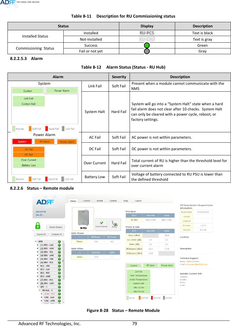
![Advanced RF Technologies, Inc. 80 8.2.2.6.1 Band Display the spectrum that is being used. The band column displays the bandwidth that has been used. The downlink column displays the center frequency of the used downlink band. The uplink column displays the center frequency of the used uplink band. Figure 8-29 PCS Band Information (Status – Remote Module) 8.2.2.6.2 Power & Gain (Admin/User) Display the Downlink output, Downlink/Uplink Attenuation, and Uplink Input/output. Figure 8-30 Power & Gain (Admin) Figure 8-31 Power & Gain (User) Admin o Input [dBm]: Displays the RF input level for Uplink only for the Remote Module. o ALC Atten [dB]: The amount of attenuation used when ALC is activate. o Atten [dB]: The amount of attenuation manually set by the user. o [M]Output [dBm]: Output power of RF transceiver (1st stage amplification). o [H]Output [dBm]: Output power of downlink HPA (2nd stage amplification). User o Input [dBm]: Displays the RF input level for Uplink only for the Remote Module. o Atten [dB]: The amount of attenuation manually set by the user. o Output [dBm]: Displays the total composite output power.](https://usermanual.wiki/ADRF-KOREA/ADX-R-SMR.User-Manual-Installaion-Manual-rev-Part3/User-Guide-2625930-Page-2.png)
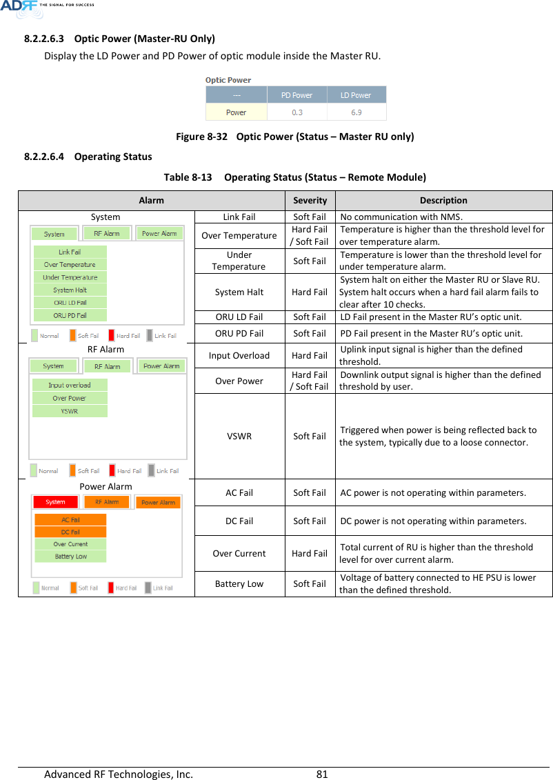
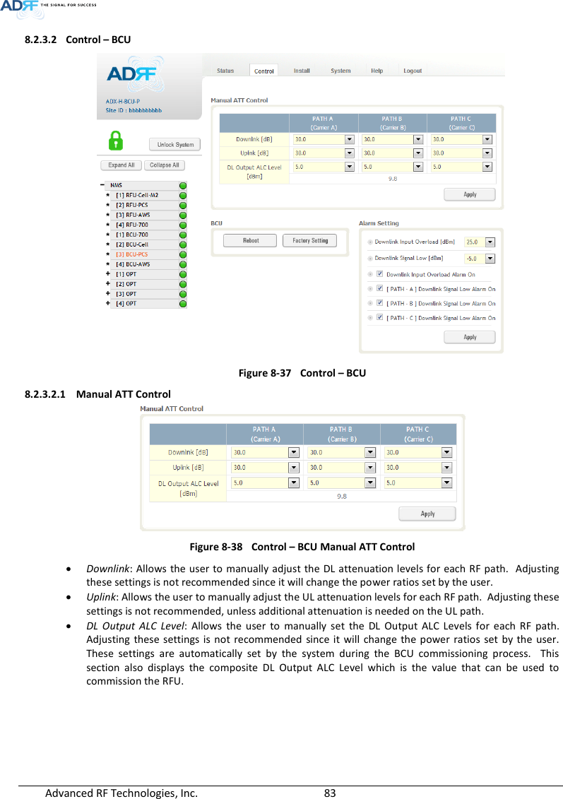
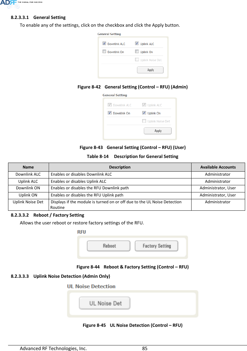
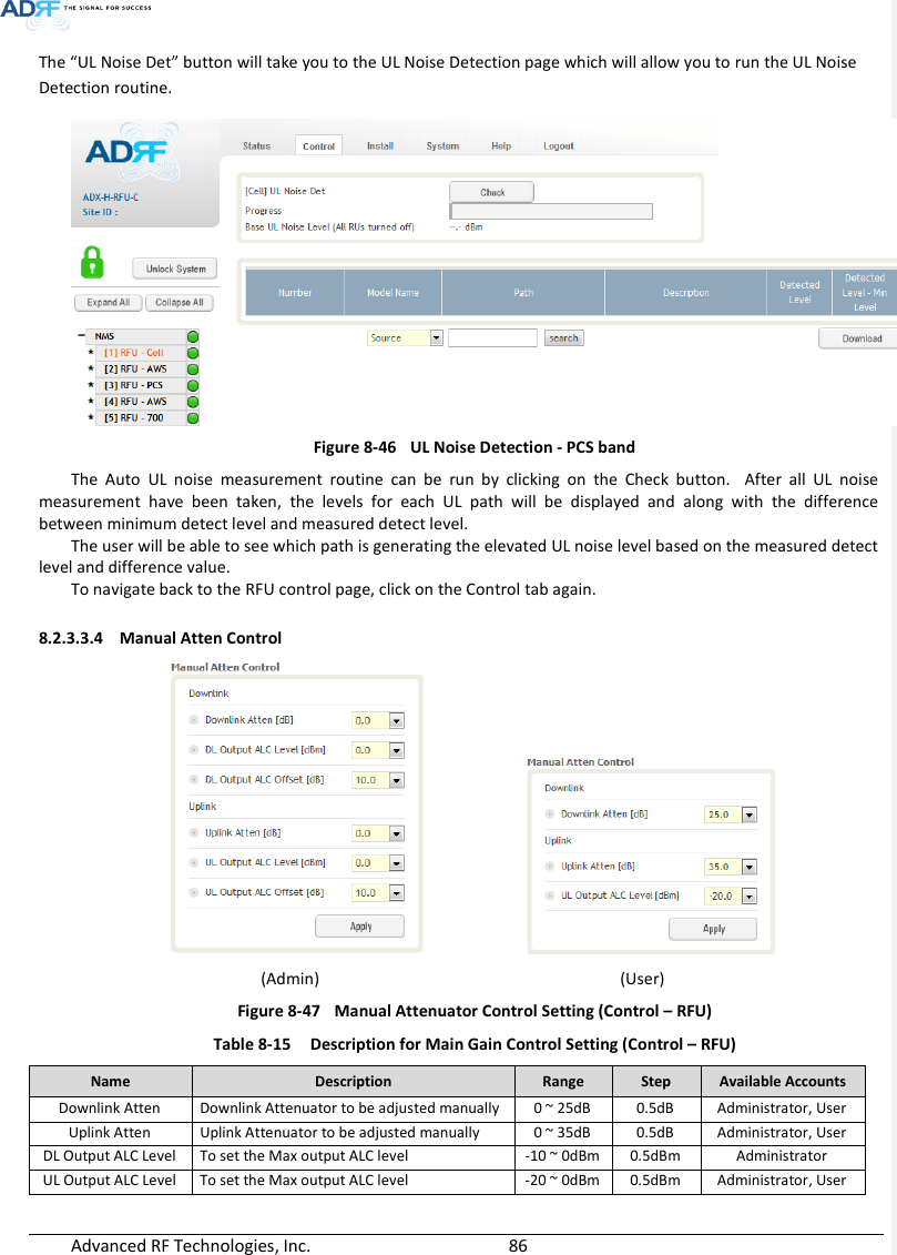
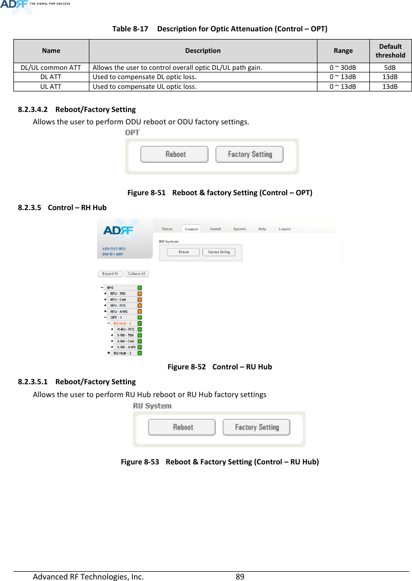
![Advanced RF Technologies, Inc. 84 8.2.3.2.2 Reboot / Factory Setting Allows the user reboot or restore factory settings of the BCU. Figure 8-39 Control – BCU Reboot/Factory Setting 8.2.3.2.3 Alarm Setting Figure 8-40 Control – BCU Alarm Setting Downlink Input Overload: Allows the user to specify the level at which the DL Input Overload alarm is triggered. Values range from 0 dBm to +25 dBm. Downlink Signal Low: Allows the user to specify the level at which the DL Signal Low alarm is triggered. Values range from -10 dBm to +20 dBm. Downlink Input Overload Alarm On: Allows to user to enable or disable the Input Overload Alarm [Path – A/B/C] Downlink Signal Low Alarm On: Allows the user to enable or disable the DL Signal Low alarm for each RF path. 8.2.3.3 Control – RFU Figure 8-41 Control - RFU](https://usermanual.wiki/ADRF-KOREA/ADX-R-SMR.User-Manual-Installaion-Manual-rev-Part3/User-Guide-2625930-Page-6.png)

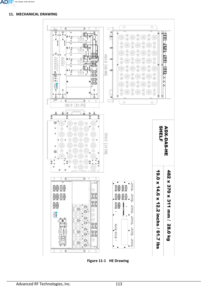
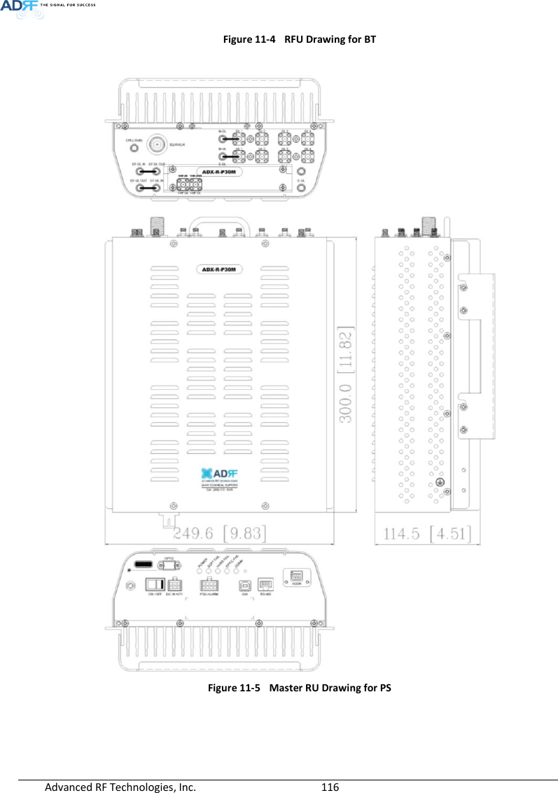
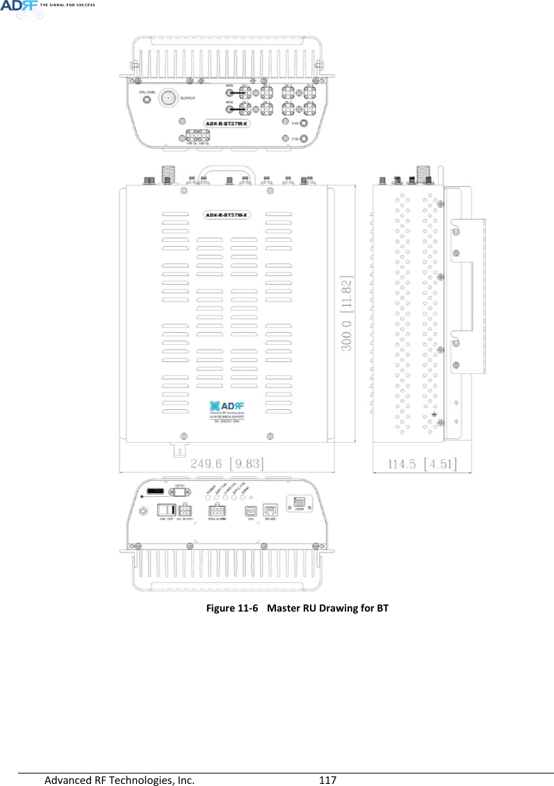
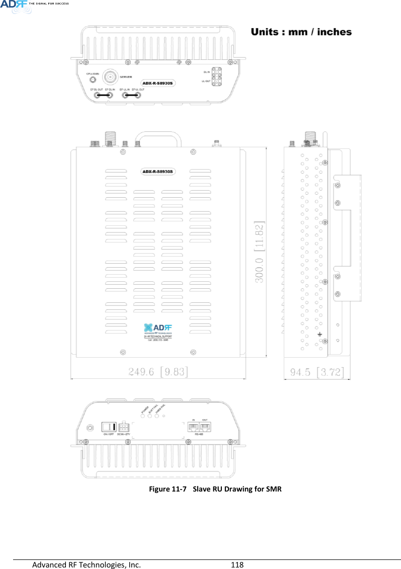
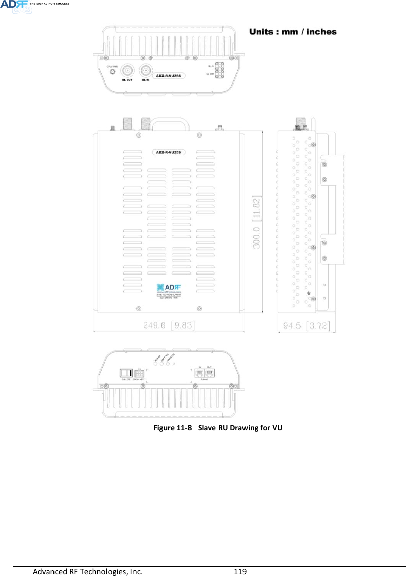
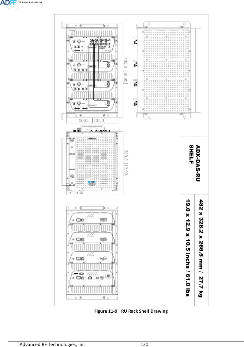
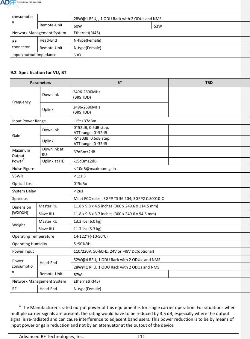
![Advanced RF Technologies, Inc. 110 9. SYSTEM SPECIFICATION 9.1 Specification for PS78, SMR Parameters PS78 SMR Frequency Downlink P7 758-775MHz S8 851-869MHz S9 929-930MHz 935-940MHz Uplink P7 788-805MHz S8 806-824MHz S9 896-901MHz Input Power Range 0~+25dBm Gain Downlink 5~30dB, 0.5dB step, ATT range: 0~25dB Uplink -5~30dB, 0.5dB step, ATT range: 0~35dB Maximum Output Power1 Downlink at RU 30dBm±2dB Uplink at HE -15dBm±2dB Noise Figure < 10dB@maximum gain VSWR < 1:1.5 Optical Loss 0~5dBo System Delay < 2us Spurious Meet FCC rules, 3GPP TS 36.104, 3GPP2 C.S0010-C Nominal Band/BW for Industry Canada Downlink P7 749-781 MHz S8 840-880MHz S9 925-949MHz Uplink P7 782-831 MHz S8 811-834MHz S9 887-911MHz Dimension (WXDXH) Head-End Shelf 19.0 x 14.6 x 12.2 inches (482 x 370 x 311 mm) Remote-Unit Shelf 19.0 x 12.9 x 10.5 inches (482 x 328.2 x 266.5 mm) Master RU 11.8 x 9.8 x 4.5 inches (300 x 249.6 x 114.5 mm) Slave RU 11.8 x 9.8 x 3.7 inches (300 x 249.6 x 94.5 mm) Weight Head-End Shelf 83.7 lbs (38.0 Kg) @4 RFU, CHC-H, PSU and NMS Remote-Unit Shelf 61.0 lbs (27.7 kg) @ 1 master RU, 3 Slave RU Master RU 13.2 lbs (6.0 kg) Slave RU 11.7 lbs (5.3 kg) Operating Temperature 14-122F(-10-50°C) Operating Humidity 5~90%RH Power Input 110/220V, 50-60Hz, 24V or -48V DC(optional) Power Head-End 52W@4 RFU, 1 ODU Rack with 2 ODUs and NMS 1 The Manufacturer's rated output power of this equipment is for single carrier operation. For situations when multiple carrier signals are present, the rating would have to be reduced by 3.5 dB, especially where the output signal is re-radiated and can cause interference to adjacent band users. This power reduction is to be by means of input power or gain reduction and not by an attenuator at the output of the device 메모 [H5]: 주파수 범위 수정 15/05/19 메모 [Y6]: 실제로 측정하셔서 기입요청합니다. 15/02/03](https://usermanual.wiki/ADRF-KOREA/ADX-R-SMR.User-Manual-Installaion-Manual-rev-Part3/User-Guide-2625930-Page-32.png)
![Advanced RF Technologies, Inc. 112 connector Remote-Unit N-type(Female) Input/output Impedance 50 9.3 FCC Certification Item FCC Certification ADX-R-SMR Part 20, Part 90 ADX-R-78P Part 90 ADX-R-BT Part 20 10. ANTENNA SPECIFICATIONS 10.1 Omni Antenna Frequency 698-960MHz 1710-2690MHz Polarization Vertical Gain 2dBi 3dBi VSWR <1.7:1 <1.5:1 Impedance 50 Power Rating 50W Note. Please note that integrators, end-users or installers should not use the antenna with more gain than 3dBi(For Model: ADX-R-BT), 2dBi (For Model: ADX-R-SMR, ADX-R-78P) to meet the RF exposure requirement. Part 90.635 requirement Antennas must be installed in accordance with FCC 90.635. With 2 dBi gain antennas the height of the antenna above average terrain (HAAT) is permitted over 1372m. For different gain antennas refer to the relevant rules. Part 90.219 requirement The radiated power must be limited to 1W. Therefore, this device meet the 90.219 (e)(1) 5W ERP limitation requirement. Prior to equipment use the service must be registered with the FCC. This can be done through the FCC’s website at https://signalboosters.fcc.gov/signal-boosters 메모 [Y7]: FCC part 명기 15/02/03 메모 [Y8]: 안테나 규격 추가 15/02/03](https://usermanual.wiki/ADRF-KOREA/ADX-R-SMR.User-Manual-Installaion-Manual-rev-Part3/User-Guide-2625930-Page-34.png)