ADRF KOREA ADX-R-SMR DAS (Distributed Antenna System) User Manual ADX DAS

ADRF KOREA, Inc. DAS (Distributed Antenna System) ADX DAS

User Manual_Installaion Manual rev Part2
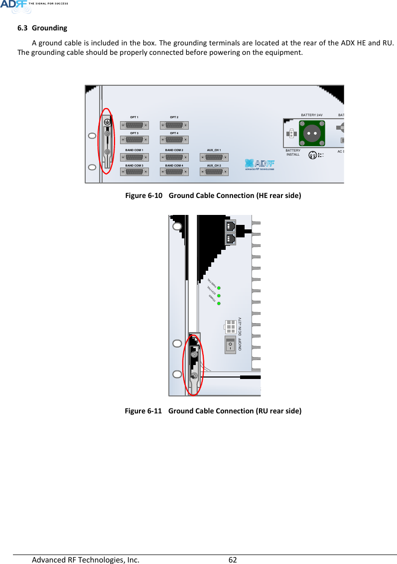
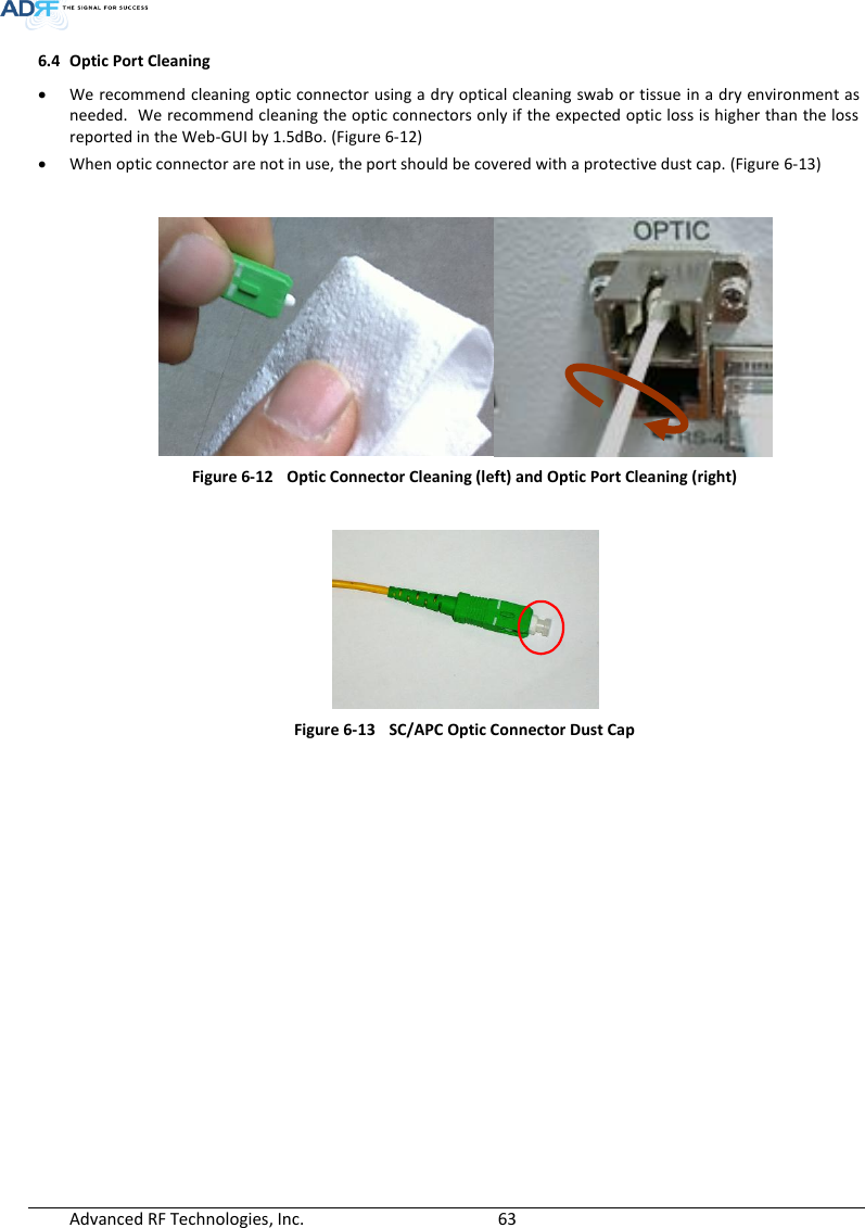
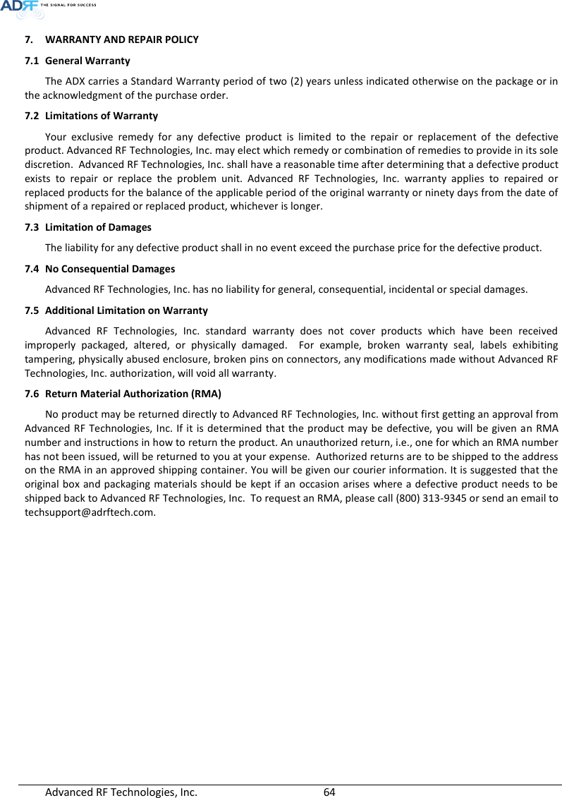
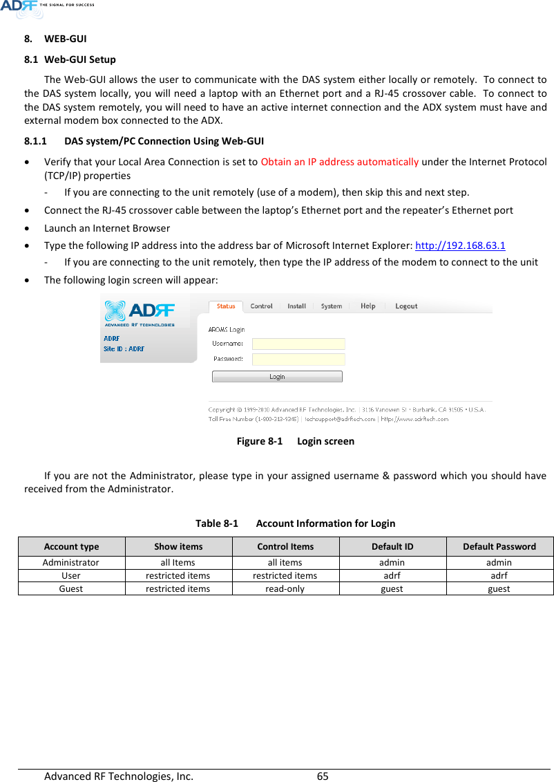
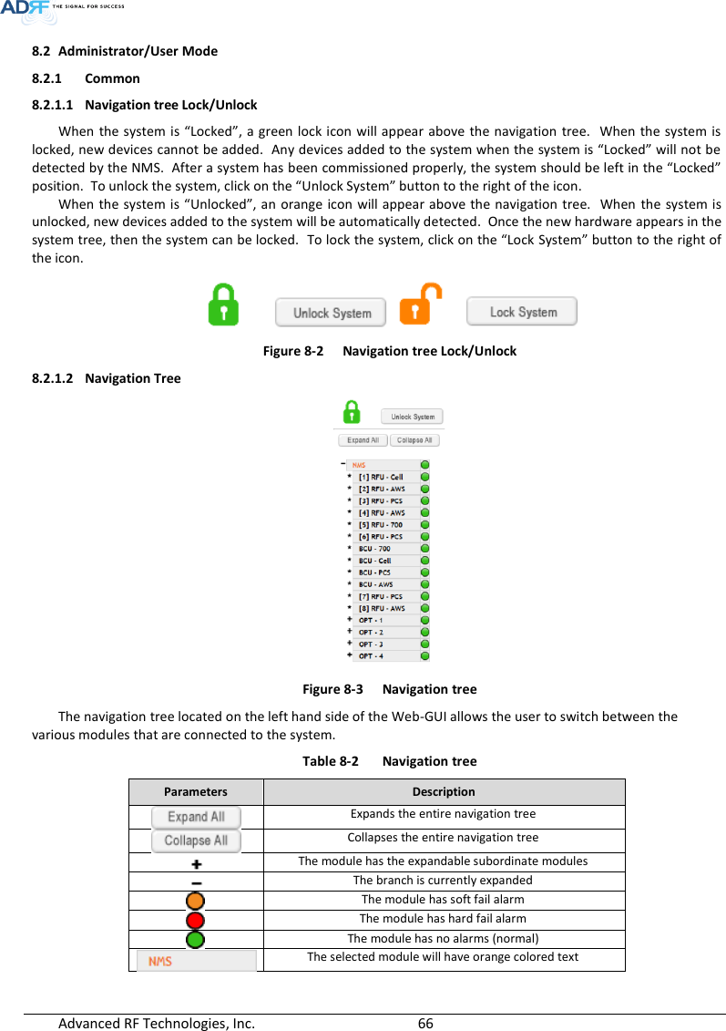
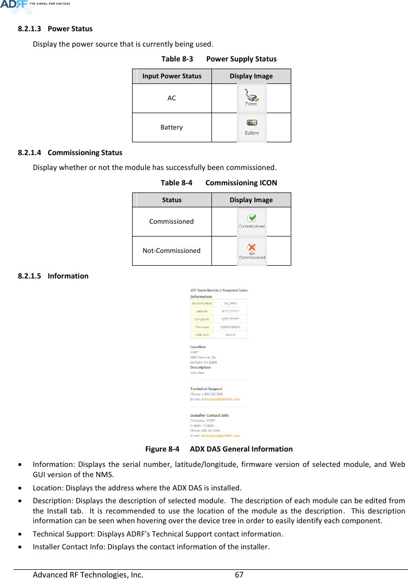
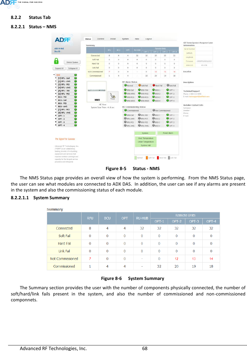
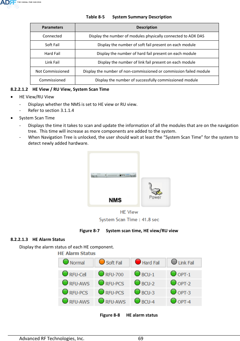
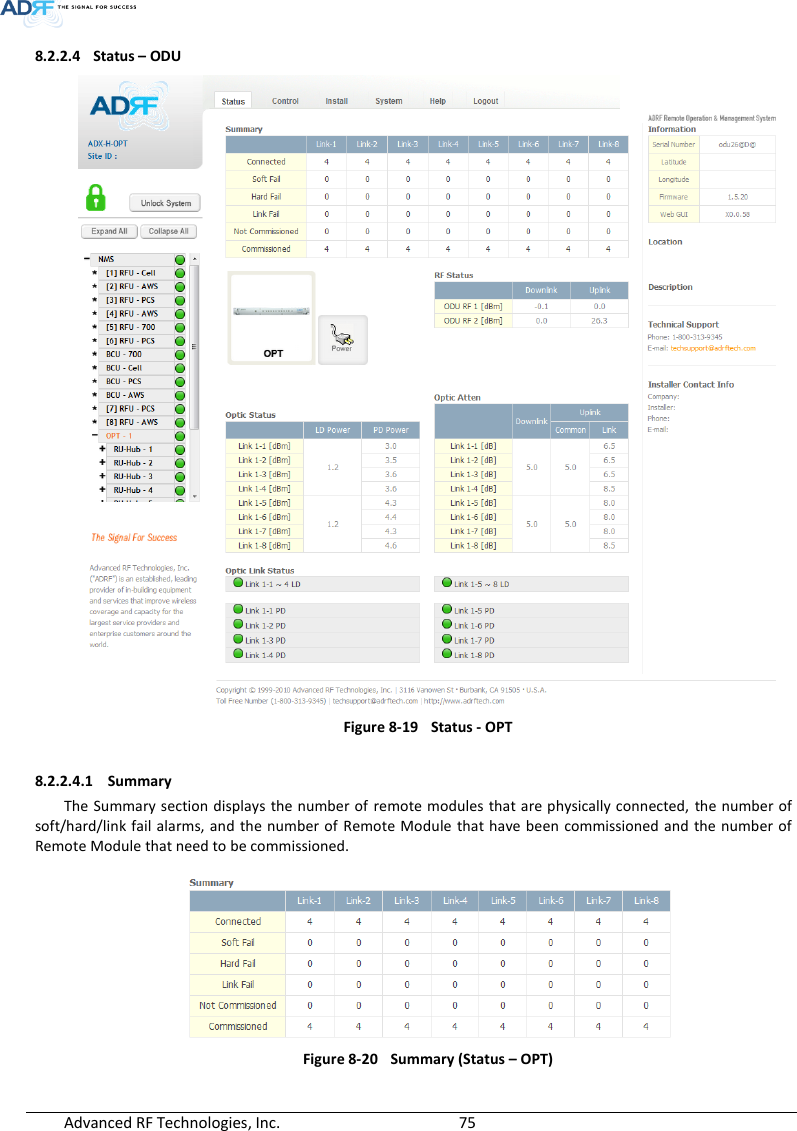
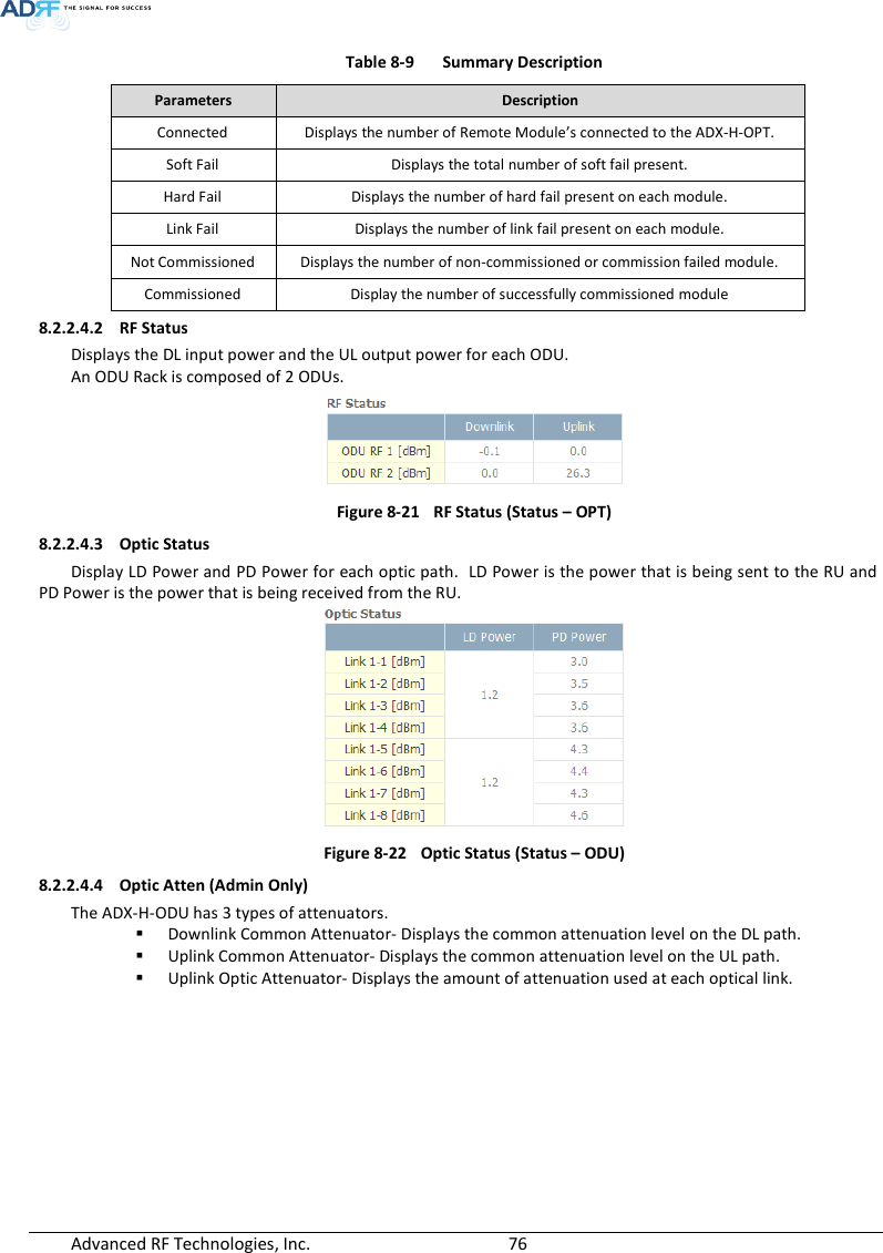
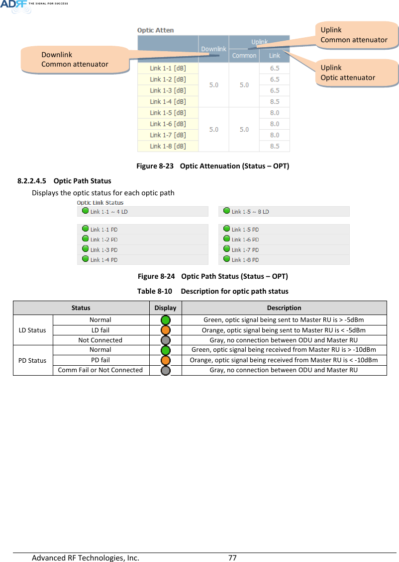
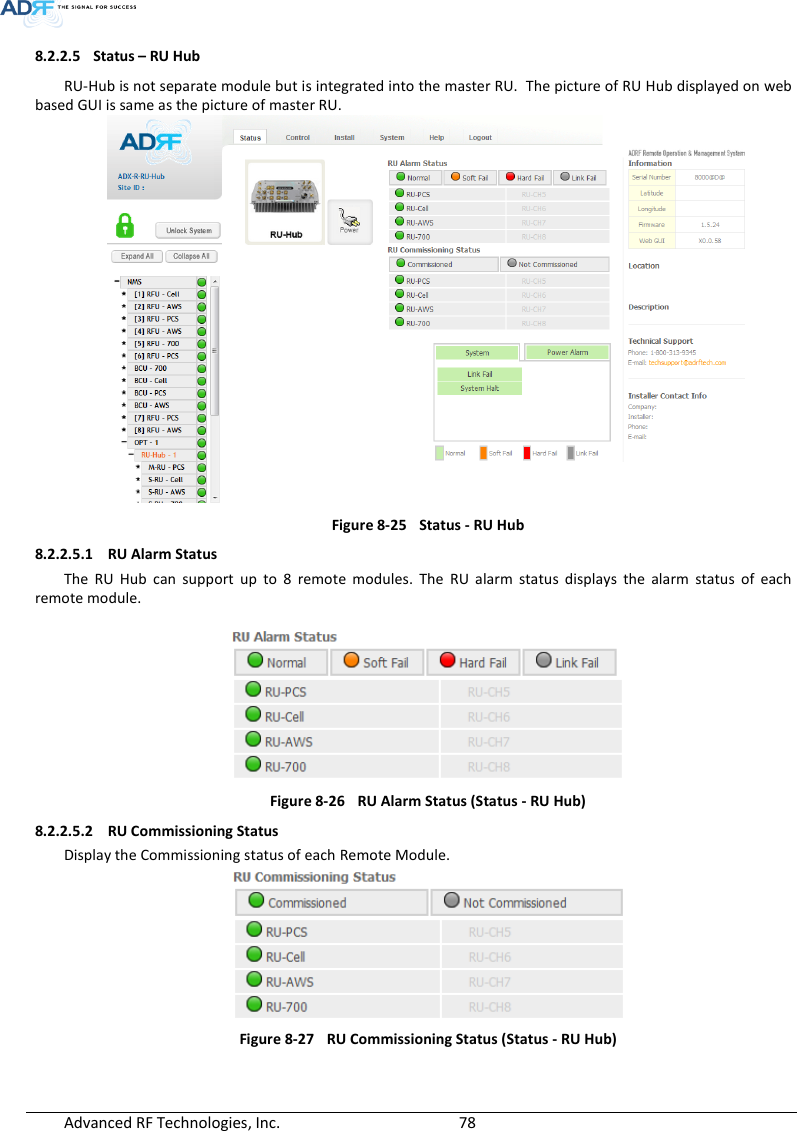
 Advanced RF Technologies, Inc.        46   5. MOUNTING METHOD 5.1 Head End 5.1.1 Rack Mount  Figure 5-1  HE Rack Mount (Front & Rear view)  Expandable up to 4 OPTs, 4 BCUs and 2 AUX CHs   SDADX-H-NMSPOWERSOFT FAIL-HSOFT FAIL-RHARD FAIL-HHARD FAIL-RLINK FAIL-HLINK FAIL-RHOST HE VIEWREMOTE RU VIEWDL OUTUL INHARD FAILDL SIG LOWSOFT FAILPOWERADX-H-RFU-PDL OUTUL INHARD FAILDL SIG LOWSOFT FAILPOWERADX-H-RFU-7DL OUTUL INHARD FAILDL SIG LOWSOFT FAILPOWERADX-H-RFU-CDL OUTUL INHARD FAILDL SIG LOWSOFT FAILPOWERADX-H-RFU-AADX-H-CHCUL1 UL2 UL3 UL4DL1 DL2 DL3 DL4UL5 UL6 UL7 UL8DL5 DL6 DL7 DL8LD FAIL5-8 LINK5 LINK6 LINK7 LINK8LD FAIL1-4 LINK1 LINK2 LINK3 LINK4POWERADX-H-OPTSOFT FAILPOWERADX-H-BCU-PADX-H-PSUPOWERCHG STSLOW BATTAC FAILDC FAILLD FAIL5-8 LINK5 LINK6 LINK7 LINK8LD FAIL1-4 LINK1 LINK2 LINK3 LINK4POWERADX-H-OPTLD FAIL5-8 LINK5 LINK6 LINK7 LINK8LD FAIL1-4 LINK1 LINK2 LINK3 LINK4POWERADX-H-OPTLD FAIL5-8 LINK5 LINK6 LINK7 LINK8LD FAIL1-4 LINK1 LINK2 LINK3 LINK4POWERADX-H-OPTSOFT FAILPOWERADX-H-BCU-PSOFT FAILPOWERADX-H-BCU-PSOFT FAILPOWERADX-H-BCU-PSDDL IN UL OUTDPXADX-H-RFU-PDL IN UL OUTDPXADX-H-RFU-7DL IN UL OUTDPXADX-H-RFU-CDL IN UL OUTDPXADX-H-RFU-AUL5UL6UL7UL8DL5DL6DL7DL8UL1UL2UL3UL4DL1DL2DL3DL4OPT 1 OPT 2OPT 3 OPT 4BAND COM 1 BAND COM 2BAND COM 3 BAND COM 4AUX_CH 1AUX_CH 2OFFVHF UL 2 UL OUT 2 VHF DL 2 DL IN 2LINK 8 LINK 7 LINK 6 LINK 5VHF UL 1 UL OUT 1 VHF DL 1 DL IN 1LINK 4 LINK 3 LINK 2 LINK 1OPTVHF UL 2 UL OUT 2 VHF DL 2 DL IN 2LINK 8 LINK 7 LINK 6 LINK 5VHF UL 1 UL OUT 1 VHF DL 1 DL IN 1LINK 4 LINK 3 LINK 2 LINK 1OPTVHF UL 2 UL OUT 2 VHF DL 2 DL IN 2LINK 8 LINK 7 LINK 6 LINK 5VHF UL 1 UL OUT 1 VHF DL 1 DL IN 1LINK 4 LINK 3 LINK 2 LINK 1OPTVHF UL 2 UL OUT 2 VHF DL 2 DL IN 2LINK 8 LINK 7 LINK 6 LINK 5VHF UL 1 UL OUT 1 VHF DL 1 DL IN 1LINK 4 LINK 3 LINK 2 LINK 1OPTDL IN 3BAND COMCH3 CH2 CH1 SUMDPX 3 UL OUT 3 DL IN 2 DPX 2 UL OUT 2 DL IN 1 DPX 1 UL OUT 1 DL OUT UL INDL IN 3BAND COMCH3 CH2 CH1 SUMDPX 3 UL OUT 3 DL IN 2 DPX 2 UL OUT 2 DL IN 1 DPX 1 UL OUT 1 DL OUT UL INDL IN 3BAND COMCH3 CH2 CH1 SUMDPX 3 UL OUT 3 DL IN 2 DPX 2 UL OUT 2 DL IN 1 DPX 1 UL OUT 1 DL OUT UL INDL IN 3BAND COMCH3 CH2 CH1 SUMDPX 3 UL OUT 3 DL IN 2 DPX 2 UL OUT 2 DL IN 1 DPX 1 UL OUT 1 DL OUT UL INOFFBATTERY INSTALLBATTERYBATTERYAC SELECT OFF/ONAC INS/WOFF ON24V      1A
 Advanced RF Technologies, Inc.        47   5.1.2 Wall Mount  Figure 5-2  HE Wall Mount (Top View)  Expandable up to 3 units (OPT, BCU) or max 3U (132mm) - ODU Rack or BCU will be stacked up above basic 19” HE chassis which includes NMS, RFU, PSU and CHC   ADX-H-NMSPOWERSOFT FAIL-HSOFT FAIL-RHARD FAIL-HHARD FAIL-RLINK FAIL-HLINK FAIL-RHOST HE VIEWREMOTE RU VIEWDL OUTUL INHARD FAILDL SIG LOWSOFT FAILPOWERADX-H-RFU-PDL OUTUL INHARD FAILDL SIG LOWSOFT FAILPOWERADX-H-RFU-7DL OUTUL INHARD FAILDL SIG LOWSOFT FAILPOWERADX-H-RFU-CDL OUTUL INHARD FAILDL SIG LOWSOFT FAILPOWERADX-H-RFU-AADX-H-CHCUL1 UL2 UL3 UL4DL1 DL2 DL3 DL4UL5 UL6 UL7 UL8DL5 DL6 DL7 DL8LD FAIL5-8 LINK5 LINK6 LINK7 LINK8LD FAIL1-4 LINK1 LINK2 LINK3 LINK4POWERADX-H-OPTSOFT FAILPOWERADX-H-BCU-PADX-H-PSUPOWERCHG STSLOW BATTAC FAILDC FAIL
 Advanced RF Technologies, Inc.        48   5.2 Remote Unit 5.2.1 Rack Mount  Figure 5-3  RU Rack Mount (Front view)   SERVERUL1 UL2 UL3 UL4ADX-R-P30MDL1 DL2 DL3 DL4M-DLM-ULCPL(-30dB)E-DLE-ULVHF DL VHF ULEF-DL IN EF-DL OUTEF-UL INEF-UL OUTADX-R-730SDL INSERVERCPL(-30dB)UL OUTEF-DL OUT EF-DL IN EF-UL IN EF-UL OUTDL4 DL3 DL2 DL1 ADX-R-4WS UL4 UL3 UL2 UL1M-ULM-DLADX-R-730SDL INSERVERCPL(-30dB)UL OUTEF-DL OUT EF-DL IN EF-UL IN EF-UL OUTADX-R-PSU-30POWERCHG-STSLOW BATTAC FAILDC FAILADX-R-730SDL INSERVERCPL(-30dB)UL OUTEF-DL OUT EF-DL IN EF-UL IN EF-UL OUTADX-R-C30SDL INSERVERCPL(-30dB)UL OUTEF-DL OUT EF-DL IN EF-UL IN EF-UL OUTADX-R-A30SDL INSERVERCPL(-30dB)UL OUTEF-DL OUT EF-DL IN EF-UL IN EF-UL OUTWiMAXCellularSMR800AWS700MPCSCOM WIFISMR900ADX-R-CHCPOWER SOFT FAIL HARD FAILDL-IN UL-OUT MONSERVERADX-R-V30SSD
 Advanced RF Technologies, Inc.        49   5.2.2 Wall Mount 5.2.2.1 Remote Unit using RU Chassis (ADX-R-CHA-30) Wall mount brackets attached to the individual  remote modules must be removed before sliding the remote modules into the RU Chassis.    Figure 5-4  19” Shelf type - RU Wall Mount (Top view)  5.2.2.2 Individual Remote Module Remote modules can be mounted using the attached mounting bracket that ships with the unit.  Figure 5-5  Remote Module Wall Mount (Top view)   SERVERUL1 UL2 UL3 UL4ADX-R-P30MDL1 DL2 DL3 DL4M-DLM-ULCPL(-30dB)E-DLE-ULVHF DL VHF ULEF-DL IN EF-DL OUTEF-UL INEF-UL OUTADX-R-PSU-30POWERCHG-STSLOW BATTAC FAILDC FAILADX-R-730SDL INSERVERCPL(-30dB)UL OUTEF-DL OUT EF-DL IN EF-UL IN EF-UL OUTADX-R-C30SDL INSERVERCPL(-30dB)UL OUTEF-DL OUT EF-DL IN EF-UL IN EF-UL OUTADX-R-A30SDL INSERVERCPL(-30dB)UL OUTEF-DL OUT EF-DL IN EF-UL IN EF-UL OUTWiMAXCellularSMR800AWS700MPCSCOM WIFISMR900ADX-R-CHCPOWER SOFT FAIL HARD FAILDL-IN UL-OUT MONSERVERADX-R-V30SADX-R-730SDL INSERVERCPL(-30dB)UL OUTEF-DL OUT EF-DL IN EF-UL IN EF-UL OUTDL4 DL3 DL2 DL1 ADX-R-4WS UL4 UL3 UL2 UL1M-ULM-DLADX-R-730SDL INSERVERCPL(-30dB)UL OUTEF-DL OUT EF-DL IN EF-UL IN EF-UL OUT
 Advanced RF Technologies, Inc.        50   6. INSTALLATION 6.1 Pre-Installation Inspection Please follow these procedures before installing ADX equipment: o Verify the number of packages received against the packing list. o Check  all packages for  external damage;  report any external damage  to  the  shipping carrier. If there is damage, a shipping agent should be present before you unpack and inspect the contents because damage caused during transit is the responsibility of the shipping agent. o Open  and  check  each  package  against  the  packing  list.  If  any  items  are  missing,  contact  ADRF customer service. o If damage is discovered at the time of installation, contact the shipping agent. o Verify the AC voltage with DVM (Volt meter), then select the either 110V or 220V AC using the selection  switch  located  at  the  rear  of  HE  and  RU  PSU.    The  ADX  ships  with  the  AC  selection switch set to the 110V position.  Incorrect AC selection can damage the ADX equipment. 6.2 ADX DAS Installation Procedure 6.2.1 HE Installation Procedure  CAUTION: ADX DAS HE should be installed inside building only.    6.2.1.1 Installing a ADX DAS HE in a rack The ADX HE chassis mounts in a standard 19” (483mm) equipment rack. Allow clearance of 3” (76mm) at the front and rear, and 2” (51mm) on both sides for air circulation. No top or bottom clearance is required.   Consideration: - Eight mounting holes are located on 4 corners of ADX HE to attach it to the 19” rack. The ADX HE must be securely attached to a rack that can support the weight of the ADX.  Mount procedure - The following steps should be followed while mounting the ADX HE  Detach the wall mount bracket assembled located at the base of the ADX-HE chassis  Verify that the HE and Mounting holes are in good condition  Set the ADX DAS HE against the 19”rack and secure the unit with screws  Verify that ADX HE is securely attached  Connect the GND cable  Connect the RF cable  Connect the Power  Connect the Optic cable
 Advanced RF Technologies, Inc.        51    Figure 6-1  ADX HE 19” Rack Mount Instructions
 Advanced RF Technologies, Inc.        52   6.2.1.2 Wall mounting the ADX DAS HE If  the ADX HE  chassis  is being  mounted  to a  wall,  then allow clearance  of at least  17”  (430mm)  on  the  top (front side of HE) and 2” (51mm) on the bottom  (rear side of HE) and 2” (51mm) on both sides and front for air circulation.   Mount procedure - The following steps should be followed when wall mounting the ADX HE  Verify that the HE and Mounting hole are in good condition  Place the ADX HE against the wall and mark of the mounting holes  Drill holes(4holes, 18Φmm, 50mm depth) in the installation surface and insert the anchor bolts  Bolt the ADX HE to the wall  Make sure the ADX HE is securely attached  Connect the GND cable  Connect the RF cable  Connect the Power  Connect the Optic cable  Figure 6-2  ADX HE Wall Mount Instructions
 Advanced RF Technologies, Inc.        53    6.2.1.2.1 Installing added rack type modules into basic HE chassis Additional modules such as the ADX-H-RACK-ODU and ADX-H-BCU can be mounted to the Chassis (ADX-H-CHA) using the included mounting brackets that come with the add-on modules.  A maximum of up to 3 addon modules (OPT, BCU) can be mounted to the chassis - ODU Rack or BCU will be stacked up above basic 19” HE chassis which includes NMS, RFU, PSU and CHC  Figure 6-3  Wall Mount Instructions for ADX-HE added 1U Unit
 Advanced RF Technologies, Inc.        54   6.2.2 RU Installation Procedure  CAUTION: ADX DAS RU should be installed inside building only.    6.2.2.1 Installing a ADX DAS RU in a rack  If the ADX RU chassis is being wall mounted then allow clearance of 3” (76mm) front and rear, and 2” (51mm) on both sides for air circulation. No top or bottom clearance is required. When  ADX  DAS  RU  mounts  in  a  standard  19”  equipment  rack,  rack  or  wall  type  fan  is  needed  for  heat dissipation. The rack type fan (ADX-R-FAN) must have at least 1.75" of clearance.   Consideration: - Eight mounting holes are located on 4 corners of ADX RU to attach it to the 19” rack. The ADX RU must be securely attached to support the weight of the ADX-RU units.  Mount procedure - The following steps should be followed while mounting the ADX-RU units  Detach the wall mount bracket located at the base of the ADX-RU chassis  Verify that the RU and Mounting hole are in good condition  Screw the ADX DAS RU to the 19”rack  Make sure the ADX RU is securely attached  Connect the GND cable  Connect the RF cable  Connect the Power  Connect the Optic cable
 Advanced RF Technologies, Inc.        55    Figure 6-4  ADX-RU 19” Rack Mount Instructions
 Advanced RF Technologies, Inc.        56   6.2.2.2 Wall mounting the ADX DAS RU If the  ADX RU chassis  is being  mounted to a  wall, then  allow clearance of  at  least 16”  (406mm) on  the  top (front  side  of  RU),  2”  (51mm)  on  the  bottom  (rear  side  of  RU)  and  2”  (51mm)  on  both sides  and  front  for  air circulation.   Mount procedure - The following steps should be followed while mounting the ADX RU   Verify that the RU and Mounting hole are in good condition  Place the RU chassis up against the wall and mark off the mounting holes  Drill holes(4holes, 18Φmm, 50mm depth) in the installation surface and insert the anchor bolts  Bolt the RU chassis to the wall  Install the individual Sub-RU inside of the chassis  Make sure the RU chassis is securely attached  Connect the RF cable  Connect the Antenna cable  Connect the Power  Connect the Optic cable  Figure 6-5  ADX-RU Wall Mount Instructions
 Advanced RF Technologies, Inc.        57   6.2.2.2.1 Installing added rack type modules into basic HE chassis Additional  modules  such  as  the  ADX-R-CHC  (channel  combiner)  and  ADX-R-PSU  (power  supply  unit)  can  be mounted to the Chassis (ADX-R-CHA) using the included mounting brackets that come with the add-on modules.  A maximum of up to 2 addon modules (ADX-R-CHC and ADX-R-PSU) can be mounted to the chassis. - ADX-R-PSU or ADX-R-CHC will be stacked up above basic 19” RU chassis which holds the Master/Slave RU units.  Figure 6-6  Wall Mount Instructions for ADX-RU added 1.5U Unit
 Advanced RF Technologies, Inc.        58   6.2.2.3 Wall mounting an ADX Remote Module   Mount procedure - The following steps should be followed while mounting the Remote Module   Verify that the RU and Mounting hole are in good condition  Separate the wall mount bracket from the Sub-RU  Placed the wall mount bracket against the wall and mark off the mounting holes  Drill holes(4holes, 6Φmm) in the installation surface then insert the enclosed anchor bolts  Bolt the mounting bracket to the wall  Install the Sub-RU to the mounting bracket  Fasten the Sub-RU to the mounting bracket using the included screws  Verify that the Remote Module is securely attached  Connect the Antenna cable  Connect the Power  Connect the Optic cable (if applicable)  Figure 6-7  Remote Module Wall Mount Instructions
 Advanced RF Technologies, Inc.        59   6.2.3 ADX-H-OEU Installation Procedure  CAUTION: ADX-H-OEU should be installed inside building only.    6.2.3.1 Installing a ADX-H-OEU in a Rack  The ADX-H-OEU mounts in a standard 19” (483mm) equipment rack. Allow clearance of 3” (76mm) front and rear, and 2” (51mm) on both sides for air circulation. No top or bottom clearance is required.   Consideration: - Four mounting holes are located on 4 corners of ADX-H-OEU to attach it to the 19” rack. The ADX-H-OEU must be securely attached to support the weight of the unit.  Mount procedure - The following steps should be followed while mounting the ADX-H-OEU  Detach the wall mount brackets located at the base of the ADX-H-OEU  Verify that the OEU and mounting hole are in good condition  Screw the ADX-H-OEU to the 19”rack  Make sure the ADX-H-OEU is securely attached  Connect the GND cable  Connect the RF cable  Connect the Power  Connect the Optic cable
 Advanced RF Technologies, Inc.        60    Figure 6-8  ADX-H-OEU Rack Mount Instructions
 Advanced RF Technologies, Inc.        61   6.2.3.2 Wall mounting the ADX-H-OEU  Mount procedure - The following steps should be followed while mounting the ADX-H-OEU    Verify that the OEU and Mounting hole are in good condition  Drill holes(4holes, 6Φmm) in the installation surface then insert the enclosed anchor bolts  Set the ADX-H-OEU against the wall  Make sure the OEU is securely attached  Connect the RF cable  Connect the Antenna cable  Connect the Power  Connect the Optic cable   Figure 6-9  ADX-H-OEU Wall Mount Instructions
 Advanced RF Technologies, Inc.        62   6.3 Grounding A ground cable is included in the box. The grounding terminals are located at the rear of the ADX HE and RU.  The grounding cable should be properly connected before powering on the equipment.    Figure 6-10  Ground Cable Connection (HE rear side)   Figure 6-11  Ground Cable Connection (RU rear side)      OPT 1 OPT 2OPT 3 OPT 4BAND COM 1 BAND COM 2BAND COM 3 BAND COM 4AUX_CH 1AUX_CH 2BATTERY INSTALLBATTERY 24V BATT S/WAC SELECT ON/OFF AC INOFFDC IN +27VON/OFFOUTPOWERSOFT FAILHARD FAILIN
 Advanced RF Technologies, Inc.        63   6.4 Optic Port Cleaning  We recommend cleaning optic connector using a dry optical cleaning swab or tissue in a dry environment as needed.  We recommend cleaning the optic connectors only if the expected optic loss is higher than the loss reported in the Web-GUI by 1.5dBo. (Figure 6-12)  When optic connector are not in use, the port should be covered with a protective dust cap. (Figure 6-13)   Figure 6-12  Optic Connector Cleaning (left) and Optic Port Cleaning (right)   Figure 6-13  SC/APC Optic Connector Dust Cap
 Advanced RF Technologies, Inc.        64   7. WARRANTY AND REPAIR POLICY  7.1 General Warranty The ADX carries a Standard Warranty period of two (2) years unless indicated otherwise on the package or in the acknowledgment of the purchase order. 7.2 Limitations of Warranty Your  exclusive  remedy  for  any  defective  product  is  limited  to  the  repair  or  replacement  of  the  defective product. Advanced RF Technologies, Inc. may elect which remedy or combination of remedies to provide in its sole discretion.  Advanced RF Technologies, Inc. shall have a reasonable time after determining that a defective product exists  to  repair  or  replace  the  problem  unit.  Advanced  RF  Technologies,  Inc.  warranty  applies  to  repaired  or replaced products for the balance of the applicable period of the original warranty or ninety days from the date of shipment of a repaired or replaced product, whichever is longer. 7.3 Limitation of Damages The liability for any defective product shall in no event exceed the purchase price for the defective product.  7.4 No Consequential Damages Advanced RF Technologies, Inc. has no liability for general, consequential, incidental or special damages.  7.5 Additional Limitation on Warranty Advanced  RF  Technologies,  Inc.  standard  warranty  does  not  cover  products  which  have  been  received improperly  packaged,  altered,  or  physically  damaged.    For  example,  broken  warranty  seal,  labels  exhibiting tampering, physically abused enclosure, broken pins on connectors, any modifications made without Advanced RF Technologies, Inc. authorization, will void all warranty.  7.6 Return Material Authorization (RMA) No product may be returned directly to Advanced RF Technologies, Inc. without first getting an approval from Advanced RF  Technologies, Inc. If it is determined that  the product may  be defective,  you will be given an  RMA number and instructions in how to return the product. An unauthorized return, i.e., one for which an RMA number has not been issued, will be returned to you at your expense.  Authorized returns are to be shipped to the address on the RMA in an approved shipping container. You will be given our courier information. It is suggested that the original box and packaging materials  should be kept if an occasion arises where a defective product needs to be shipped back to Advanced RF Technologies, Inc.  To request an RMA, please call (800) 313-9345 or send an email to techsupport@adrftech.com.
 Advanced RF Technologies, Inc.        65   8. WEB-GUI 8.1 Web-GUI Setup The Web-GUI allows the user to communicate with the DAS system either locally or remotely.  To connect to the DAS system locally, you will need a laptop with an Ethernet port and a RJ-45 crossover cable.  To connect to the DAS system remotely, you will need to have an active internet connection and the ADX system must have and external modem box connected to the ADX. 8.1.1 DAS system/PC Connection Using Web-GUI  Verify that your Local Area Connection is set to Obtain an IP address automatically under the Internet Protocol (TCP/IP) properties - If you are connecting to the unit remotely (use of a modem), then skip this and next step.   Connect the RJ-45 crossover cable between the laptop’s Ethernet port and the repeater’s Ethernet port  Launch an Internet Browser  Type the following IP address into the address bar of Microsoft Internet Explorer: http://192.168.63.1 - If you are connecting to the unit remotely, then type the IP address of the modem to connect to the unit  The following login screen will appear:  Figure 8-1  Login screen  If you are not the Administrator, please type in your assigned username & password which you should have received from the Administrator.   Table 8-1  Account Information for Login Account type Show items Control Items Default ID Default Password Administrator all Items all items admin admin User restricted items restricted items adrf adrf Guest restricted items read-only guest guest
 Advanced RF Technologies, Inc.        66   8.2 Administrator/User Mode 8.2.1 Common 8.2.1.1 Navigation tree Lock/Unlock When the system  is “Locked”,  a green  lock icon will appear  above the navigation tree.    When  the system is locked, new devices cannot be added.  Any devices added to the system when the system is “Locked” will not be detected by the NMS.  After a system has been commissioned properly, the system should be left in the “Locked” position.  To unlock the system, click on the “Unlock System” button to the right of the icon. When the system is “Unlocked”, an orange icon will appear above the navigation tree.   When the system is unlocked, new devices added to the system will be automatically detected.  Once the new hardware appears in the system tree, then the system can be locked.   To lock the system, click on the “Lock System” button to the right of the icon.  Figure 8-2  Navigation tree Lock/Unlock 8.2.1.2 Navigation Tree    Figure 8-3  Navigation tree The navigation tree located on the left hand side of the Web-GUI allows the user to switch between the various modules that are connected to the system.  Table 8-2  Navigation tree Parameters Description  Expands the entire navigation tree  Collapses the entire navigation tree  The module has the expandable subordinate modules  The branch is currently expanded  The module has soft fail alarm  The module has hard fail alarm  The module has no alarms (normal)  The selected module will have orange colored text
 Advanced RF Technologies, Inc.        67   8.2.1.3 Power Status  Display the power source that is currently being used. Table 8-3  Power Supply Status Input Power Status Display Image AC  Battery  8.2.1.4 Commissioning Status Display whether or not the module has successfully been commissioned. Table 8-4  Commissioning ICON Status Display Image Commissioned  Not-Commissioned  8.2.1.5 Information   Figure 8-4  ADX DAS General Information  Information:  Displays  the  serial number,  latitude/longitude,  firmware  version  of  selected  module,  and  Web GUI version of the NMS.  Location: Displays the address where the ADX DAS is installed.  Description: Displays the description of selected module.  The description of each module can be edited from the  Install  tab.    It  is  recommended  to  use  the  location  of  the  module  as  the  description.    This  description information can be seen when hovering over the device tree in order to easily identify each component.  Technical Support: Displays ADRF’s Technical Support contact information.  Installer Contact Info: Displays the contact information of the installer.
 Advanced RF Technologies, Inc.        68   8.2.2 Status Tab 8.2.2.1 Status – NMS  Figure 8-5  Status - NMS The NMS Status page provides an overall view of how the system is performing.  From the NMS Status page, the user can see what modules are connected to ADX DAS.  In addition, the user can see if any alarms are present in the system and also the commissioning status of each module.  8.2.2.1.1 System Summary  Figure 8-6  System Summary The Summary section provides the user with the number of components physically connected, the number of soft/hard/link  fails  present  in  the  system,  and  also  the  number  of  commissioned  and  non-commissioned componnets.
 Advanced RF Technologies, Inc.        69   Table 8-5  System Summary Description Parameters Description Connected Display the number of modules physically connected to ADX DAS Soft Fail Display the number of soft fail present on each module Hard Fail Display the number of hard fail present on each module Link Fail Display the number of link fail present on each module Not Commissioned Display the number of non-commissioned or commission failed module Commissioned Display the number of successfully commissioned module 8.2.2.1.2 HE View / RU View, System Scan Time  HE View/RU View - Displays whether the NMS is set to HE view or RU view. - Refer to section 3.1.1.4  System Scan Time - Displays the time it takes to scan and update the information of all the modules that are on the navigation tree.  This time will increase as more components are added to the system. - When Navigation Tree is unlocked, the user should wait at least the “System Scan Time” for the system to detect newly added hardware.  Figure 8-7  System scan time, HE view/RU view 8.2.2.1.3 HE Alarm Status  Display the alarm status of each HE component.   Figure 8-8  HE alarm status
 Advanced RF Technologies, Inc.        70   8.2.2.1.4 HE Commissioning Status Display commissioning status of each HE component.  Figure 8-9  HE Commissioning status Table 8-6  Description for HE Commissioning status Status Display Description Installed Status Physically Installed  Text is black Physically Not-Installed  Text is gray Commissioning  Status Success  Green Failed or not commissioned  Gray 8.2.2.1.5 Alarm Displays alarm status of the NMS. If an alarm is present in the system, the color of the system alarm tab will change according to the type of failure. Table 8-7  Description for NMS alarm Alarm Severity Description System  Over Temperature Hard Fail / Soft Fail Temperature of NMS is higher than the threshold level for over temperature alarm Under Temperature Soft Fail Temperature of the NMS is lower than the threshold level for under temperature alarm System Halt Hard Fail HE system halt Power Alarm  AC Fail Soft Fail AC power is operating outside of its normal range DC Fail Soft Fail DC power is operating outside of its normal range Over Current Hard Fail Total current of HE is higher than the threshold level for over current alarm Battery Low Soft Fail Voltage of battery connected to HE PSU is lower than the defined threshold
 Advanced RF Technologies, Inc.        71   8.2.2.2 Status – BCU  Figure 8-10  Status – BCU  8.2.2.2.1 Band Displays the bandwidth and the frequency ranges for DL and UL of the BCU module.  Figure 8-11  Status – BCU Band 8.2.2.2.2 Power & Atten  Figure 8-12  Status – BCU Power & Atten
 Advanced RF Technologies, Inc.        72    DL Commissioning Level: Displays the commissioning level for each individual RF path.  If unit has not been commissioned, “Not Commissioned” will be displayed.  DL Input: Displays the currently incoming signal strength of each RF path along with the composite DL input power of all 3 RF paths.  Atten:  Displays  the  attenuation  values  that  the  system  is  currently  using  which  is  defined  by  the power ratios specified by the user.  DL Output: Displays the output value for each RF path along with the composite DL output power of all 3 RF paths.  The DL Output level for each RF path will not exceed 5dBm and the composite output power will not exceed 10 dBm.  8.2.2.2.3 Power Ratio  Figure 8-13  Status – BCU Power Ratio  Targeted DL Output Power: Displays desired power ratios specified by the user.  If unit has not been commissioned, “Not Commissioned” will be displayed.  Actual DL Output Power: Displays the currently power  ratios that the system is using.  These values will fluctuate based on the amount of traffic that is in the system. 8.2.2.2.4 Alarm Displays the current alarm status of each individual RF path.  Parameters for both DL Signal Low and DL Input Overload can be specified from the Control tab.  Figure 8-14  Status – BCU Alarm
 Advanced RF Technologies, Inc.        73   8.2.2.3 Status – RFU  Figure 8-15  Status – RFU 8.2.2.3.1 Band Displays the bandwidth and the frequency ranges for DL and UL of the RFU module.   Figure 8-16  Status – RFU Band 8.2.2.3.2 Power & Gain (Admin/User)  Admin  Mode-  Displays  the  Downlink  Input/output,  Downlink/Uplink  Attenuation,  and  Uplink Output.  User Mode- Displays the Downlink Input, Downlink/Uplink Attenuation, and Uplink Output.  Figure 8-17  Power & Gain Display (Admin)
 Advanced RF Technologies, Inc.        74    Figure 8-18  Power & Gain Display (User)  Input [dBm]: Displays the Downlink RF input level which comes from the ADX-H-BCU, BTS.  This value should be between 0 to 25 dBm.  ALC Atten [dB]: The amount of attenuation that is being used by the system when ALC is active.  Atten [dB]: The amount of attenuation that has been set manually by the user.  Output [dBm]: The downlink/uplink output power of the RFU and NOT the output power of the RU. 8.2.2.3.3 Alarm Displays  System, RF, and  Power Alarms.   If an  alarm is  present  in  the system,  then  the  color of  the  tab will change according to the type of failure.     Table 8-8  RFU Alarm Status Alarm Severity Description System  Link Fail Soft Fail A component is physically connected, but the NMS is unable to communicate with it. Over Temperature Hard Fail / Soft Fail The temperature of NMS is higher than the threshold level for over temperature alarm. Under Temperature Soft Fail The temperature of NMS is lower than the threshold level for under temperature alarm. System Halt Hard Fail System will go into a “System Halt” state when a hard fail alarm does not clear after 10 checks.  System Halt can only be cleared with a power cycle, reboot, or factory settings. RF Alarm  DL Signal not detected Soft Fail Downlink input signal is lower than the defined threshold by user. DL Signal Low Soft Fail Downlink input signal is lower than the defined threshold by user. Input Overload Hard Fail / Soft Fail Downlink input signal is higher than the defined threshold. Overpower Hard Fail / Soft Fail Uplink output signal is higher than the defined threshold by user. Power Alarm  AC Fail Soft Fail AC power is not operating within parameters. DC Fail Soft Fail DC power is not operating within parameters. Over Current Hard Fail Total current of HE is higher than the threshold level for over current alarm. Battery Low Soft Fail Voltage of battery connected to HE PSU is lower than the defined threshold.
 Advanced RF Technologies, Inc.        75   8.2.2.4 Status – ODU   Figure 8-19  Status - OPT  8.2.2.4.1 Summary  The Summary section displays the number of  remote modules that are physically connected,  the number of soft/hard/link  fail alarms, and the number of  Remote Module that have been commissioned and  the  number of Remote Module that need to be commissioned.     Figure 8-20  Summary (Status – OPT)
 Advanced RF Technologies, Inc.        76   Table 8-9  Summary Description Parameters Description Connected Displays the number of Remote Module’s connected to the ADX-H-OPT. Soft Fail Displays the total number of soft fail present. Hard Fail Displays the number of hard fail present on each module. Link Fail Displays the number of link fail present on each module. Not Commissioned Displays the number of non-commissioned or commission failed module. Commissioned Display the number of successfully commissioned module 8.2.2.4.2 RF Status  Displays the DL input power and the UL output power for each ODU. An ODU Rack is composed of 2 ODUs.  Figure 8-21  RF Status (Status – OPT) 8.2.2.4.3 Optic Status  Display LD Power and PD Power for each optic path.  LD Power is the power that is being sent to the RU and PD Power is the power that is being received from the RU.  Figure 8-22  Optic Status (Status – ODU) 8.2.2.4.4 Optic Atten (Admin Only) The ADX-H-ODU has 3 types of attenuators.  Downlink Common Attenuator- Displays the common attenuation level on the DL path.  Uplink Common Attenuator- Displays the common attenuation level on the UL path.  Uplink Optic Attenuator- Displays the amount of attenuation used at each optical link.
 Advanced RF Technologies, Inc.        77    Figure 8-23  Optic Attenuation (Status – OPT) 8.2.2.4.5 Optic Path Status Displays the optic status for each optic path  Figure 8-24  Optic Path Status (Status – OPT) Table 8-10  Description for optic path status Status Display Description LD Status Normal  Green, optic signal being sent to Master RU is > -5dBm LD fail  Orange, optic signal being sent to Master RU is < -5dBm Not Connected  Gray, no connection between ODU and Master RU PD Status Normal  Green, optic signal being received from Master RU is > -10dBm PD fail  Orange, optic signal being received from Master RU is < -10dBm Comm Fail or Not Connected  Gray, no connection between ODU and Master RU            Downlink Common attenuator Uplink Common attenuator Uplink Optic attenuator
 Advanced RF Technologies, Inc.        78   8.2.2.5 Status – RU Hub RU-Hub is not separate module but is integrated into the master RU.  The picture of RU Hub displayed on web based GUI is same as the picture of master RU.   Figure 8-25  Status - RU Hub 8.2.2.5.1 RU Alarm Status  The  RU  Hub  can  support  up  to  8  remote  modules.  The  RU  alarm  status  displays  the  alarm  status  of  each remote module.   Figure 8-26  RU Alarm Status (Status - RU Hub) 8.2.2.5.2 RU Commissioning Status  Display the Commissioning status of each Remote Module.  Figure 8-27  RU Commissioning Status (Status - RU Hub)

Navigation menu