3D Robotics S111A Ready To Fly Aerial Multirotor System User Manual
3D Robotics, Inc Ready To Fly Aerial Multirotor System Users Manual
UserManual.wiki
>
3D Robotics
>
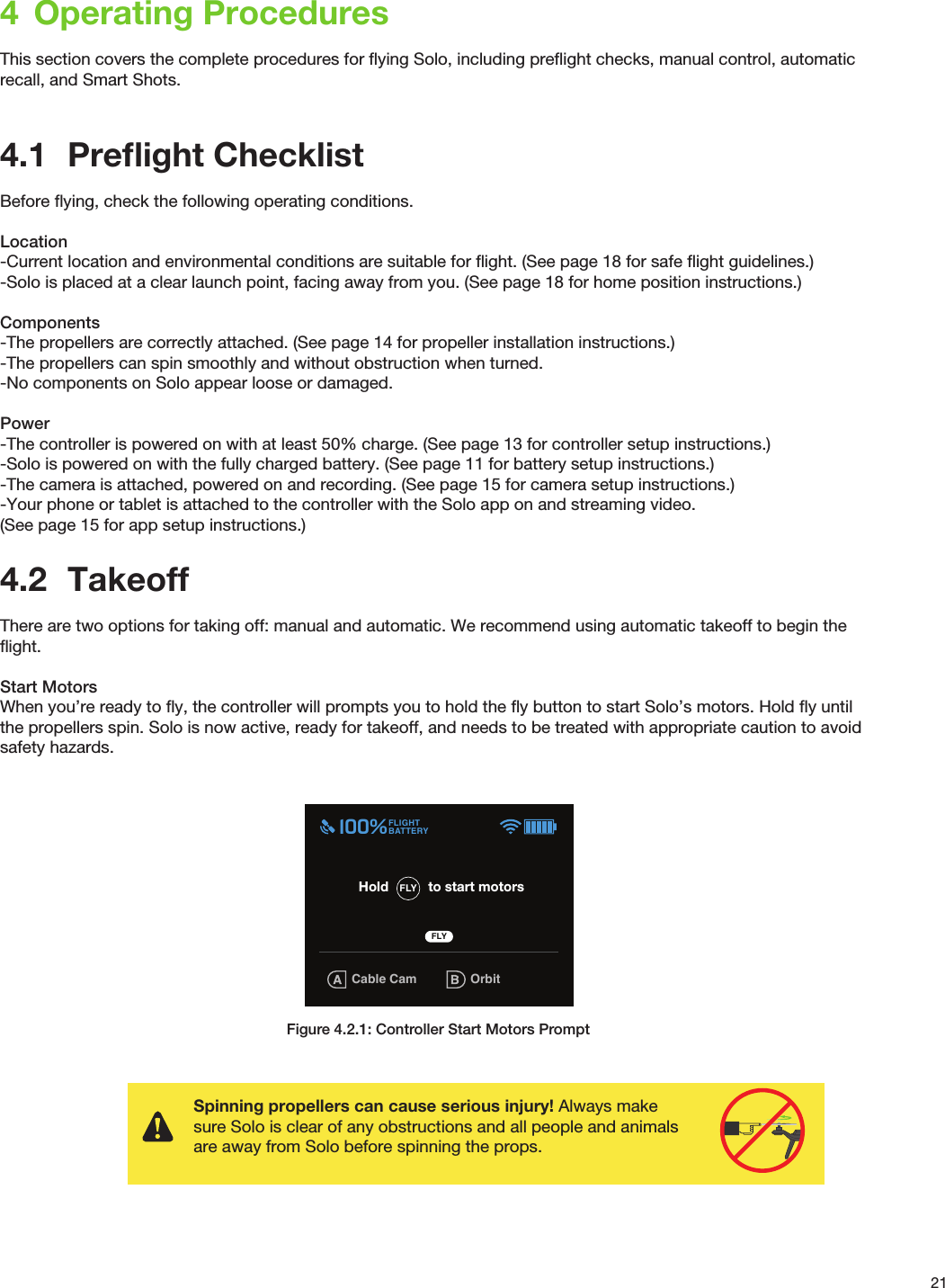
S111A User Manual
Users Manual
Navigation menu
Upload a User Manual
Namespaces
Wiki Guide
HTML
PDF
Info
Views
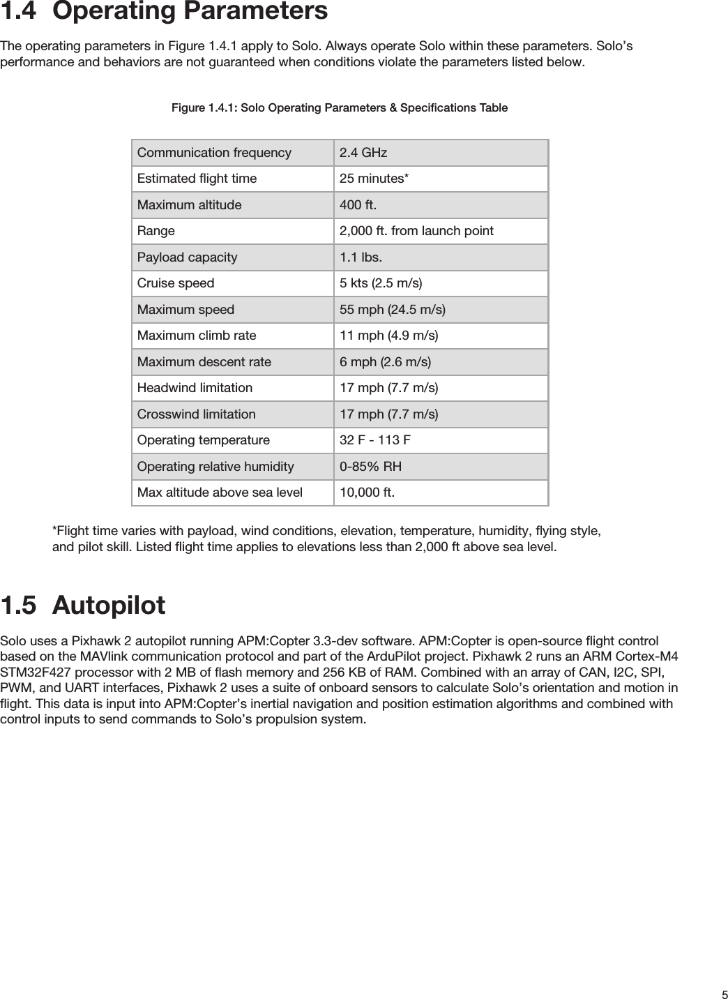
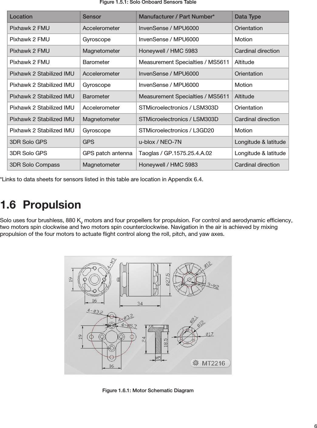
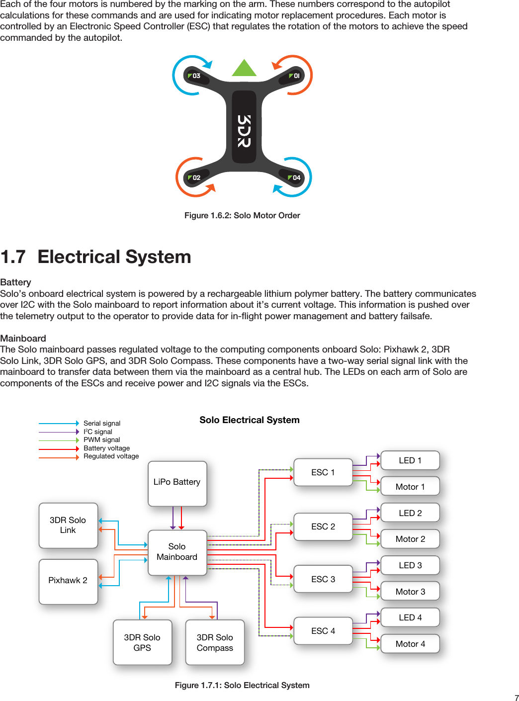
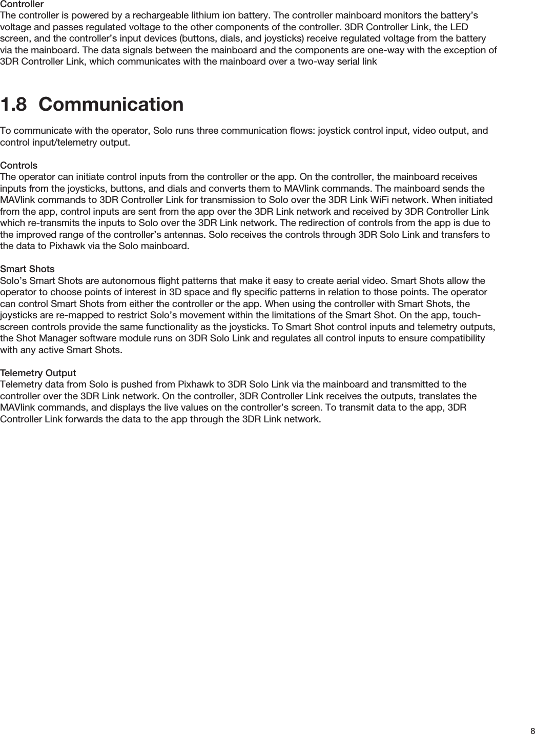
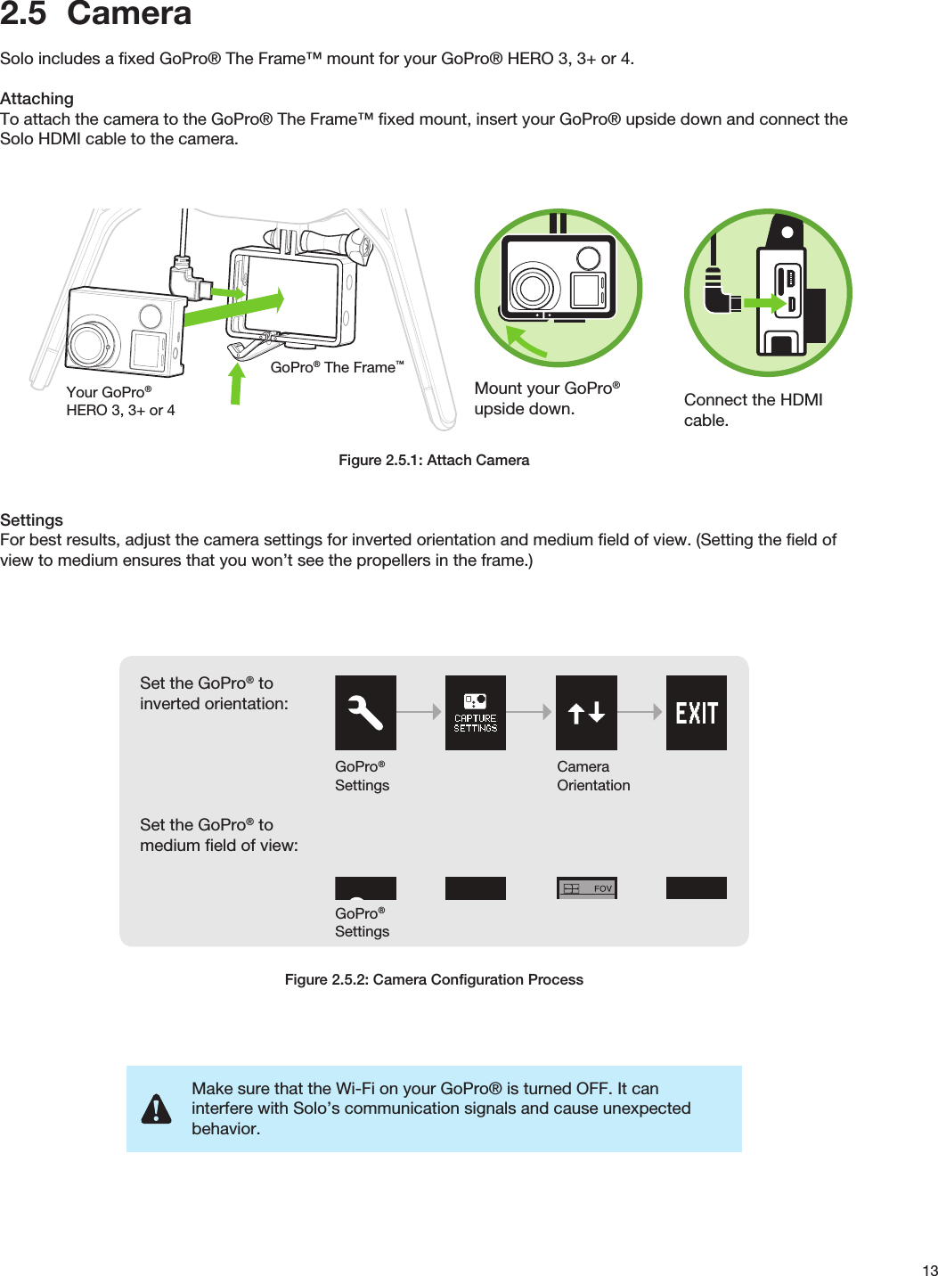
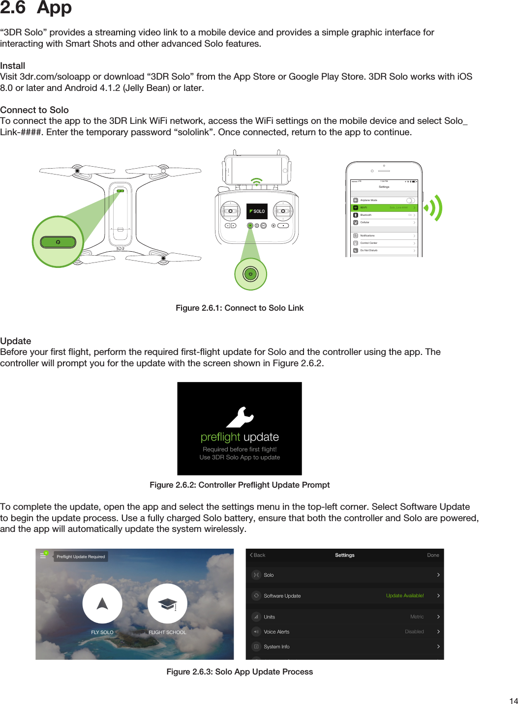
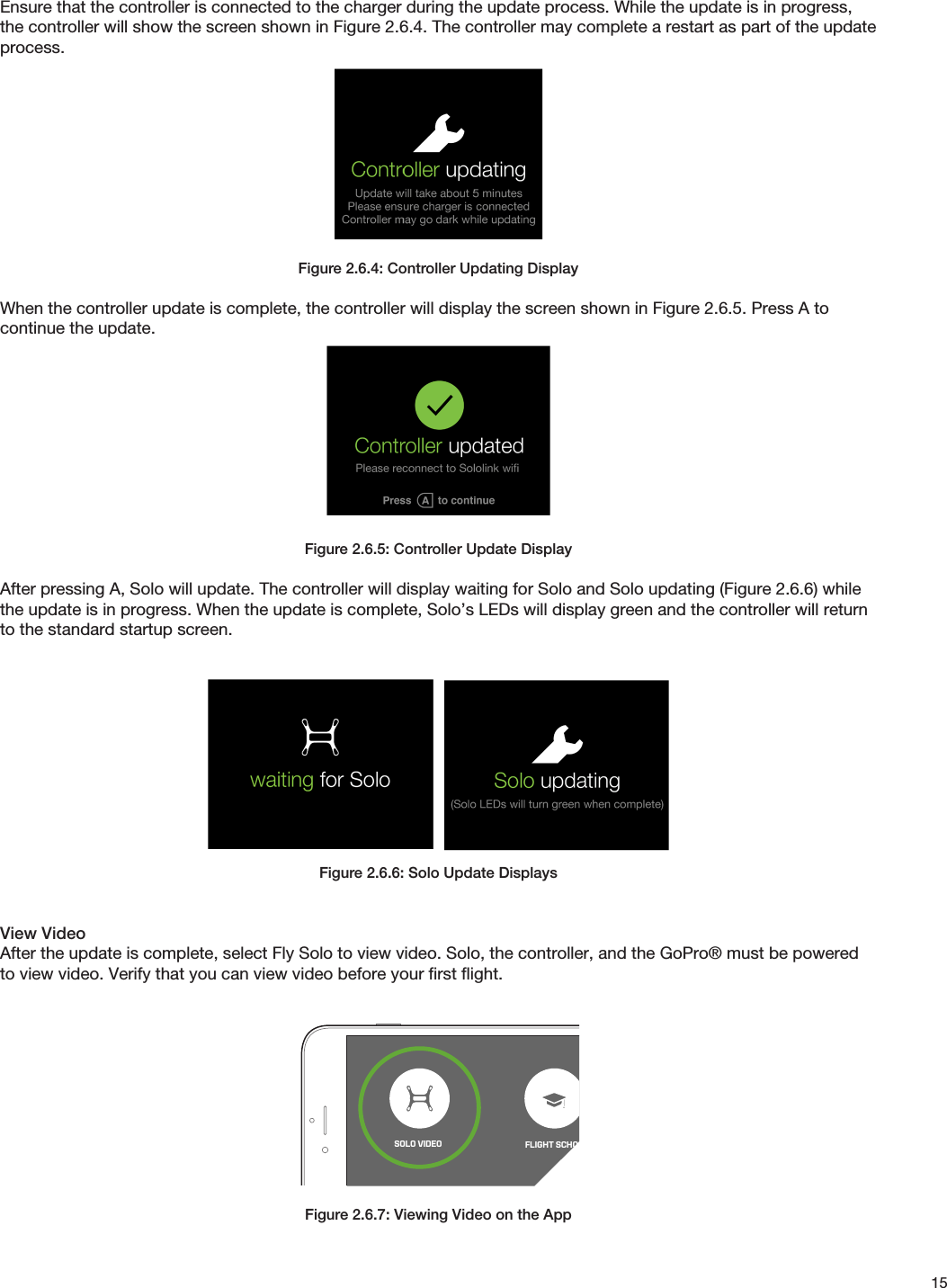
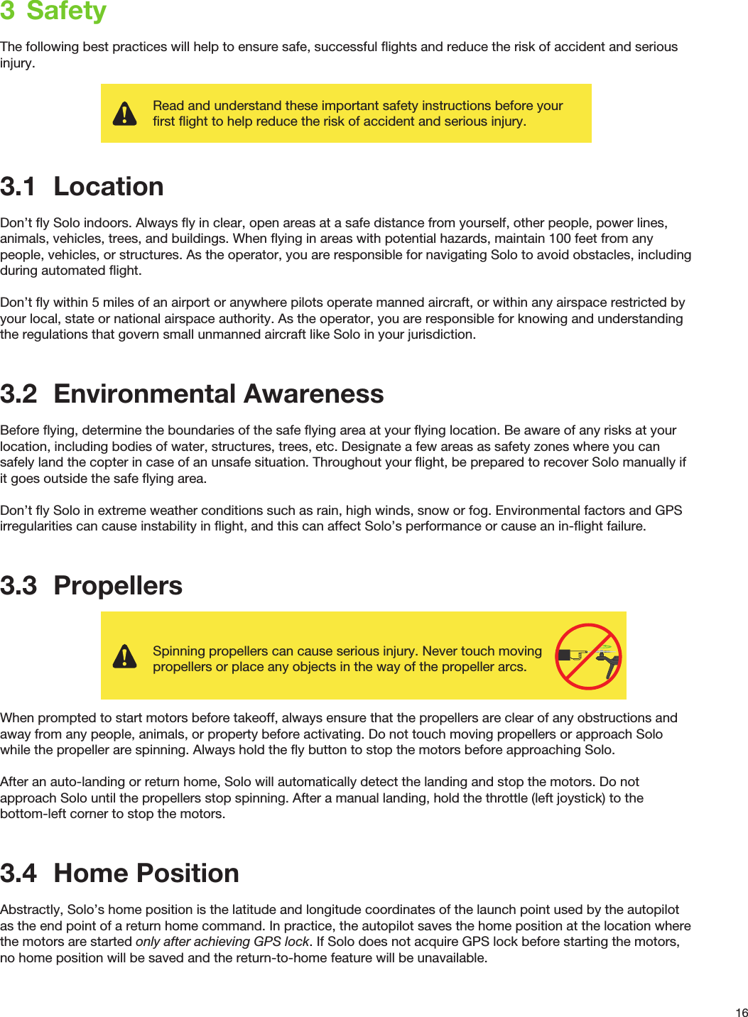
User Manual
Discussion / Help
Navigation