305 BROADCAST ETG150IS FM Broadcast Transmitter User Manual 2
305 BROADCAST, LLC FM Broadcast Transmitter 2
UserManual.wiki
>
305 BROADCAST
>
ETG150IS User Manual
>
User Manual 2
Contents
1.
User Manual 1
2.
User Manual 2
User Manual 2
Navigation menu
Upload a User Manual
Namespaces
Wiki Guide
HTML
PDF
Info
Views
User Manual
Discussion / Help
Navigation
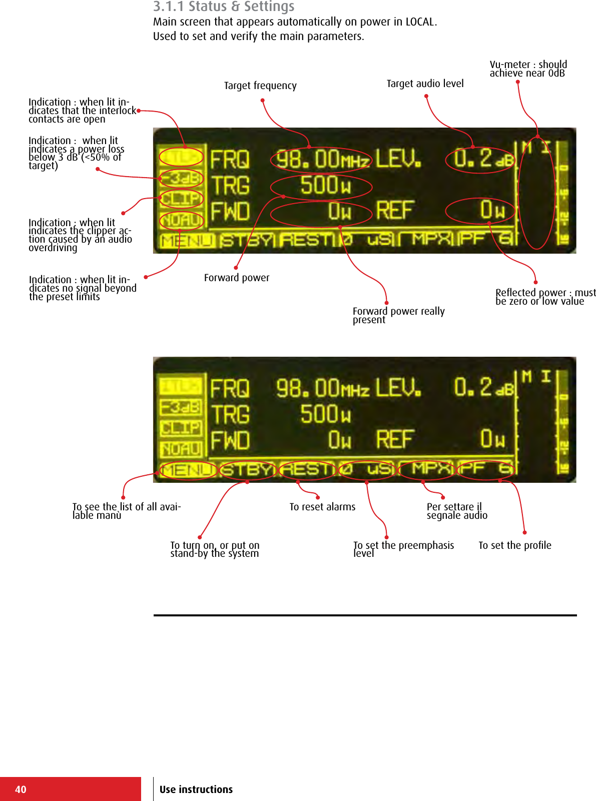
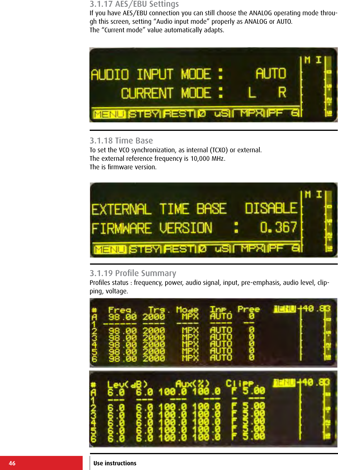
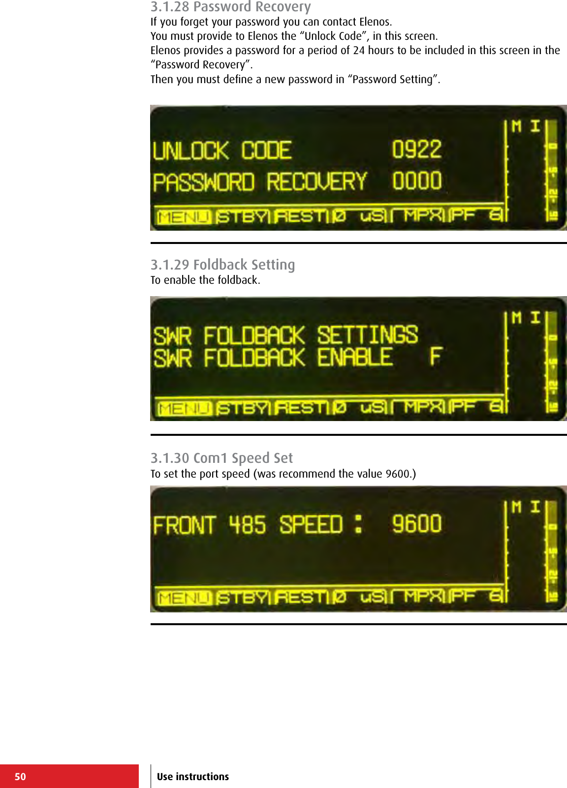
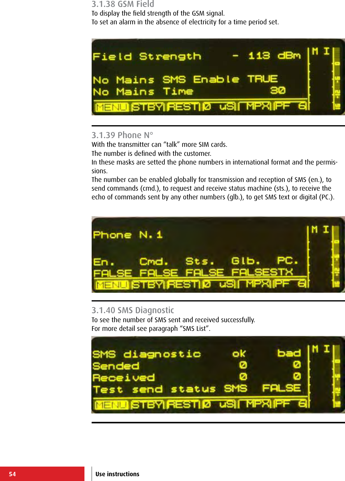
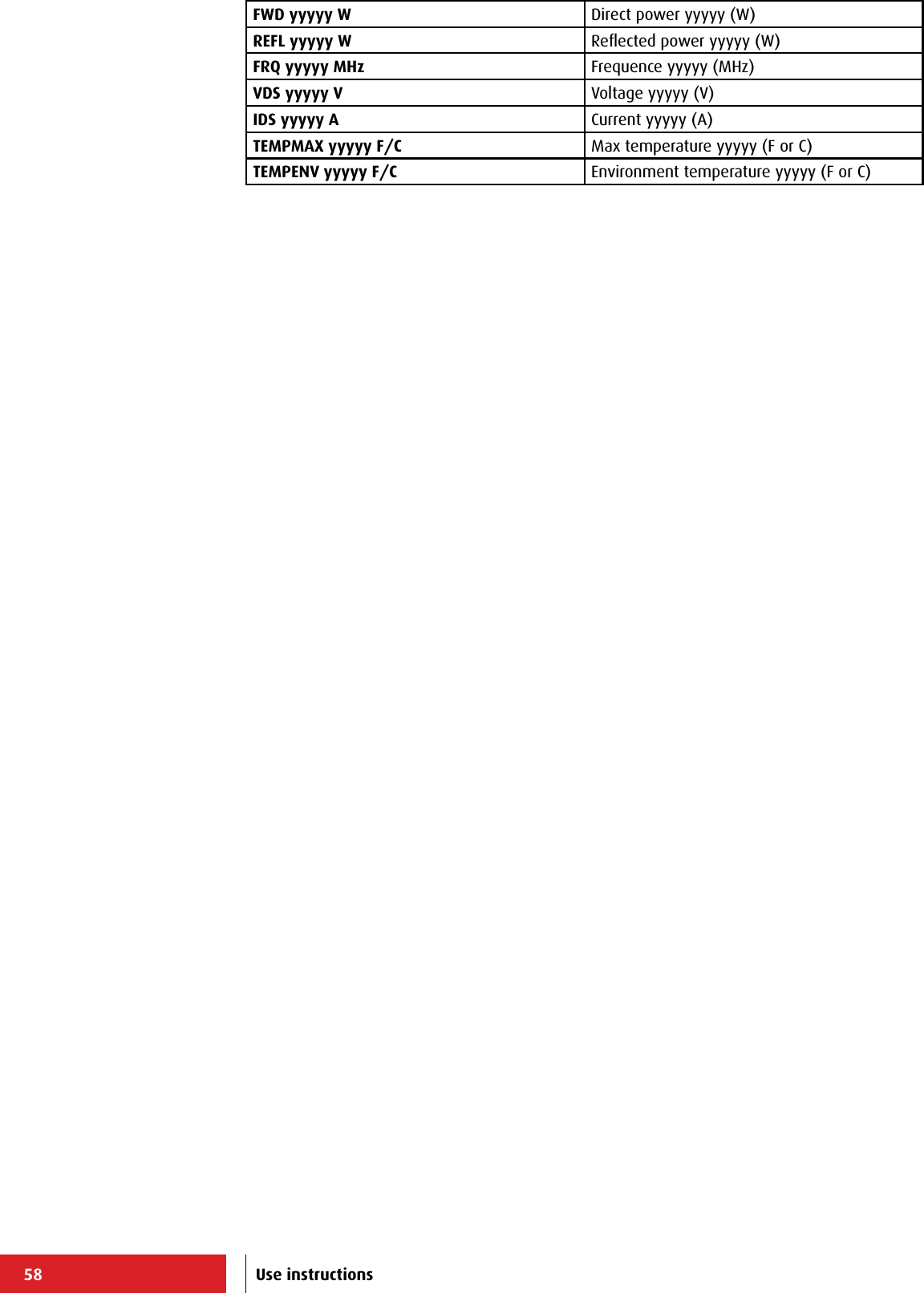
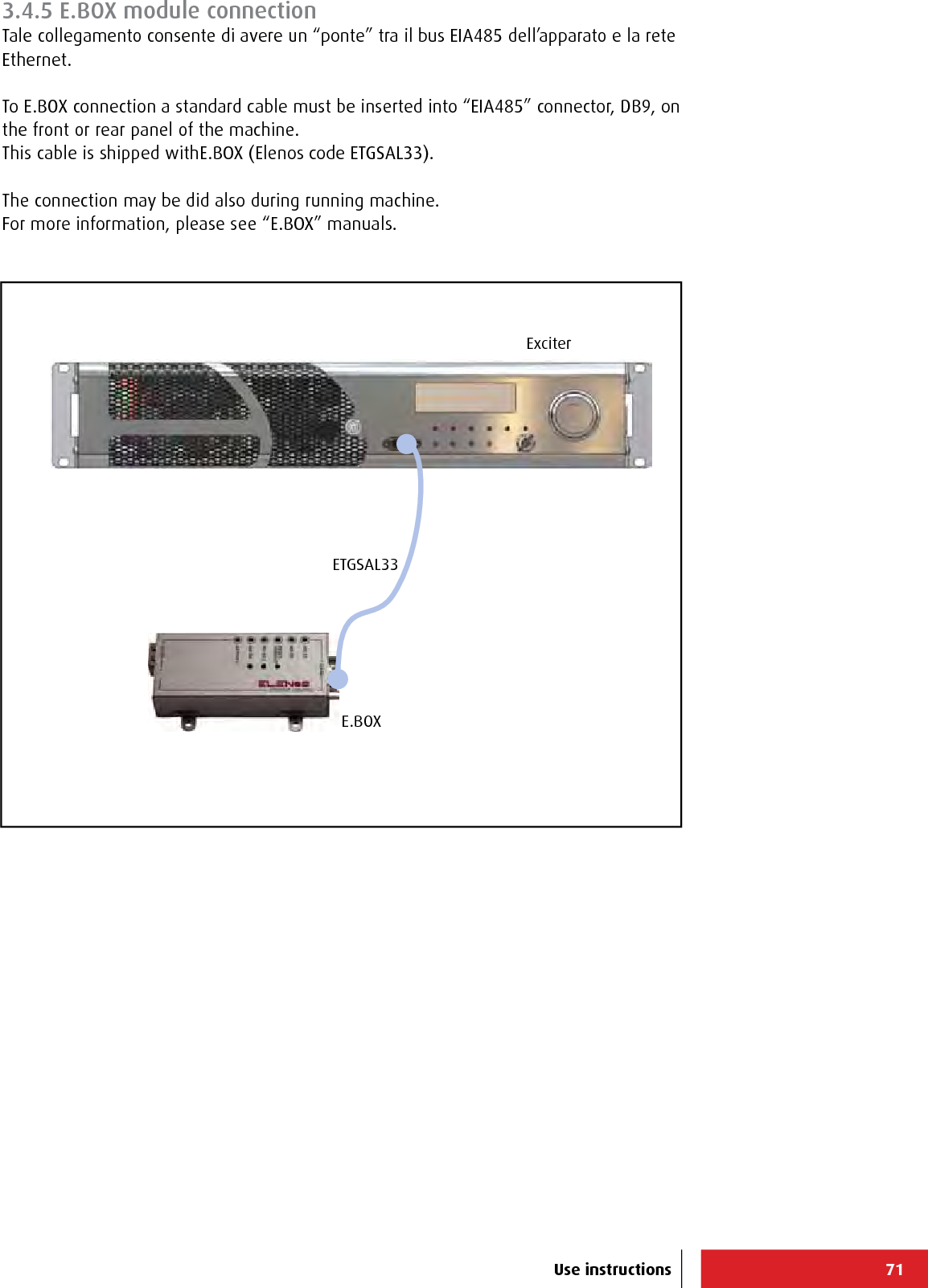
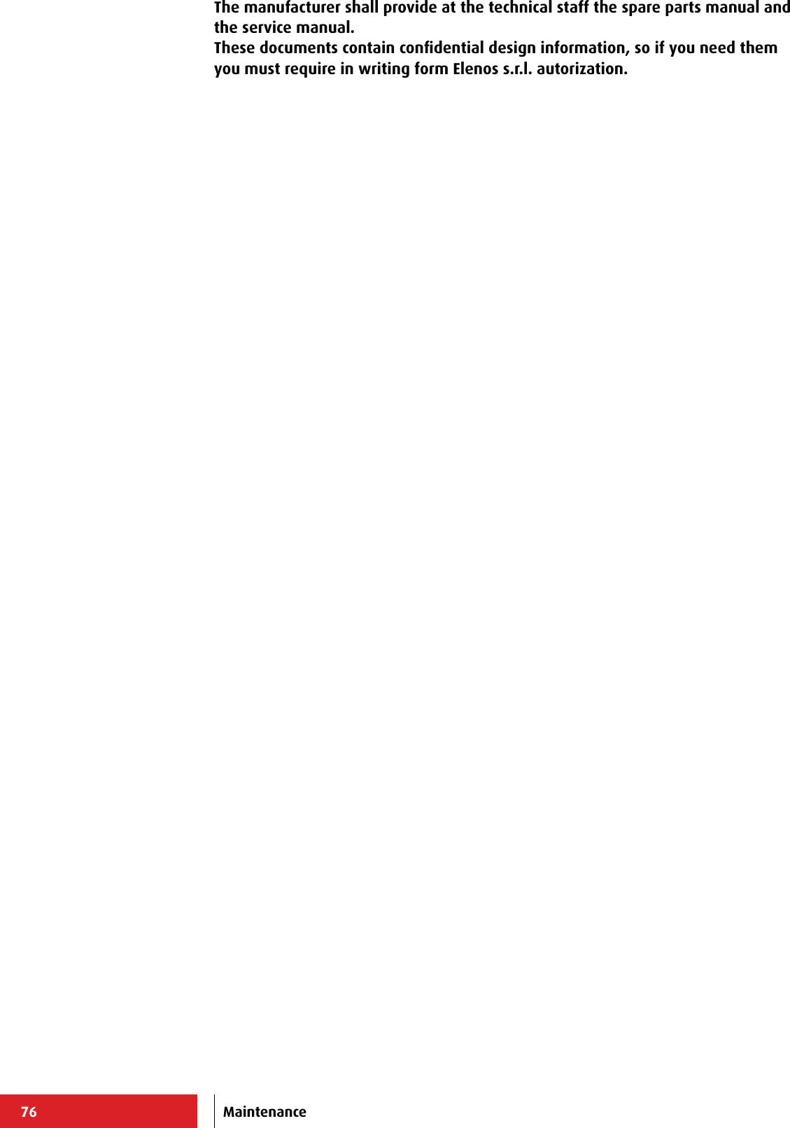
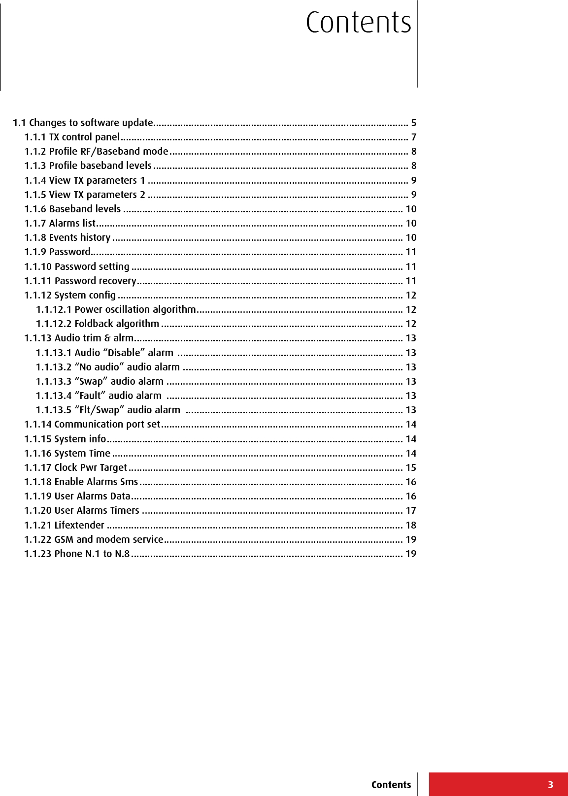
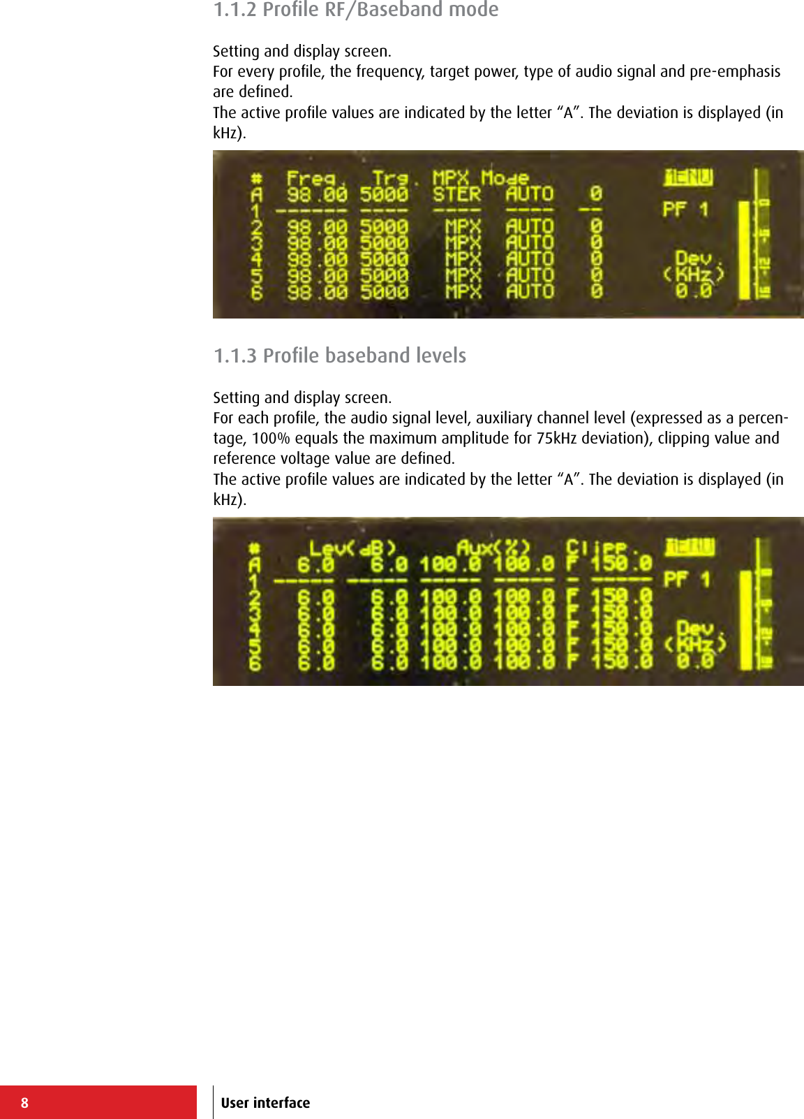
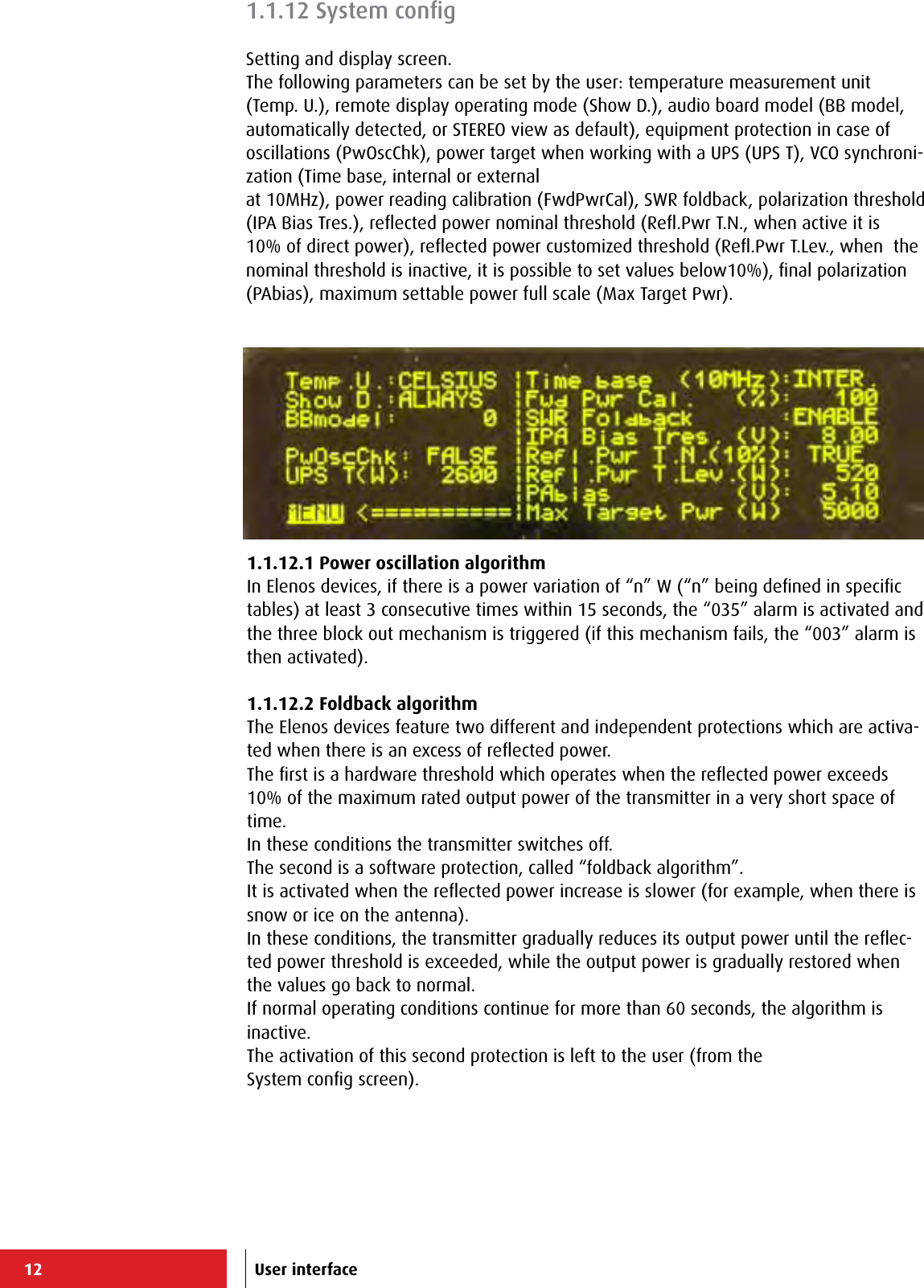
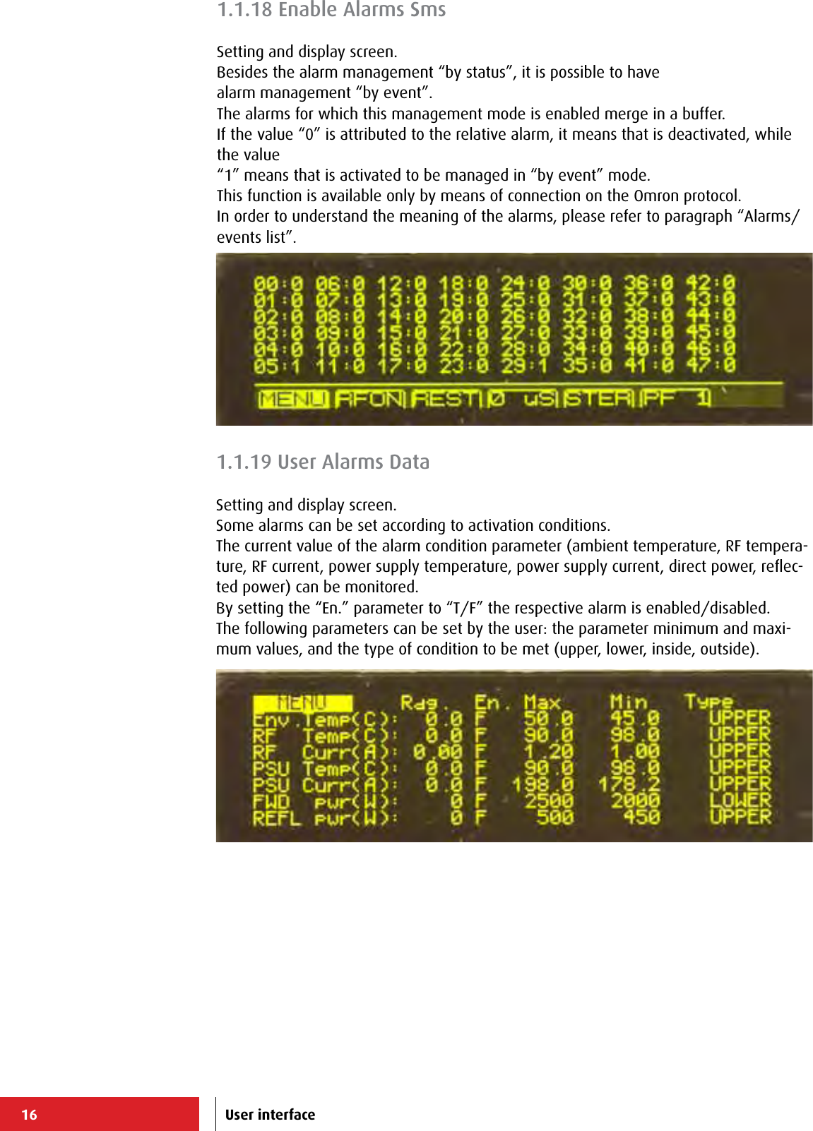
![60+-----------------------------------------------------------------------------+ | ELENOS ETG500_1P S/N.06SA0000 ELENOS <id 0000> life eXtender [menu=Q] | |-----------------------------------------------------------------------------| | Status : 004 STOP 08:52 08/07 | Reset alarms :F | |-----------------------------------------------------------------------------| | Forward (W): 0 [ 500] Frequency (MHz): 98.00 RF : STBY | | Reected (W): 0 LOCK ---- ---- ---- VDS (V): 0.0 | | Eff. (%): 0.0 Prof.#: 1 ---- ---- ---- STER IDS (A): 0.00 | |-----------------------------------------------------------------------------| | MAIN MENU (level 1) ====> 08:52:00 Fr 08/07/2011 | |-----------------------------------------------------------------------------| | M = Main RF data | | E = Exciter monitor +-----------------------------| | W = All data | E L E N O S Srl | | O = Proles | Via G.Amendola, 9 | | S = Status/Alarms | 44028 Poggio Renatico (FE) | | H = Events History | ITALY | | K = Password... | Tel.+39 0532 829965 | | Y = System... | Fax.+39 0532 829177 | | | www.elenos.com | | +-----------------------------| | Ver. 2.14 /1.07 (c)2011 Elenos| | | +-----------------------------------------------------------------------------+ +-----------------------------------------------------------------------------+ | ELENOS ETG500_1P S/N.06SA0000 ELENOS <id 0000> life eXtender [menu=Q] | |-----------------------------------------------------------------------------| | Status : 004 STOP 08:52 08/07 | Reset alarms :F | |-----------------------------------------------------------------------------| | Forward (W): 0 [ 500] Frequency (MHz): 98.00 RF : STBY | | Reected (W): 0 LOCK ---- ---- ---- VDS (V): 0.0 | | Eff. (%): 0.0 Prof.#: 1 ---- ---- ---- STER IDS (A): 0.00 | |-----------------------------------------------------------------------------| | MAIN RF DATA ====> | |-----------------------------------------------------------------------------| | VDS (V): 0.0 | | IDS (A): 0.00 | | DC power (W): 0 | | Efciency (%): 0.0 | | Temperatures(C): 30.5 | |-----------------------------------------------------------------------------| | Working Time : 0:19:52 >45C : 0:00:00 >50C : 0:00:00 | | Fans Working T.: 0:19:52 Reset : F | |-----------------------------------------------------------------------------| | Frequency (MHz): 98.00 [step 10kHz] | | Target PWR UPS (W) : 520 | | EEprom update N.: 49 5 115 On ram N.: 7 393 3 1618 | | 159 199 159 185 57 233 223 | +-----------------------------------------------------------------------------+ +-----------------------------------------------------------------------------+ | ELENOS ETG500_1P S/N.06SA0000 ELENOS <id 0000> life eXtender [menu=Q] | |-----------------------------------------------------------------------------| | Status : 004 STOP 08:52 08/07 | Reset alarms :F | |-----------------------------------------------------------------------------| |0(kHz) 15 30 45 60 75 90 105 115| |Mpx---[-20.00][ 7.3]-------+---------+---------+---------+---------+-------+ |> | |-20(dB) -15 -12 -9 -6 -3 0 3| |Right+[-40.83][ 0.4]-----+---------+---------+---------+---------+---------+ |> | |Left +[-40.83][ 0.4]-----+---------+---------+---------+---------+---------+ |> | | 0(kHz) 10.0 20.0 30.0 40.0 50.0 60.0 70.0 | |Aux---[ 0.0]------+---------+---------+---------+---------+---------+------+ |> | |-----------------------------------------------------------------------------| | Tx Frequency(MHz): 98.00 | |-----------------------------------------------------------------------------| | Gain level (dB): 0.2 | Mode : Stereo | SW Ver: 0.367 | | | Pilot level : 10.00 | | | Level L = R: TRUE | Pilot phase : 0.0 | | | Aux1(%):100.0 Aux2(%):100.0 | Preenphasys (uS): 0 | Pll : LOCK | +-----------------------------------------------------------------------------+ Main MenuMain MenùMain RF Data (M)Main Menù Exciter Monitor (E)Use instructions3.4.1.1 Hyperterminal screen](https://usermanual.wiki/305-BROADCAST/ETG150IS.User-Manual-2/User-Guide-2906741-Page-27.png)
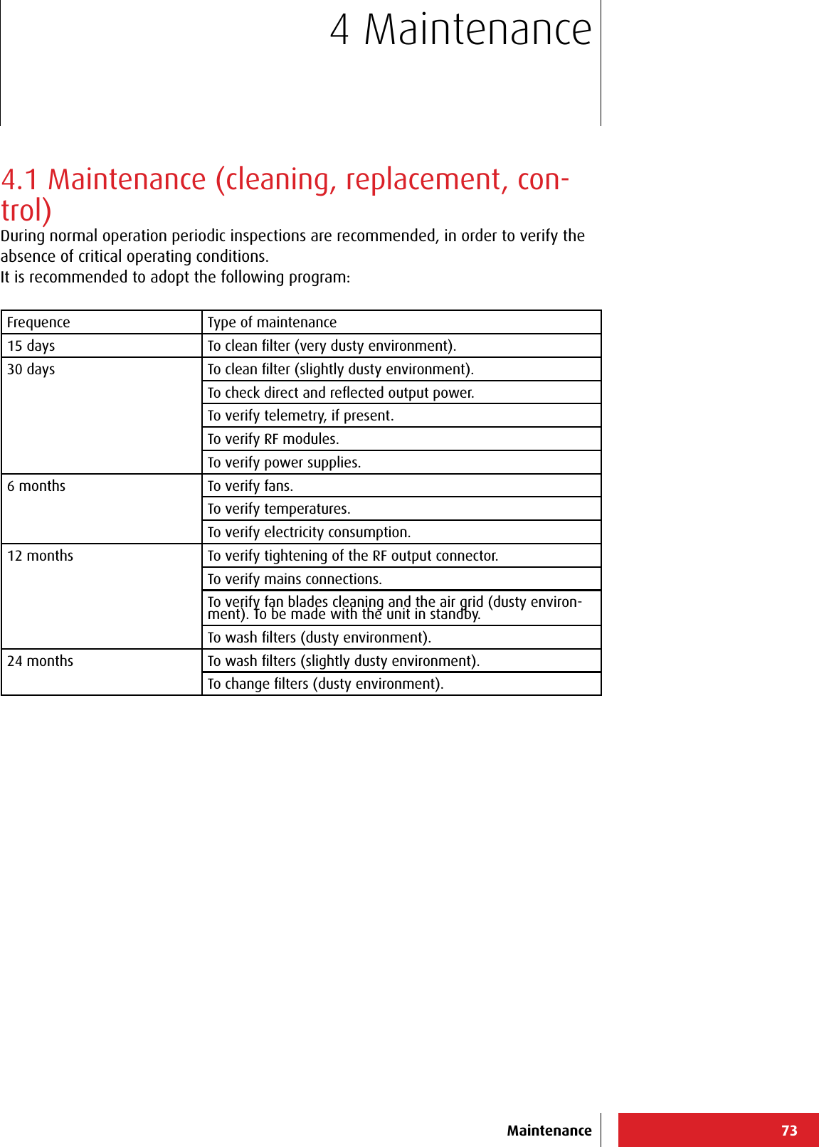
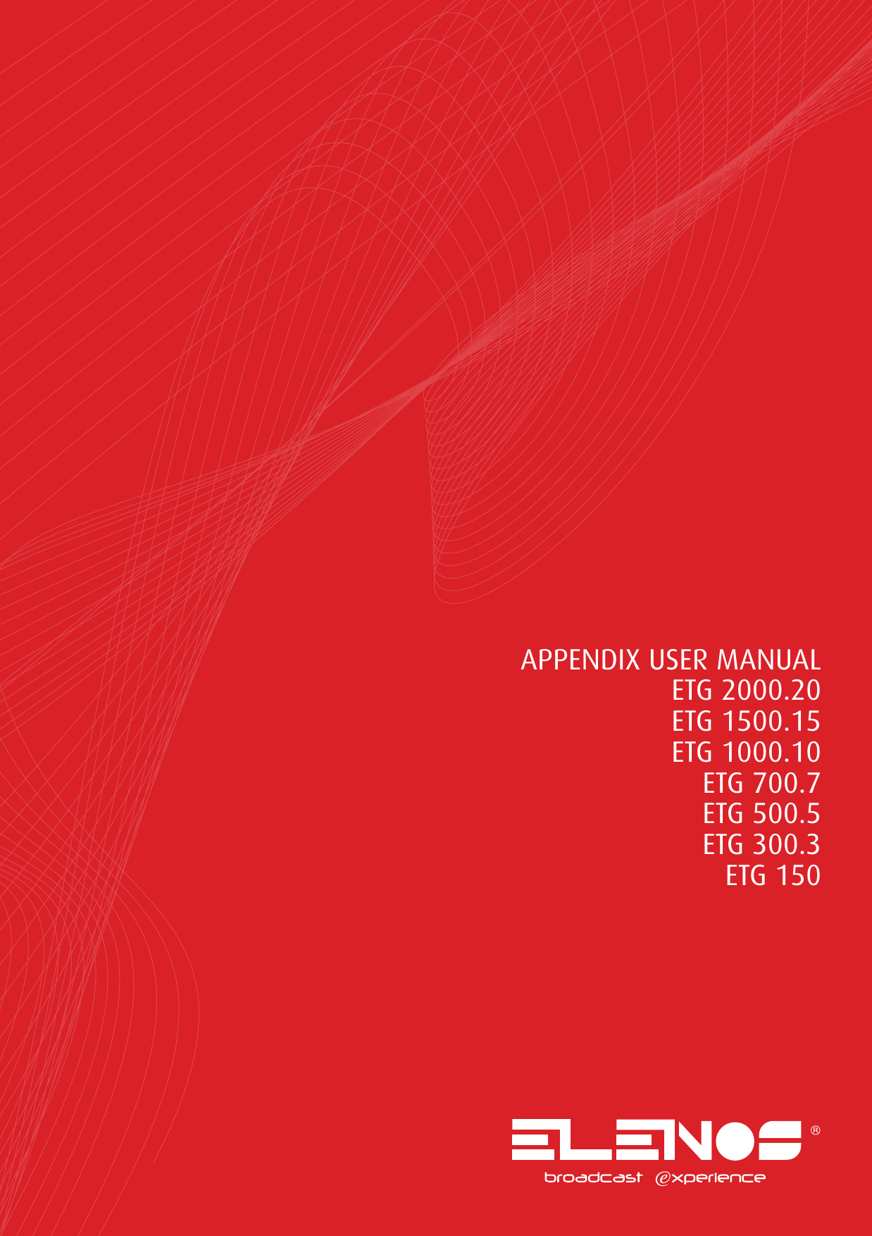
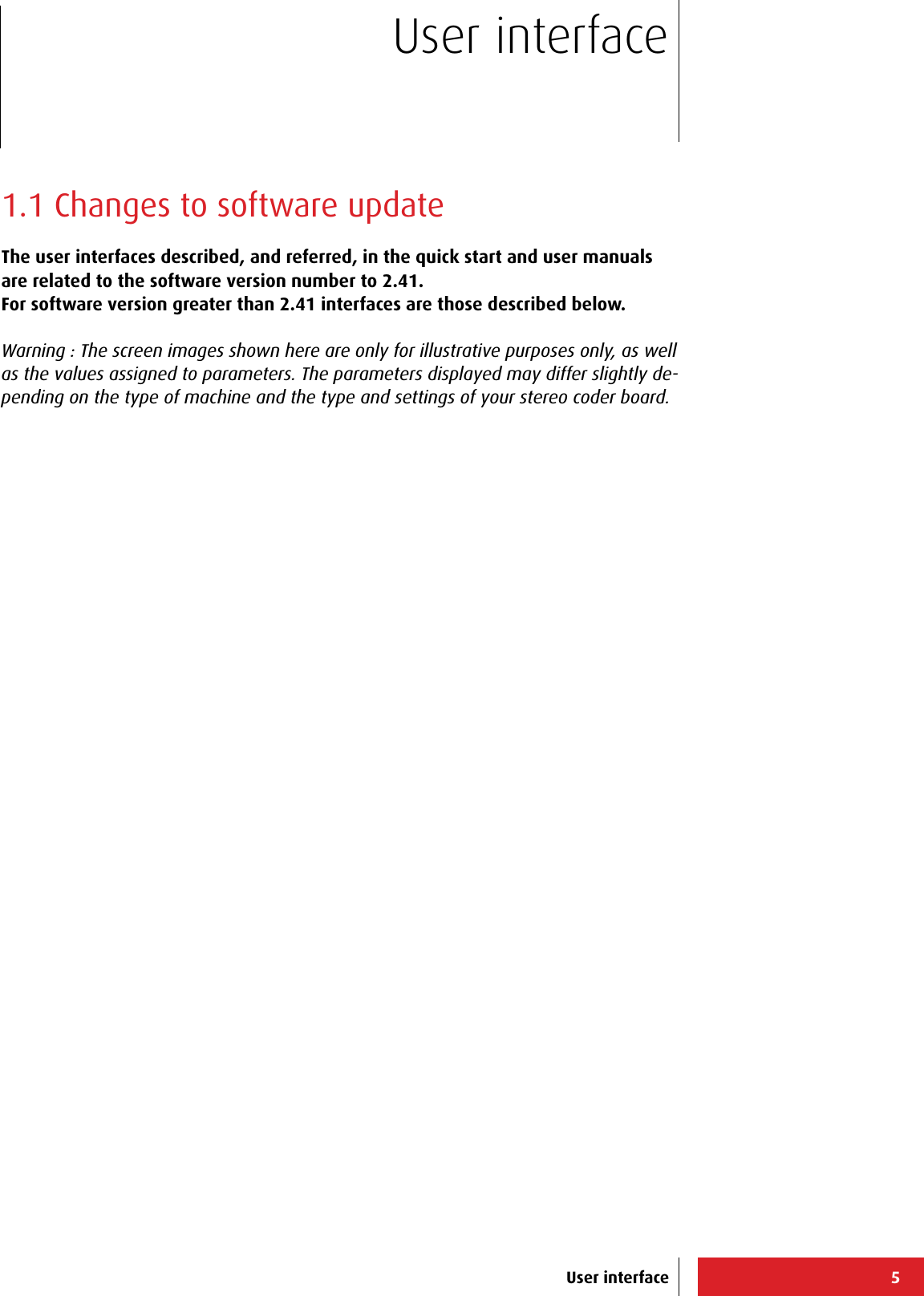
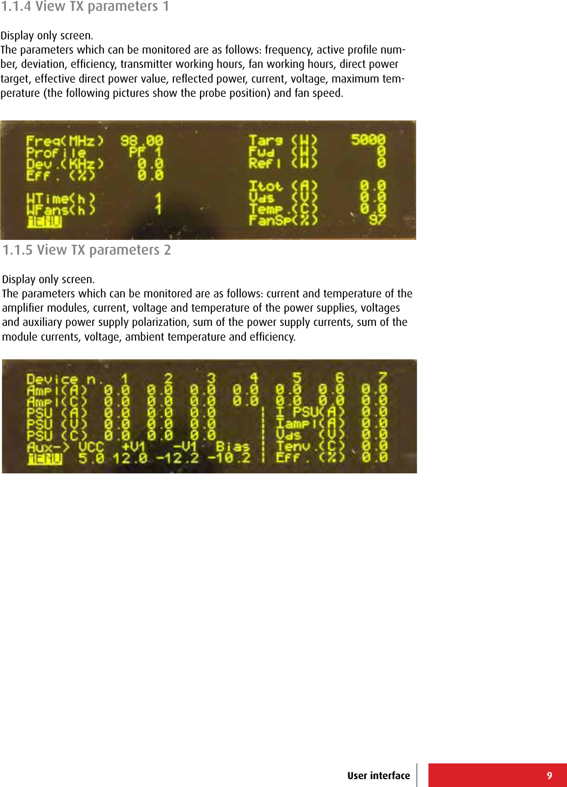
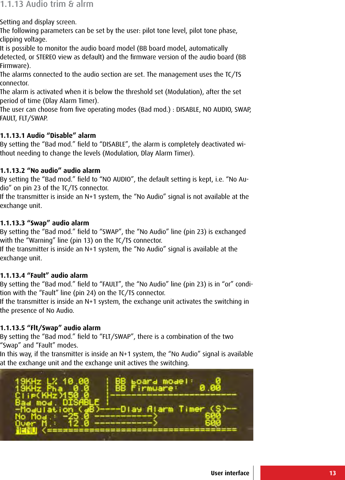
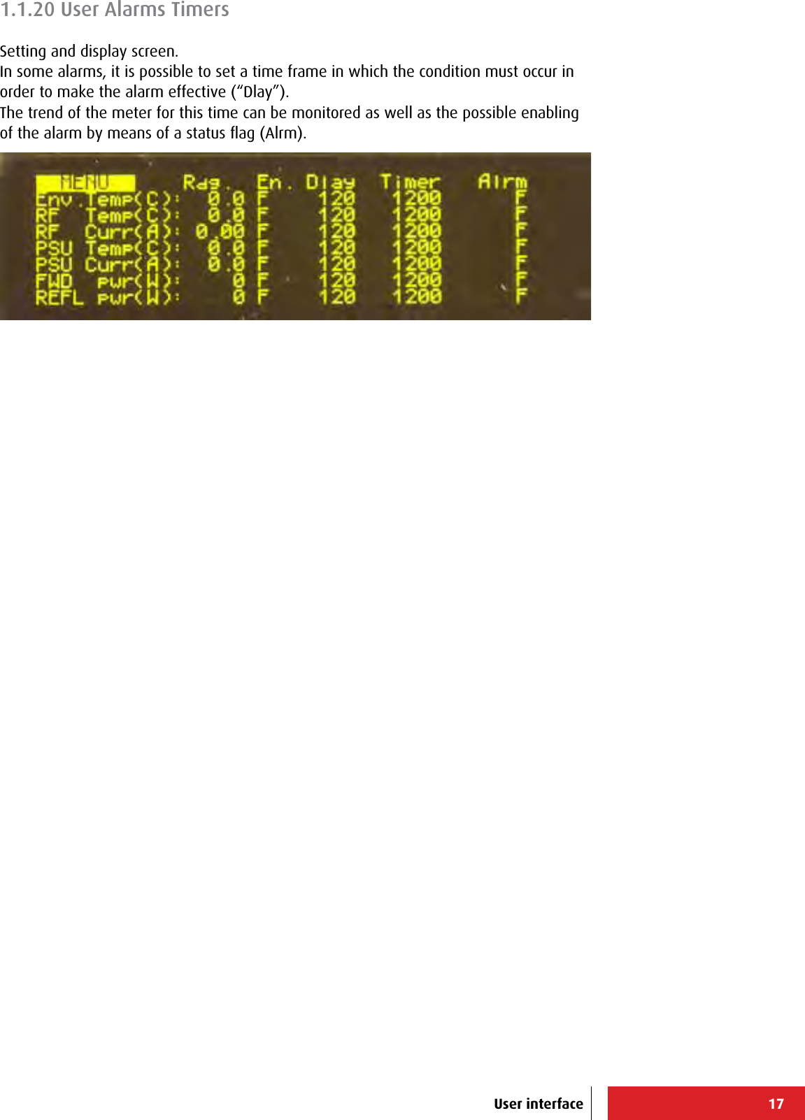
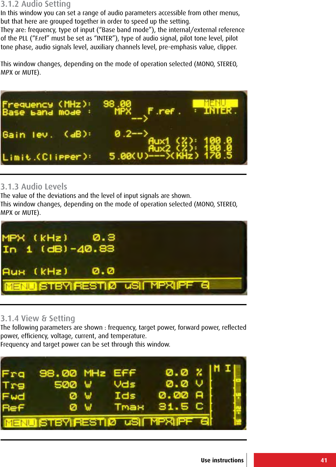
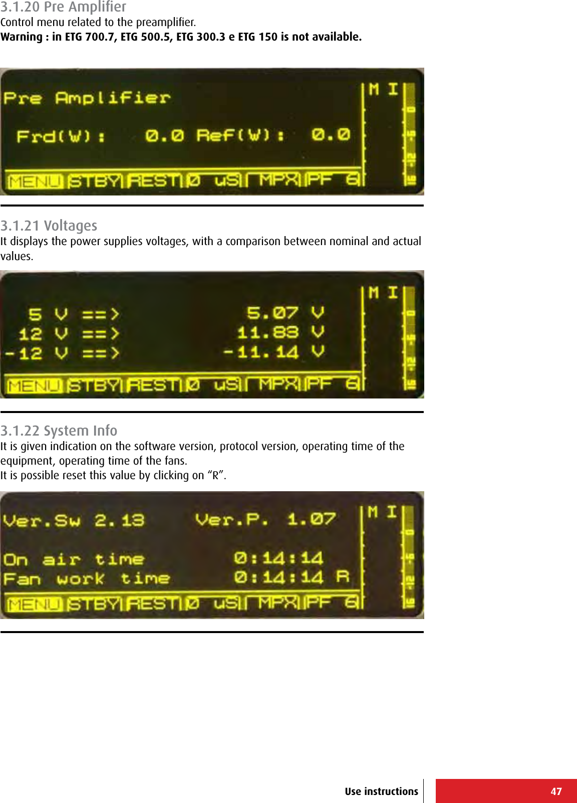
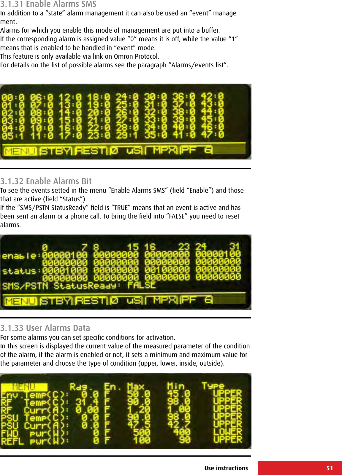
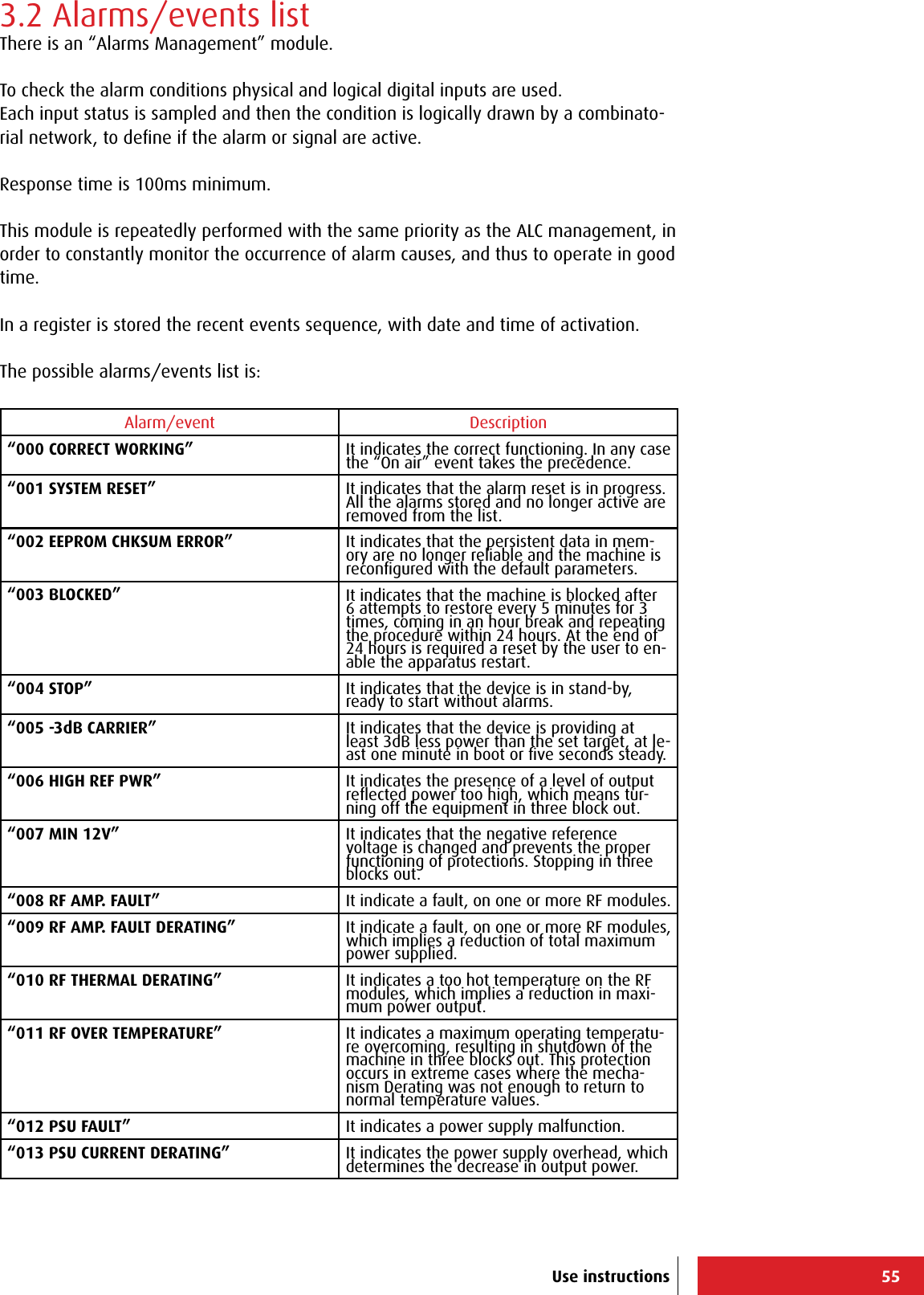
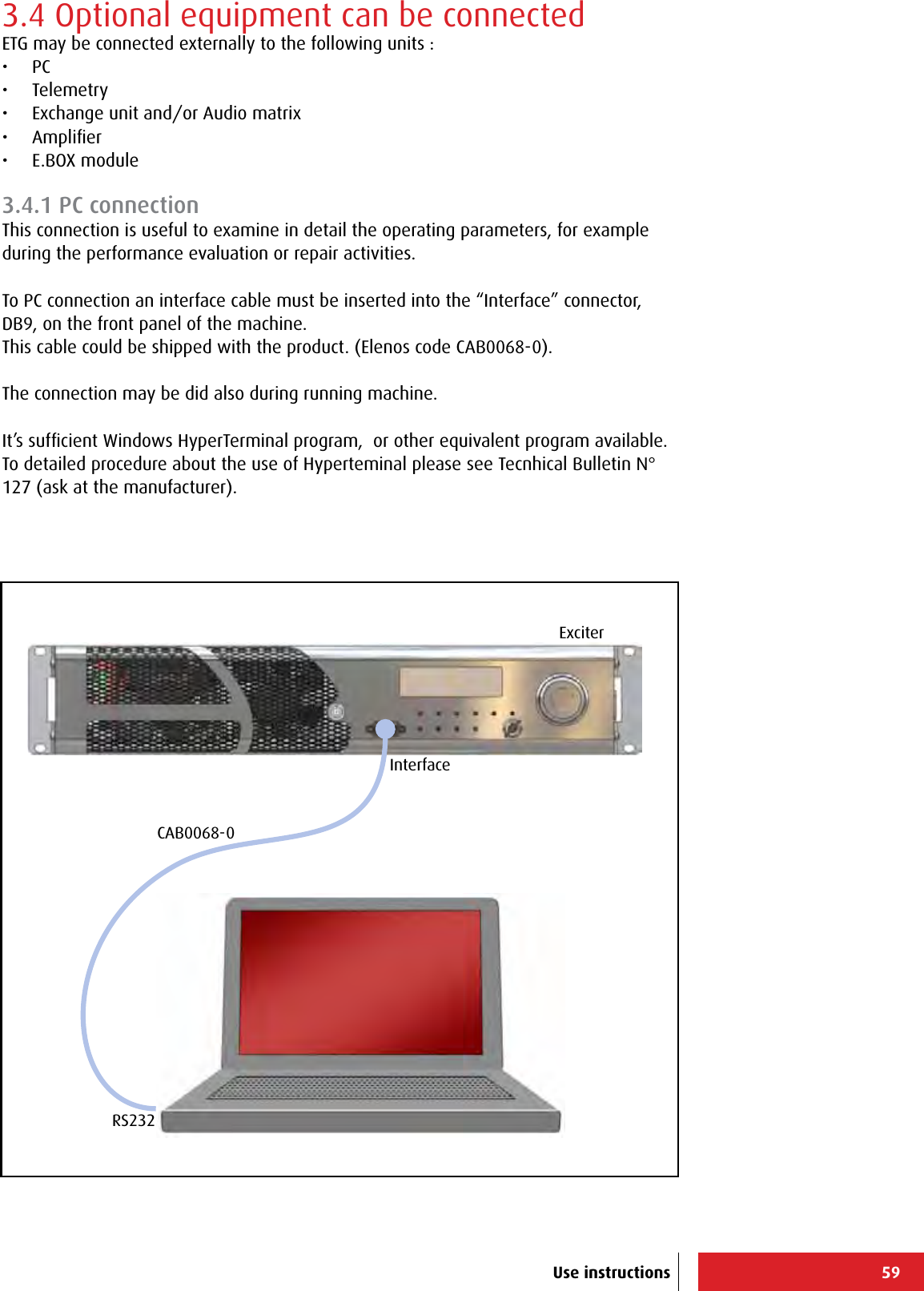
![61+-----------------------------------------------------------------------------+ | ELENOS ETG500_1P S/N.06SA0000 ELENOS <id 0000> life eXtender [menu=Q] | |-----------------------------------------------------------------------------| | Status : 004 STOP 08:52 08/07 | Reset alarms :F | |-----------------------------------------------------------------------------| | RF CURRENTS (A) Sum: 0.00 | |Mod n: 1 | |Id: 0.00 | |-----------------------------------------------------------------------------| | Psu 1 (A): 0.0 Vcc (5V): 5.09 | STAND-BY : TRUE | | V+ (12V): 11.89 | FREQUENCY(MHz): 98.00 | | V- (12V): 11.17 | TARGET PWR (W): 500 | | Ids (A): 0.0 VBias (V):-10.24 |-----------------------------------| | Vds_PSU (V): 0.0 Vds (V): 0.0 |TEMPERATURES (C) Rf 1 : 30.5 | | | Max RF : 30.5 | |-----------------------------------------| | | Fwd (W): 0 PreA Fwd (W): 0.0 | Max PSU: 0.0 | | Ref (W): 0 | Psu 1 : 0.0 | | Eff (%): 0.0 | | |-----------------------------------------| | | | | | WORKING TIME : 0:19:52 | | | FAN WORKING T.: 0:19:52 | Fan s.%: 0 | +-----------------------------------------------------------------------------+ +-----------------------------------------------------------------------------+ | ELENOS ETG500_1P S/N.06SA0000 ELENOS <id 0000> life eXtender [menu=Q] | |-----------------------------------------------------------------------------| | Status : 004 STOP 08:52 08/07 | Reset alarms :F | |-----------------------------------------------------------------------------| | Forward (W): 0 [ 500] Frequency (MHz): 98.00 RF : STBY | | Reected (W): 0 LOCK ---- ---- ---- VDS (V): 0.0 | | Eff. (%): 0.0 Prof.#: 1 ---- ---- ---- STER IDS (A): 0.00 | |-----------------------------------------------------------------------------| | L e v e l s Clipping | | # Frequency Target Mode Input Right Left Aux1 Aux2 Pree Enab. Lev.| | MHz W dB dB % % uS V | |Cur. 98.00 500 Stereo AUTO 0.2 0.2 100.0 100.0 0 OFF 5.00 | | | | 1 ------ ---- ------- ------- ---- ---- ----- ----- -- --- ---- | | 2 98.00 550 Ext.MPX AUTO 6.0 6.0 100.0 100.0 0 OFF 5.00 | | 3 98.00 550 Ext.MPX AUTO 6.0 6.0 100.0 100.0 0 OFF 5.00 | | 4 98.00 550 Ext.MPX AUTO 6.0 6.0 100.0 100.0 0 OFF 5.00 | | 5 98.00 550 Ext.MPX AUTO 6.0 6.0 100.0 100.0 0 OFF 5.00 | | 6 98.00 550 Ext.MPX AUTO 6.0 6.0 100.0 100.0 0 OFF 5.00 | | | | Current Prole # : 1 | | Delta F (+/- KHz): 7.3 | +-----------------------------------------------------------------------------+ +-----------------------------------------------------------------------------+ | ELENOS ETG500_1P S/N.06SA0000 ELENOS <id 0000> life eXtender [menu=Q] | |-----------------------------------------------------------------------------| | Status : 004 STOP 08:52 08/07 | Reset alarms :F | |-----------------------------------------------------------------------------| | STATUS/ALARMS (1 - 17) ==> | | ACTIVE 004 STOP | | 044 OUT PWR NOT VERIFIED | | 045 UPS ACTIVE | | 005 -3dB CARRIER | | | | | | | | | | | | | | | | | | | | | | | | | | | +-----------------------------------------------------------------------------+ Main MenùAll Data (W)Main Menù Profiles (O)Main Menù Status/Alarms(S)Highlighted parameters not present in ETG 150, ETG 300.3, ETG 500.5 and ETG 700.7Use instructions](https://usermanual.wiki/305-BROADCAST/ETG150IS.User-Manual-2/User-Guide-2906741-Page-28.png)
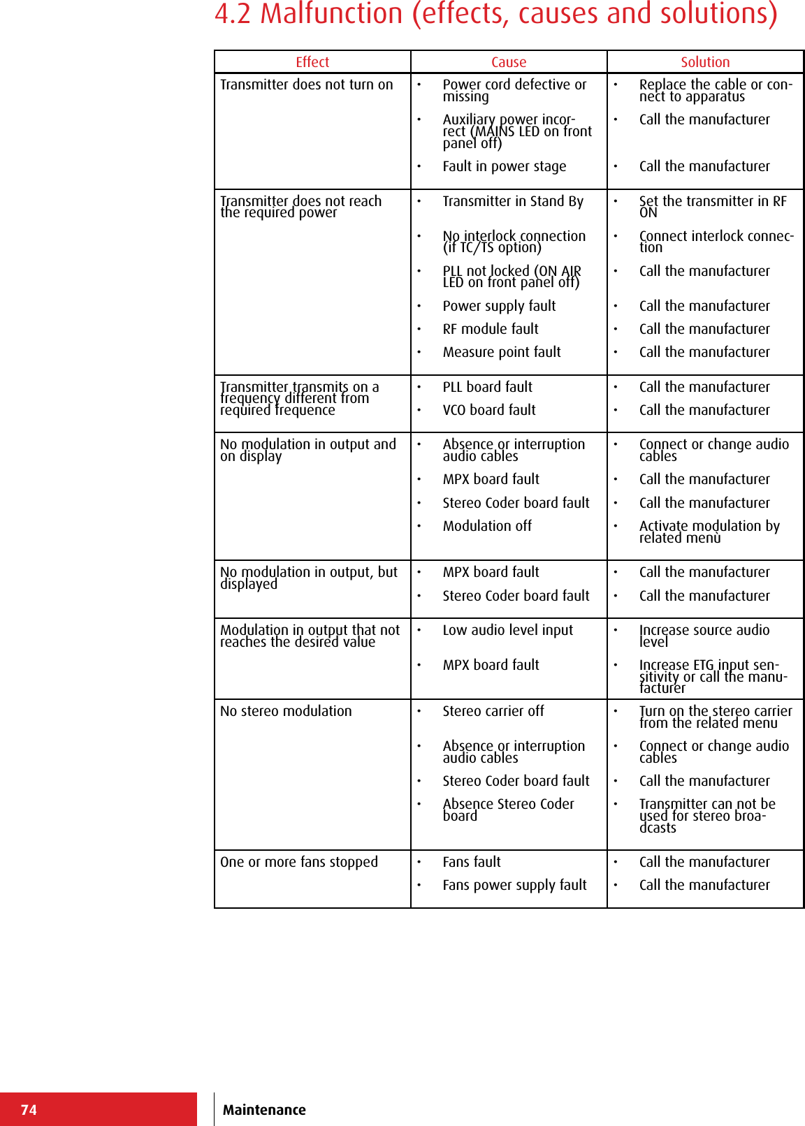
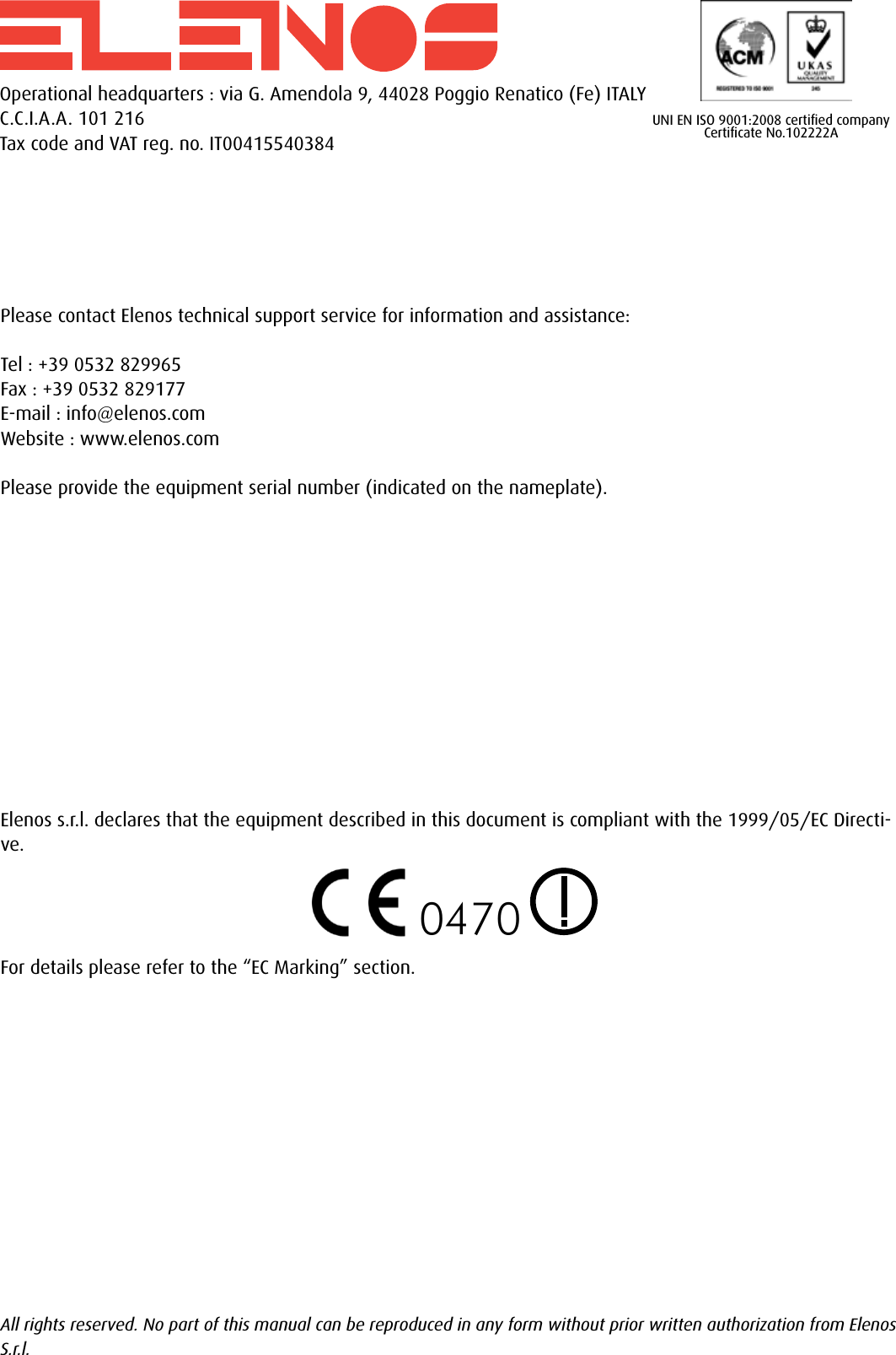
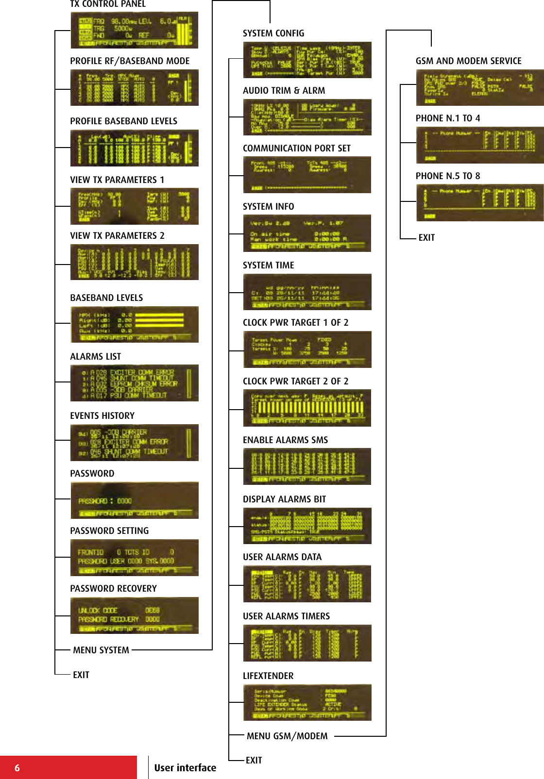
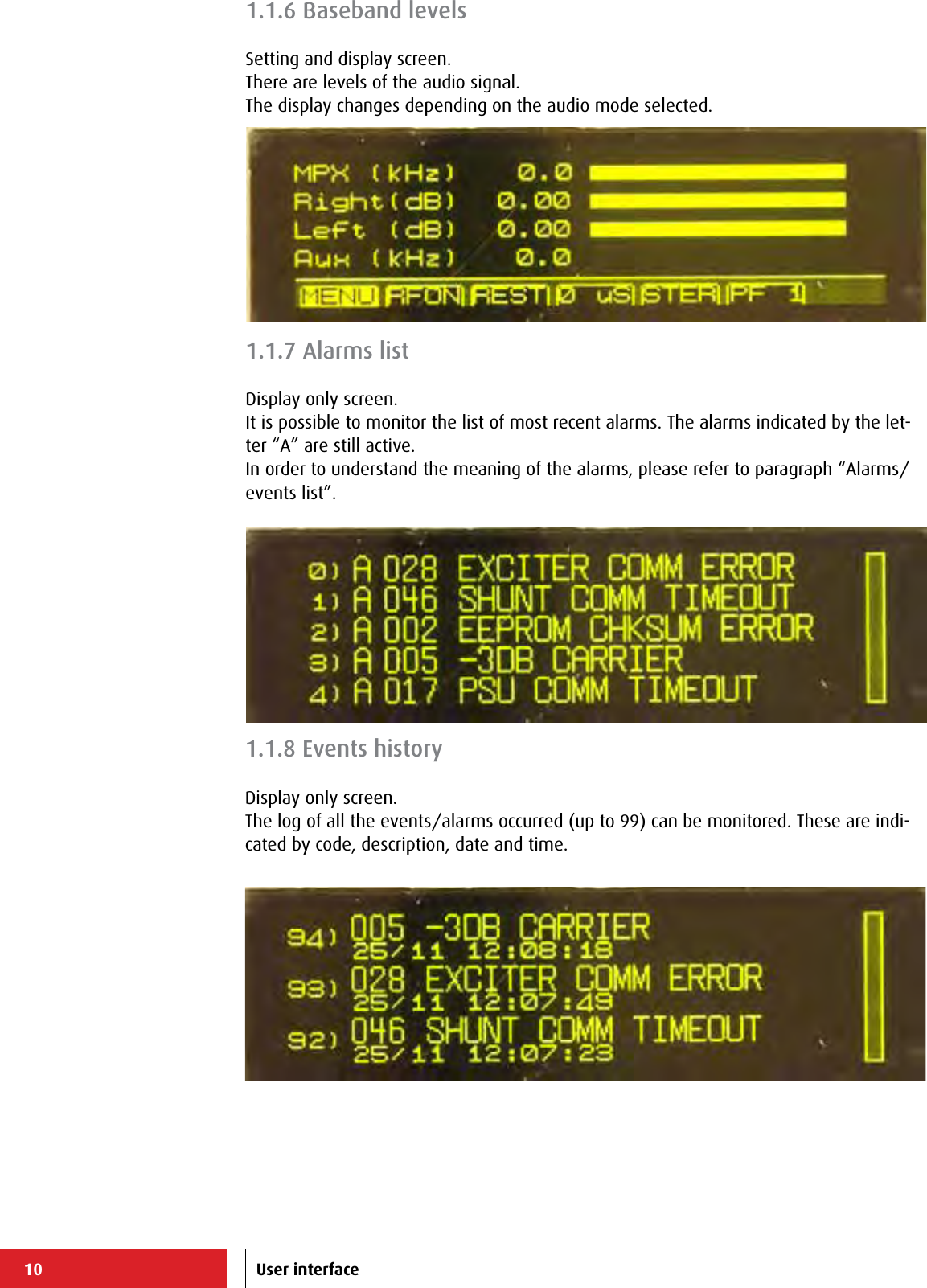
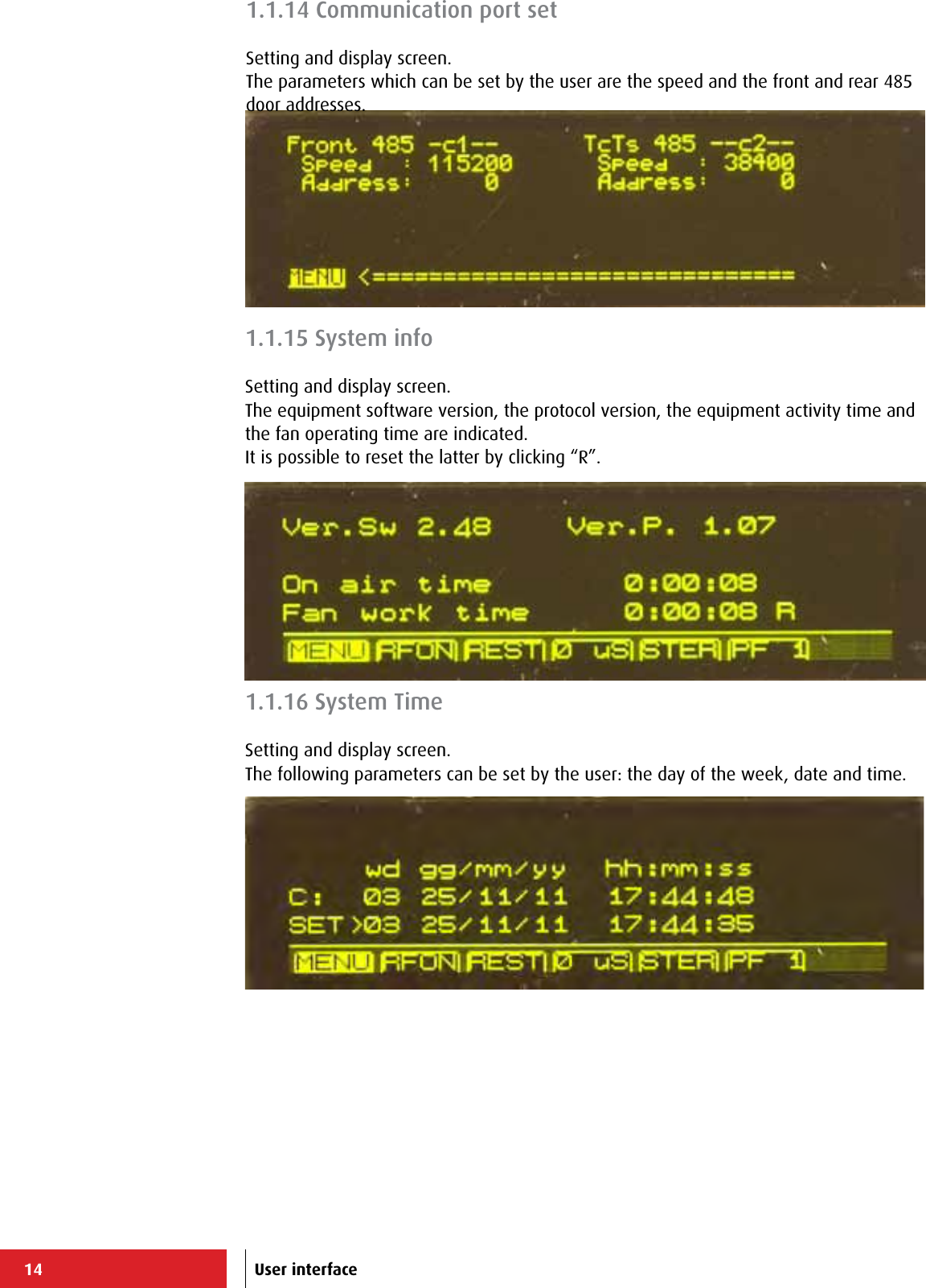
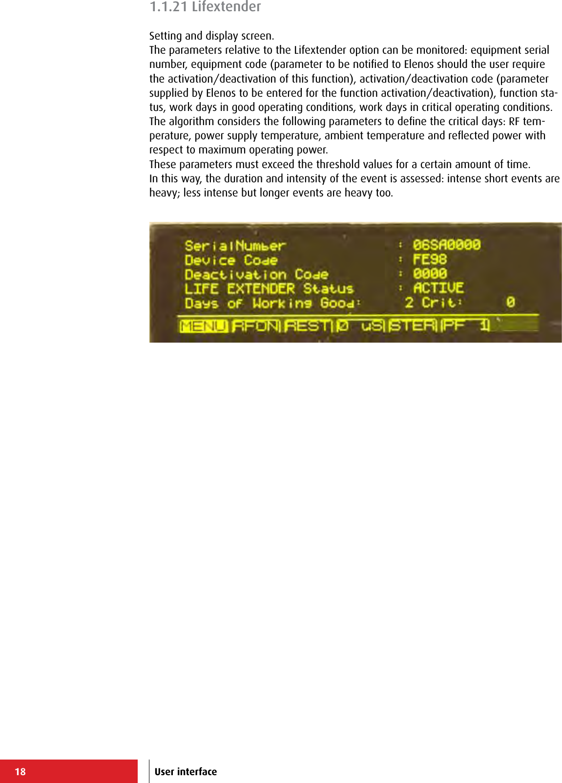
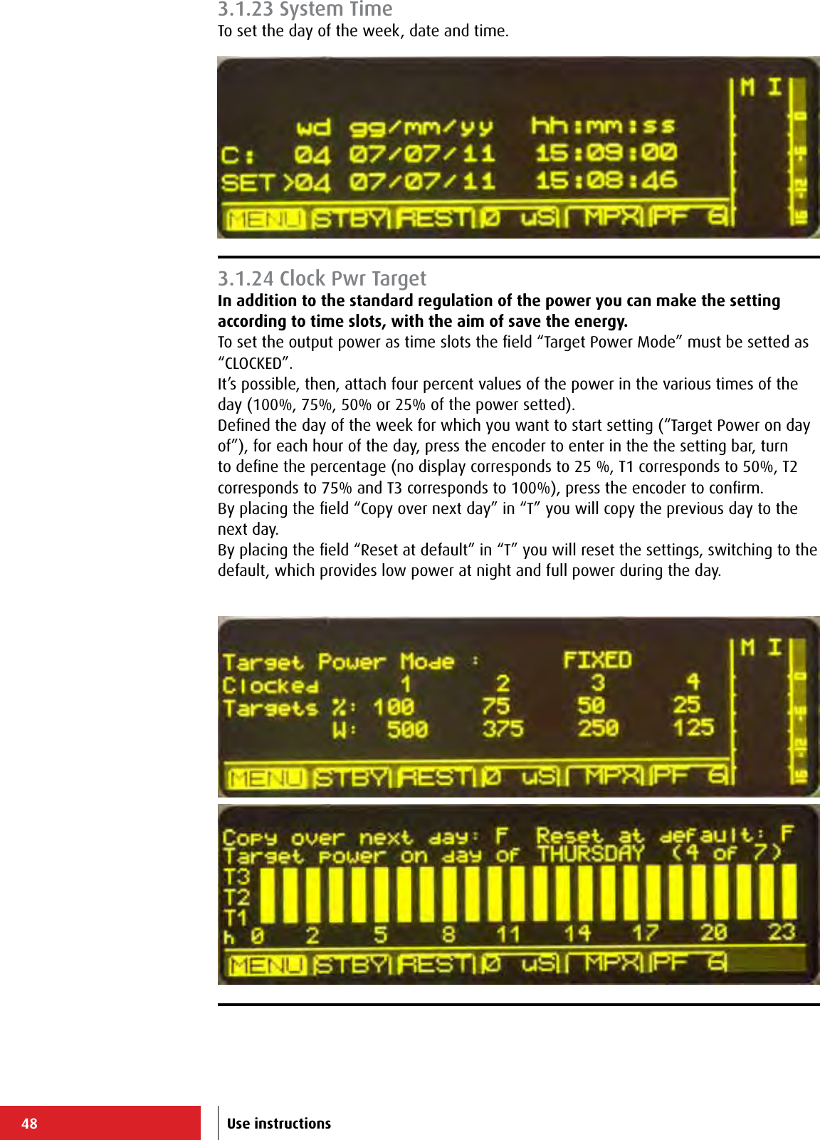
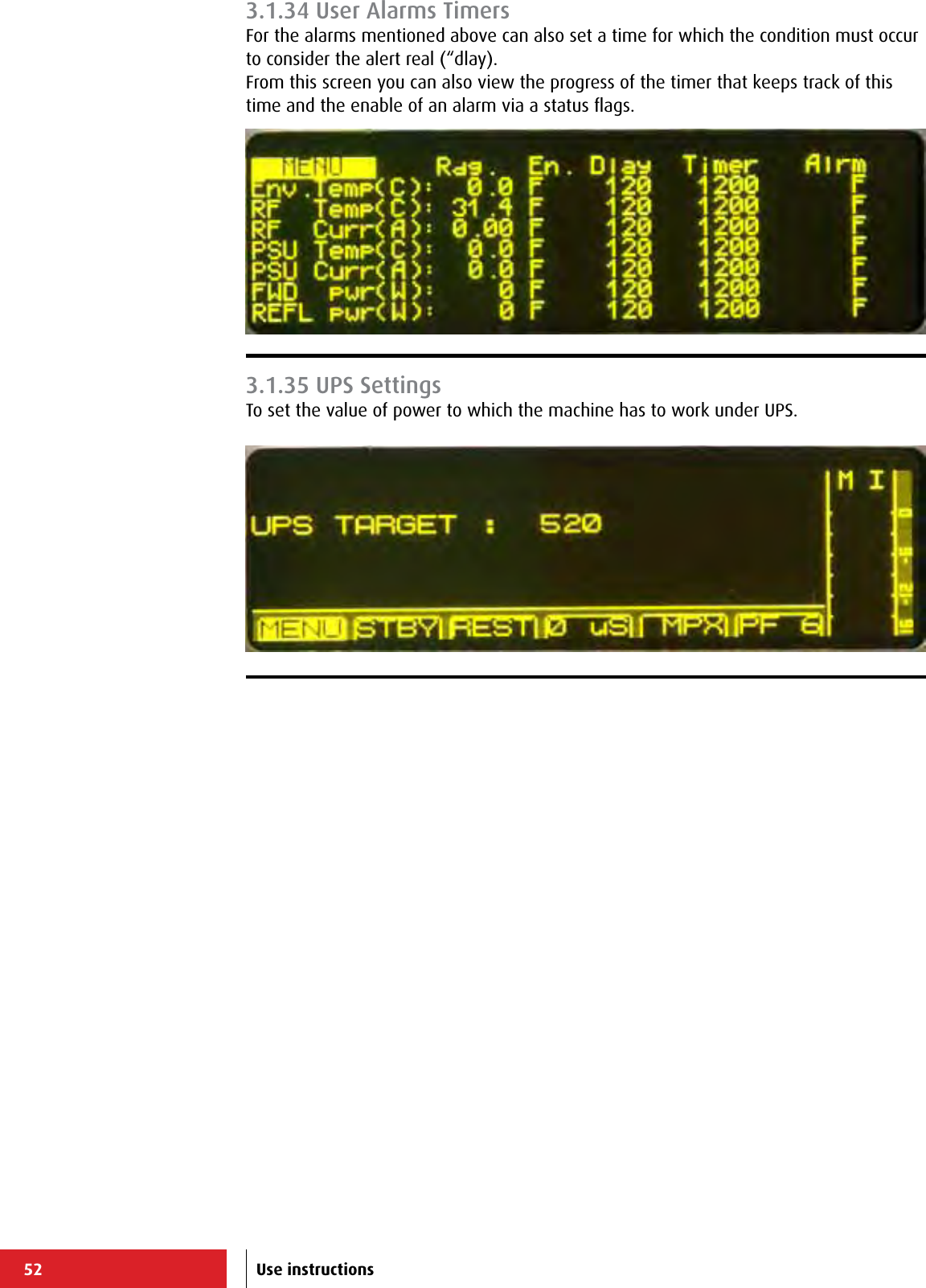
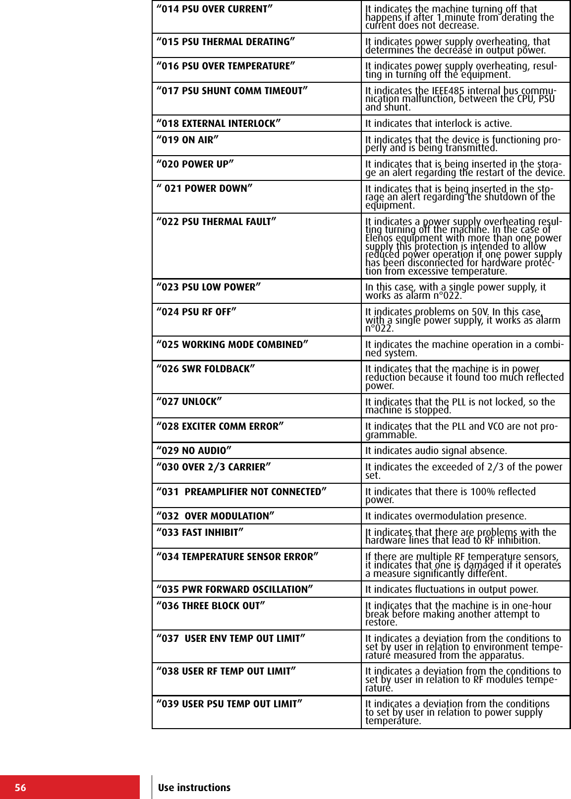
![62+-----------------------------------------------------------------------------+ | ELENOS ETG500_1P S/N.06SA0000 ELENOS <id 0000> life eXtender [menu=Q] | |-----------------------------------------------------------------------------| | ALARMS HISTORY ==> ([-] prev.pag. [+] next pag. [arrow up/down] next/prev.)| | 107) 020 POWER UP 08/07 08:52:00 | | 106) 021 POWER DOWN 08/07 08:52:00 | | 105) 020 POWER UP 08/07 08:52:00 | | 104) 021 POWER DOWN 08/07 08:52:00 | | 103) 020 POWER UP 08/07 08:52:00 | | 102) 021 POWER DOWN 08/07 08:52:00 | | 101) 004 STOP 08/07 08:52:00 | | 100) 030 OVER 2/3 CARRIER 08/07 08:52:00 | | 99) 019 ON AIR 08/07 08:52:00 | | 98) 020 POWER UP 08/07 08:52:00 | | 97) 021 POWER DOWN 08/07 08:52:00 | | 96) 004 STOP 08/07 08:52:00 | | 95) 030 OVER 2/3 CARRIER 08/07 08:52:00 | | 94) 019 ON AIR 08/07 08:52:00 | | 93) 020 POWER UP 08/07 08:52:00 | | 92) 021 POWER DOWN 08/07 08:52:00 | | 91) 004 STOP 08/07 08:52:00 | | 90) 019 ON AIR 08/07 08:52:00 | | 89) 004 STOP 08/07 08:52:00 >> | +-----------------------------------------------------------------------------+ +-----------------------------------------------------------------------------+ | ELENOS ETG500_1P S/N.06SA0000 ELENOS <id 0000> life eXtender [menu=Q] | |-----------------------------------------------------------------------------| | Status : 004 STOP 08:52 08/07 | Reset alarms :F | |-----------------------------------------------------------------------------| | Forward (W): 0 [ 500] Frequency (MHz): 98.00 RF : STBY | | Reected (W): 0 LOCK ---- ---- ---- VDS (V): 0.0 | | Eff. (%): 0.0 Prof.#: 1 ---- ---- ---- STER IDS (A): 0.00 | |-----------------------------------------------------------------------------| | ACCESS MENU (level 1) ====> 08:52:00 Fr 08/07/2011 | |-----------------------------------------------------------------------------| | K = Password | | R = Password reset +-----------------------------| | P = Password settings | E L E N O S Srl | | Q = Exit | Via G.Amendola, 9 | | | 44028 Poggio Renatico (FE) | | | ITALY | | | Tel.+39 0532 829965 | | | Fax.+39 0532 829177 | | | www.elenos.com | | +-----------------------------| | Ver. 2.14 /1.07 (c)2011 Elenos| | | +-----------------------------------------------------------------------------+ +-----------------------------------------------------------------------------+ | ELENOS ETG500_1P S/N.06SA0000 ELENOS <id 0000> life eXtender [menu=Q] | |-----------------------------------------------------------------------------| | Status : 004 STOP 08:52 08/07 | Reset alarms :F | |-----------------------------------------------------------------------------| | Forward (W): 0 [ 500] Frequency (MHz): 98.00 RF : STBY | | Reected (W): 0 LOCK ---- ---- ---- VDS (V): 0.0 | | Eff. (%): 0.0 Prof.#: 1 ---- ---- ---- STER IDS (A): 0.00 | |-----------------------------------------------------------------------------| | PASSWORD ===> | |-----------------------------------------------------------------------------| | | | Password : | | | | | | | | | | | | | | | | | | | | | +-----------------------------------------------------------------------------+ Main Menù Events History (H)Main Menù Password (K)Main Menù Password (K)Password (K)Use instructions](https://usermanual.wiki/305-BROADCAST/ETG150IS.User-Manual-2/User-Guide-2906741-Page-29.png)
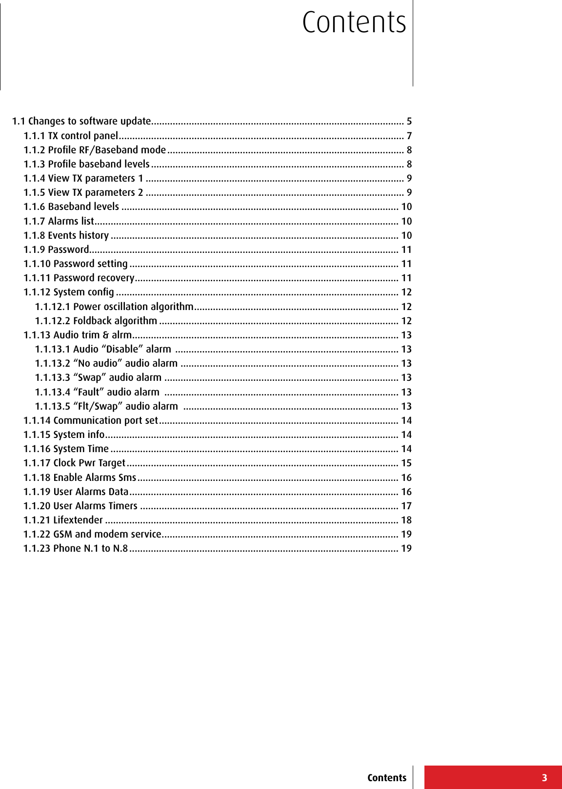
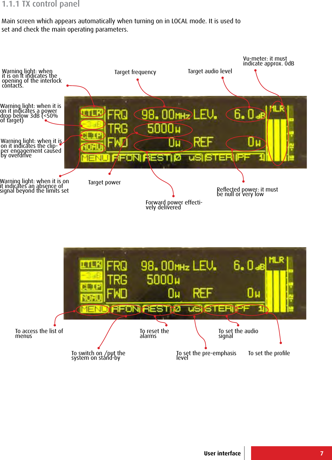
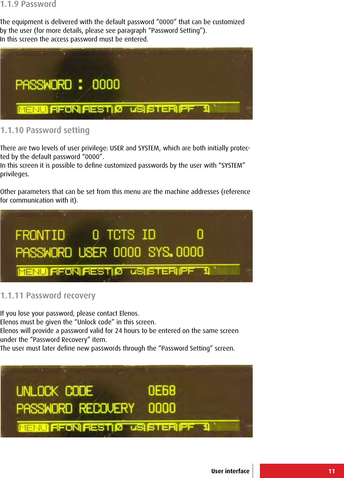
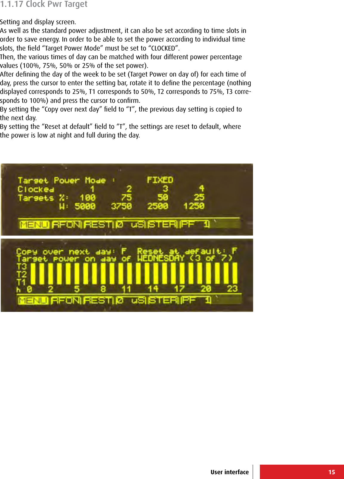
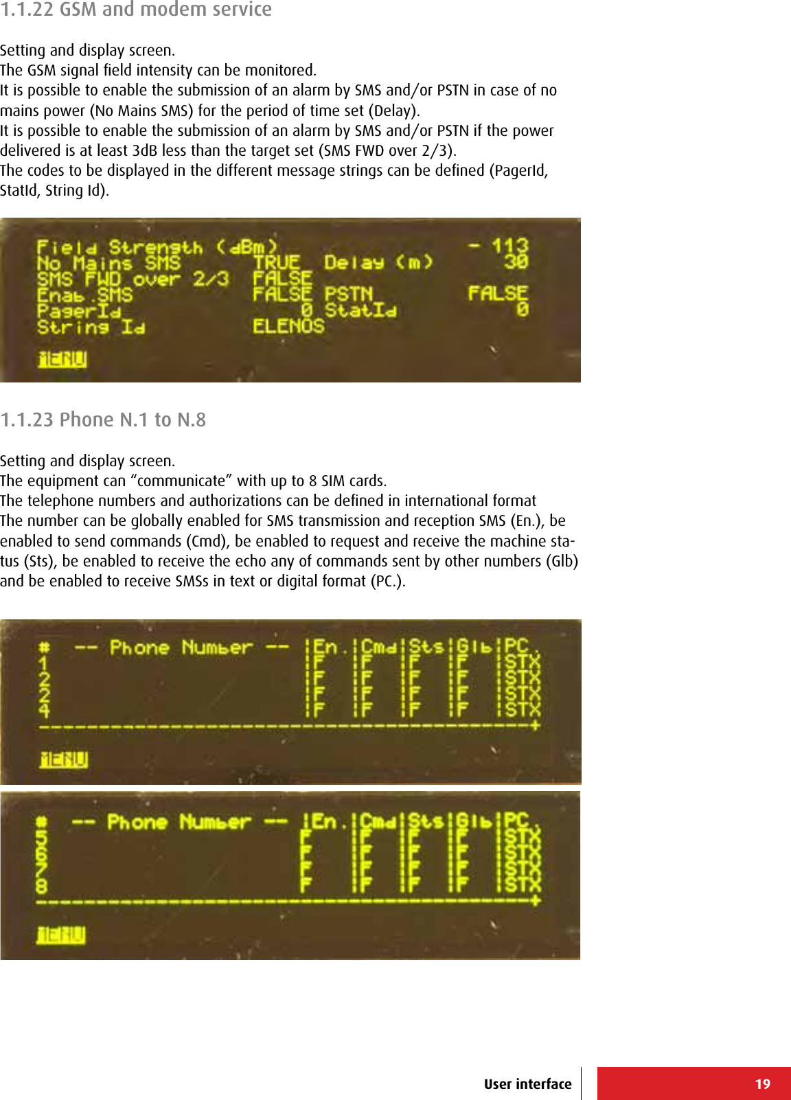
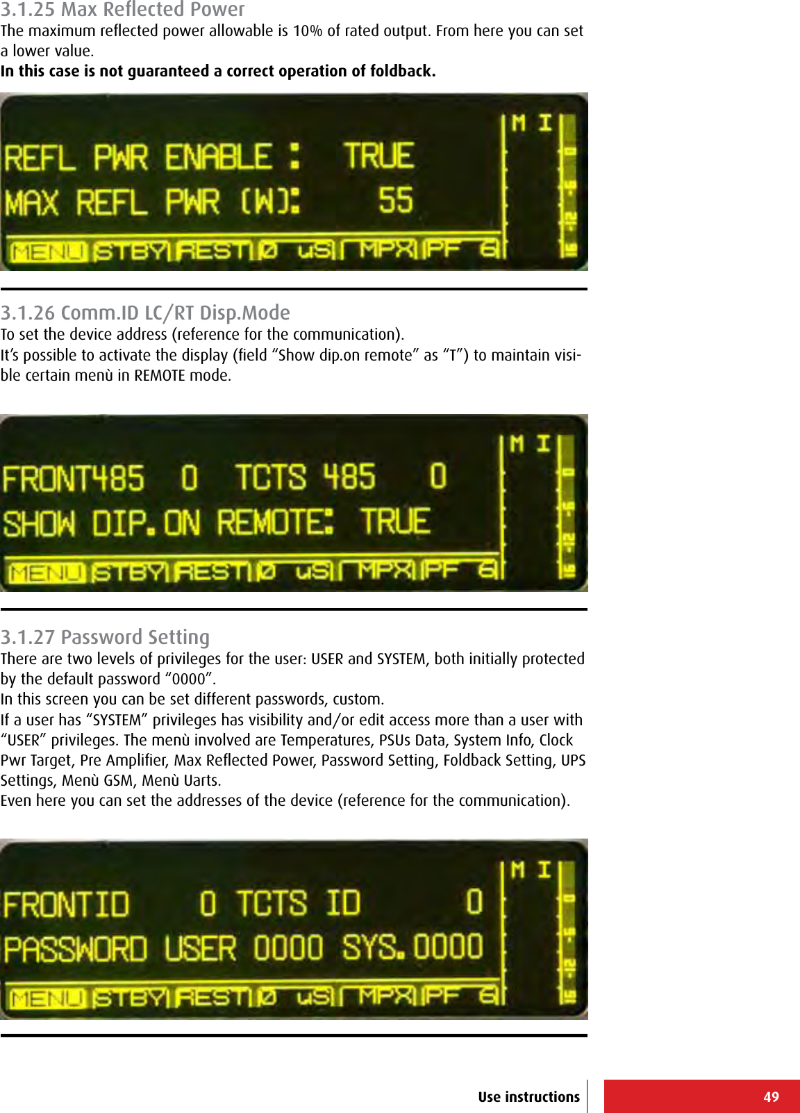
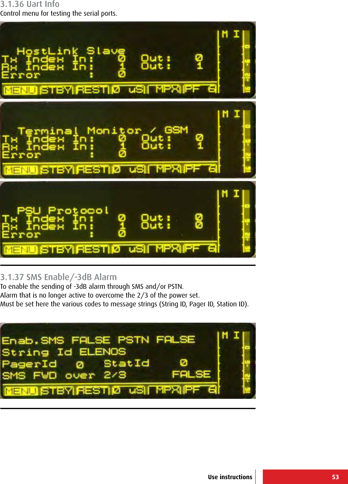
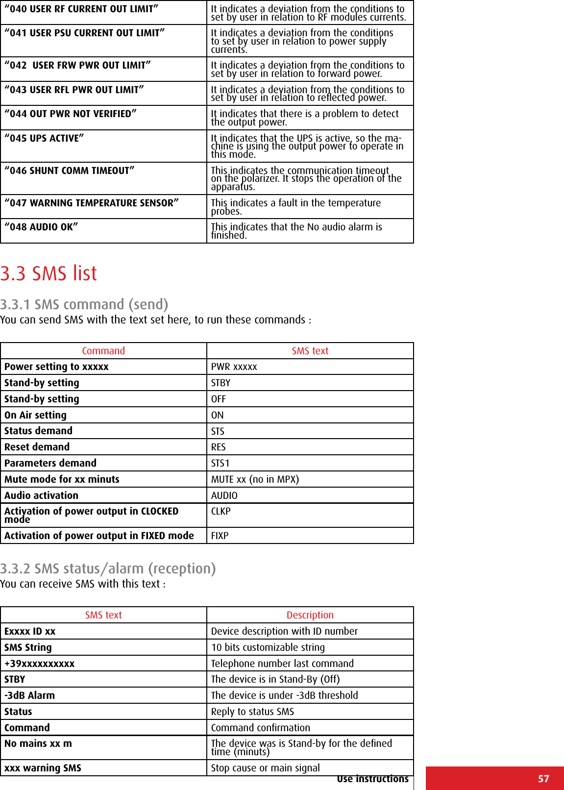
![63+-----------------------------------------------------------------------------+ | ELENOS ETG500_1P S/N.06SA0000 ELENOS <id 0000> life eXtender [menu=Q] | |-----------------------------------------------------------------------------| | Status : 004 STOP 08:52 08/07 | Reset alarms :F | |-----------------------------------------------------------------------------| | Forward (W): 0 [ 500] Frequency (MHz): 98.00 RF : STBY | | Reected (W): 0 LOCK ---- ---- ---- VDS (V): 0.0 | | Eff. (%): 0.0 Prof.#: 1 ---- ---- ---- STER IDS (A): 0.00 | |-----------------------------------------------------------------------------| | PASSWORD RESET ===> | |-----------------------------------------------------------------------------| | | | Unlock Code : 0923 | | Password Recovery : 0000 | | | | | | | | | | | | | | | | | | | +-----------------------------------------------------------------------------+ +-----------------------------------------------------------------------------+ | ELENOS ETG500_1P S/N.06SA0000 ELENOS <id 0000> life eXtender [menu=Q] | |-----------------------------------------------------------------------------| | Status : 004 STOP 08:52 08/07 | Reset alarms :F | |-----------------------------------------------------------------------------| | Forward (W): 0 [ 500] Frequency (MHz): 98.00 RF : STBY | | Reected (W): 0 LOCK ---- ---- ---- VDS (V): 0.0 | | Eff. (%): 0.0 Prof.#: 1 ---- ---- ---- STER IDS (A): 0.00 | |-----------------------------------------------------------------------------| | PASSWORD SETTINGS ===> | |-----------------------------------------------------------------------------| | | | | | User password (n.): 0000 | | System password (n.): 0000 | | | | | | | | | | | | | | | | | +-----------------------------------------------------------------------------+ +-----------------------------------------------------------------------------+ | ELENOS ETG500_1P S/N.06SA0000 ELENOS <id 0000> life eXtender [menu=Q] | |-----------------------------------------------------------------------------| | Status : 004 STOP 08:52 08/07 | Reset alarms :F | |-----------------------------------------------------------------------------| | Forward (W): 0 [ 500] Frequency (MHz): 98.00 RF : STBY | | Reected (W): 0 LOCK ---- ---- ---- VDS (V): 0.0 | | Eff. (%): 0.0 Prof.#: 1 ---- ---- ---- STER IDS (A): 0.00 | |-----------------------------------------------------------------------------| | SYSTEM MENU (level 2) ====> 08:52:00 Fr 08/07/2011 | |-----------------------------------------------------------------------------| | X = System settings | | U = Comm. settings +-----------------------------| | J = Audio trim & alrm | E L E N O S Srl | | C = Clock power set | Via G.Amendola, 9 | | P = SMS Phone set. | 44028 Poggio Renatico (FE) | | | ITALY | | F = User Warning | Tel.+39 0532 829965 | | V = En. 0-31 Alrm SMS | Fax.+39 0532 829177 | | B = En.32-63 Alrm SMS | www.elenos.com | | L = Life eXtender +-----------------------------| | Ver. 2.14 /1.07 (c)2011 Elenos| | Q = Exit | +-----------------------------------------------------------------------------+ Main Menù Password (K)Password reset (R)Main Menù Password (K)Password settings (P)Main Menù System (Y)Use instructions](https://usermanual.wiki/305-BROADCAST/ETG150IS.User-Manual-2/User-Guide-2906741-Page-30.png)
![64+-----------------------------------------------------------------------------+ | ELENOS ETG500_1P S/N.06SA0000 ELENOS <id 0000> life eXtender [menu=Q] | |-----------------------------------------------------------------------------| | Status : 004 STOP 08:52 08/07 | Reset alarms :F | |-----------------------------------------------------------------------------| | Forward (W): 0 [ 500] Frequency (MHz): 98.00 RF : STBY | | Reected (W): 0 LOCK ---- ---- ---- VDS (V): 0.0 | | Eff. (%): 0.0 Prof.#: 1 ---- ---- ---- STER IDS (A): 0.00 | |-----------------------------------------------------------------------------| | SYSTEM SETTINGS ===> | |-----------------------------------------------------------------------------| | Temperature Unit : CELSIUS | | Show Display : ALWAYS | | PLL reference (10MHz) : INT. | | Fwd Pwr Cal. (%): 100 | | SWR Foldback Enable : FALSE | | IPA Bias Treshold (V): 4.48 | | Re. Pwr Tresh. nom. (10%): TRUE | | Re. Pwr Tresh. Level (W): 55 | | PAbias (V): 5.45 | |-----------------------------------------------------------------------------| | Actual date : 08/07/2011 05 08:52:00 | | New date : 08/07/2011 05 08:52:00 UPDATE | +-----------------------------------------------------------------------------+ +-----------------------------------------------------------------------------+ | ELENOS ETG500_1P S/N.06SA0000 ELENOS <id 0000> life eXtender [menu=Q] | |-----------------------------------------------------------------------------| | Status : 004 STOP 08:52 08/07 | Reset alarms :F | |-----------------------------------------------------------------------------| | Forward (W): 0 [ 500] Frequency (MHz): 98.00 RF : STBY | | Reected (W): 0 LOCK ---- ---- ---- VDS (V): 0.0 | | Eff. (%): 0.0 Prof.#: 1 ---- ---- ---- STER IDS (A): 0.00 | |-----------------------------------------------------------------------------| | COMM. SETTINGS ===> | |-----------------------------------------------------------------------------| | Front 485 Id (n.): 0 Front 485 Speed : 9600| | TcTs 485 Id (n.): 0 | | | | Station Id : 0 | | Pager Id : 0 | | | | | | | | | | | | | | | +-----------------------------------------------------------------------------+ +-----------------------------------------------------------------------------+ | ELENOS ETG500_1P S/N.06SA0000 ELENOS <id 0000> life eXtender [menu=Q] | |-----------------------------------------------------------------------------| | Status : 004 STOP 08:52 08/07 | Reset alarms :F | |-----------------------------------------------------------------------------| | Forward (W): 0 [ 500] Frequency (MHz): 98.00 RF : STBY | | Reected (W): 0 LOCK ---- ---- ---- VDS (V): 0.0 | | Eff. (%): 0.0 Prof.#: 1 ---- ---- ---- STER IDS (A): 0.00 | |-----------------------------------------------------------------------------| | | | | | | | Pilot level : 10.00 | | Pilot phase : 0.0 | | Limiter(Clipper): 5.00 V | |-----------------------------------------------------------------------------| | | | | | | | | |-----------------------------------------------------------------------------| | No audio level (dB): -50.0 Time (s): 600 | | Over mod. level (dB): 7.1 Time (s): 600 | +-----------------------------------------------------------------------------+ Main Menù System (Y)System settings (X)Main Menù System (Y)Comm. settings (U)Main Menù System (Y)Audio trim & alrm (J)Use instructions](https://usermanual.wiki/305-BROADCAST/ETG150IS.User-Manual-2/User-Guide-2906741-Page-31.png)
![65+-----------------------------------------------------------------------------+ | ELENOS ETG500_1P S/N.06SA0000 ELENOS <id 0000> life eXtender [menu=Q] | |-----------------------------------------------------------------------------| | Status : 004 STOP 08:52 08/07 | Reset alarms :F | |-----------------------------------------------------------------------------| | CLOCK POWER SET ===> | |-----------------------------------------------------------------------------| | Target power mode xed for all the 24 hours: TRUE | | Fixed target power (W): 500 | |-----------------------------------------------------------------------------| | copy over next day : FALSE | | reset all at factory default : FALSE | | | | Target power on the 24 hours of Friday (5 of 7) | |T3 # # # # # # # # # # # # # # # # # # # # # # # # | |T2 # # # # # # # # # # # # # # # # # # # # # # # # | |T1 # # # # # # # # # # # # # # # # # # # # # # # # | |T0 00 01 02 03 04 05 06 07 08 09 10 11 12 13 14 15 16 17 18 19 20 21 22 23 | | Hours | | Target 3: 500 = 100% of xed target power | | Target 2: 375 = 75% of xed target power | | Target 1: 250 = 50% of xed target power | | Target 0: 125 = 25% of xed target power | |-----------------------------------------------------------------------------+ +-----------------------------------------------------------------------------+ | ELENOS ETG500_1P S/N.06SA0000 ELENOS <id 0000> life eXtender [menu=Q] | |-----------------------------------------------------------------------------| | Status : 004 STOP 08:52 08/07 | Reset alarms :F | |-----------------------------------------------------------------------------| | SMS PHONE SET ===> | |-----------------------------------------------------------------------------| | Field Strength dBm: - 113 | this |status |command|global | dig. | | > |account|request|execute|echo rx| SMS | | Example : +393371234567890123 |-------+-------+-------+-------+-------| | Phone N.1: | FALSE | FALSE | FALSE | FALSE | T_SMS | | Phone N.2: | FALSE | FALSE | FALSE | FALSE | T_SMS | | Phone N.3: | FALSE | FALSE | FALSE | FALSE | T_SMS | | Phone N.4: | FALSE | FALSE | FALSE | FALSE | T_SMS | | Phone N.5: | FALSE | FALSE | FALSE | FALSE | T_SMS | | Phone N.6: | FALSE | FALSE | FALSE | FALSE | T_SMS | | Phone N.7: | FALSE | FALSE | FALSE | FALSE | T_SMS | | Phone N.8: | FALSE | FALSE | FALSE | FALSE | T_SMS | |-------------------------------------+---------------------------------------| | Id string: ELENOS | Enable SMS : FALSE PSTN : FALSE | | Ok Bad | Mains alarm Enable : FALSE | | Sms sended 0 0 | Mains alarm delay (m): 30 | | Sms received 0 0 | FWD over 2/3 TARGET (-1,76DB): FALSE | +-----------------------------------------------------------------------------+ Main Menù System (Y)Clock power set (C)Main Menù System (Y)SMS phone set. (P)+-----------------------------------------------------------------------------+ | ELENOS ETG500_1P S/N.06SA0000 ELENOS <id 0000> life eXtender [menu=Q] | |-----------------------------------------------------------------------------| | Status : 004 STOP 08:52 08/07 | Reset alarms :F | |-----------------------------------------------------------------------------| | Forward (W): 0 [ 500] Frequency (MHz): 98.00 RF : STBY | | Reected (W): 0 LOCK ---- ---- ---- VDS (V): 0.0 | | Eff. (%): 0.0 Prof.#: 1 ---- ---- ---- STER IDS (A): 0.00 | |-----------------------------------------------------------------------------| | USER LIMIT WARNING SETTING ====> | |-----------------------------------------------------------------------------| | Act.Value Enable Max Min Type Delay Timer Alarm | | | |RF Temp (C): 30.9 F 90.0 98.0 UPPER 120 1200 F | |PSU Temp (C): 0.0 F 90.0 98.0 UPPER 120 1200 F | |PSU Current (A): 0.0 F 50.0 45.0 UPPER 120 1200 F | |RF Current (A): 0.00 F 1.20 1.00 UPPER 120 1200 F | |Forward PWR (%): 0 F 500 400 LOWER 120 1200 F | |Reected PWR (W): 0 F 100 90 UPPER 120 1200 F | |-----------------------------------------------------------------------------| | | | | | | +-----------------------------------------------------------------------------+ Main Menù System (Y)User Warning (F)Use instructions](https://usermanual.wiki/305-BROADCAST/ETG150IS.User-Manual-2/User-Guide-2906741-Page-32.png)
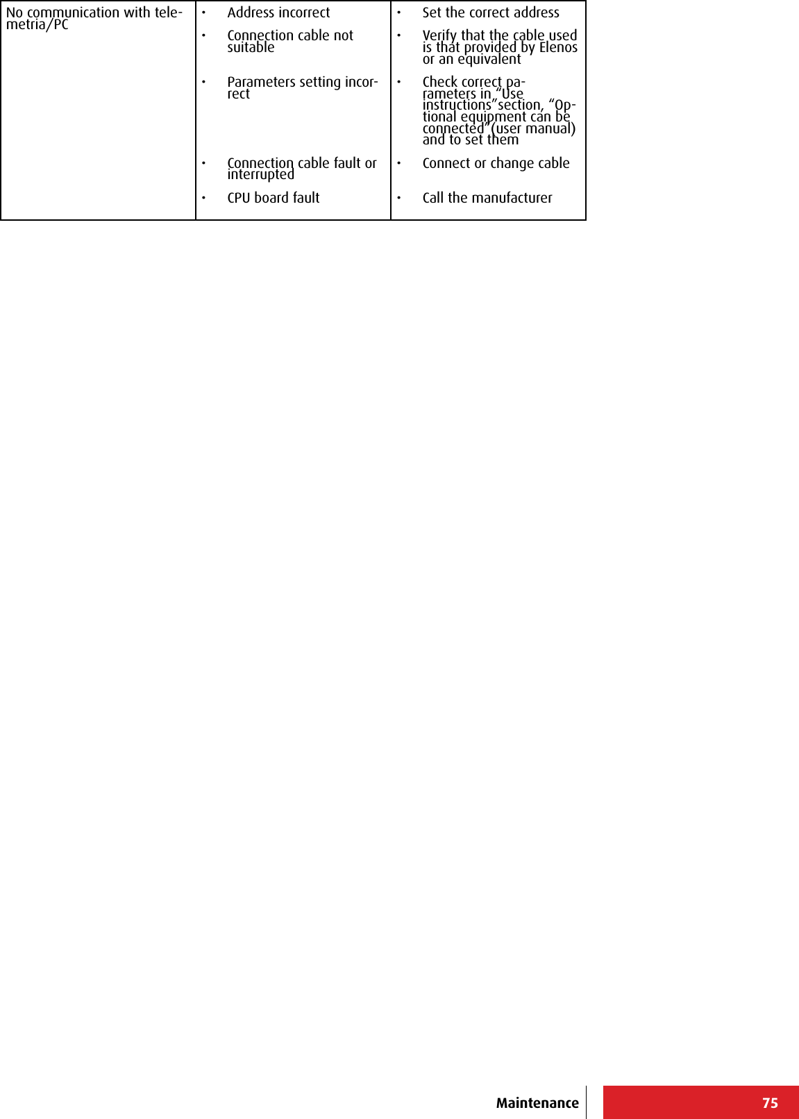
![66+-----------------------------------------------------------------------------+ | ELENOS ETG500_1P S/N.06SA0000 ELENOS <id 0000> life eXtender [menu=Q] | |-----------------------------------------------------------------------------| | Status : 004 STOP 08:52 08/07 | Reset alarms :F | |-----------------------------------------------------------------------------| |Bit Status Bit Status | | | / Enable | / Enable | | 0 F F 000 CORRECT WORKING 16 F F 016 PSU OVER TEMPERATURE | | 1 F F 001 SYSTEM RESET 17 F F 017 PSU COMM TIMEOUT | | 2 F F 002 EEPROM CHKSUM ERROR 18 F F 018 EXTERNAL INTERLOCK | | 3 F F 003 BLOCKED 19 F F 019 ON AIR | | 4 T F 004 STOP 20 F F 020 POWER UP | | 5 F T 005 -3dB CARRIER 21 F F 021 POWER DOWN | | 6 F F 006 HIGH REF PWR 22 F F 022 PSU THERMAL FAULT | | 7 F F 007 MIN 12V 23 F F 023 PSU LOW POWER | | 8 F F 008 RF AMP. FAULT 24 F F 024 PSU RF OFF | | 9 F F 009 RF AMP. FAULT DERATING 25 F F 025 WORKING MODE COMBINED | |10 F F 010 RF THERMAL DERATING 26 F F 026 SWR FOLDBACK | |11 F F 011 RF OVER TEMPERATURE 27 F F 027 UNLOCK | |12 F F 012 PSU FAULT 28 F F 028 EXCITER COMM ERROR | |13 F F 013 PSU CURRENT DERATING 29 F T 029 NO AUDIO | |14 F F 014 PSU OVER CURRENT 30 F F 030 OVER 2/3 CARRIER | |15 F F 015 PSU THERMAL DERATING 31 F F 031 PREAMPLIFIER NOT CONNEC | +-----------------------------------------------------------------------------+ +-----------------------------------------------------------------------------+ | ELENOS ETG500_1P S/N.06SA0000 ELENOS <id 0000> life eXtender [menu=Q] | |-----------------------------------------------------------------------------| | Status : 004 STOP 08:52 08/07 | Reset alarms :F | |-----------------------------------------------------------------------------| |Bit Status Bit Status | | | / Enable | / Enable | |32 F F 032 OVER MODULATION 48 F F | |33 F F 033 FAST INHIBIT 49 F F | |34 F F 034 TEMPERATURE SENSOR ERRO | |35 F F 035 PWR FORWARD OSCILATION | |36 F F 036 THREE BLOCK OUT | |37 F F 037 USER ENV TEMP OUT LIMIT | |38 F F 038 USER RF TEMP OUT LIMIT | |39 F F 039 USER PSU TEMP OUT LIMIT | |40 F F 040 USER RF CURRENT OUT LIM | |41 F F 041 USER PSU CURRENT OUT LI | |42 F F 042 USER FRW PWR OUT LIMIT | |43 F F 043 USER RFL PWR OUT LIMIT | |44 F F 044 OUT PWR NOT VERIFIED | |45 F F 045 UPS ACTIVE | |46 F F | |47 F F | +-----------------------------------------------------------------------------+ Main Menù System (Y)En. 0-31 Alrm SMS (V)Main Menù System (Y)En. 32-63 Alrm SMS (B)+-----------------------------------------------------------------------------+ | ELENOS ETG500_1P S/N.06SA0000 ELENOS <id 0000> life eXtender [menu=Q] | |-----------------------------------------------------------------------------| | Status : 004 STOP 08:52 08/07 | Reset alarms :F | |-----------------------------------------------------------------------------| | Forward (W): 0 [ 500] Frequency (MHz): 98.00 RF : STBY | | Reected (W): 0 LOCK ---- ---- ---- VDS (V): 0.0 | | Eff. (%): 0.0 Prof.#: 1 ---- ---- ---- STER IDS (A): 0.00 | |-----------------------------------------------------------------------------| | LIFE EXTENDER ACTIVATION / DEACTIVATION ===> | |-----------------------------------------------------------------------------| | SerialNumber : 06SA0000 | | Unlock Code : fe98 | | Deactivation Code : | | | | LIFE EXTENDER Status : ACTIVE | | Working Days Good Condition : 3 | | Working Days Critical Cond. : 0 | | Working Time : 0 | | | | | | | | |+-----------------------------------------------------------------------------+ Main Menù System (Y)Life eXtender (L)Use instructions](https://usermanual.wiki/305-BROADCAST/ETG150IS.User-Manual-2/User-Guide-2906741-Page-33.png)